* Corresponding Author : [email protected]
+ This Work was supported by the Power Generation & Electricity Delivery Core Technology Program of the Korea Institute of Energy Technology Evaluation and Planning (KETEP), Granted Fnancial Resource from the Ministry of Trade, Industry & Energy, Republic of Korea.
Manuscript receivred September 21, 2017/ revised January
11 ,2018 / accepted February 27, 2018 1) 창원대학교 전기공학과, 제 1 저자 2) 창원대학교 전기공학과, 제 2 저자 3) 창원대학교 전기공학과, 제 3 저자 4) 창원대학교 전기공학과, 제 4 저자 5) 창원대학교 전기공학과, 교신저자
1500 A, 400 mH급 초전도 직류 리액터용 극저온 냉각 시스템 구조 설계 및 열 해석
(Structure Design and Thermal Analysis of Cryogenic Cooling System for a 1500 A, 400 mH Class HTS DC Reactor)
권 다 어 반1)*, 레 덧 탕2), 성 해 진3), 박 민 원4), 유 인 근5)
(Quan Dao-Van, Le Tat-Thang, Sung Hae-Jin, Park Min-Won, and Yu In-Keun)
요 약 이 논문에서는 대 전류, 고온 초전도 직류 리액터를 위한 전도 냉각 시스템의 구조 설계 에 대해 논의하고자 한다. 초전도 자석, 보 빈, 전류 리드, 고정용 구조물 그리고 열 교환기가 포함된 전도 냉각 시스템 부품의 크기를 3D CAD 프로그램을 사용하여 계산하였다. 또한, 최적의 설계 변수 를 결정하고 열적-기계적 특성을 분석하기 위해서 유한 요소법 모델을 제작하였다. 리액터 자석의 운 전 전류와 인덕턴스는 각각 1,500 A 400 mH이며, 이에 따른 극저온 냉동기의 냉각 용량을 결정하기 위해 초전도 직류 리액터에서 발생하는 열 부하를 계산하였다. 또한, 대 전류가 흐르는 1 단부전도 냉각 시스템의 작동 테스트를 수행하였다. 구리 바는 40 K까지 냉각되었고 초전도 리드는 안정적으 로 작동했다. 실험 결과로써, 1 단부 영역의 총 열 부하는 190 W였다. 본 연구 결과는 상용 초전도 직류 리액터의 설계 및 제조에 있어 효과적으로 활용 될 것이다.
핵심주제어 : 고온 초전도, 고 전류 직류 리액터, 전도 냉각, 고온 초전도 자석
Abstract This paper discusses a structure design and thermal analysis of cryogenic conduction cooling system for a high current HTS DC reactor. Dimensions of the conduction cooling system parts including HTS magnets, bobbin structures, current leads, support bars, and thermal exchangers were calculated and drawn using a 3D CAD program. A finite element method model was built for determining the optimal design parameters and analyzing the thermo-mechanical characteristics. The operating current and inductance of the reactor magnet were 1,500 A, 400 mH, respectively. The thermal load of the HTS DC reactor was analyzed for determining the cooling capacity of the cryo-cooler. Hence, we carried out the operating test of conduction cooling system of the 1st stage area with high current flow. The cooper bars was cooled down to 40 K and HTS leads operated stably. As a experiment result, the total heat load of the 1st stage area is 190 W. The study results can be effectively utilized for the design and fabrication of a commercial HTS DC reactor.
Key Words : High Temperature Superconducting, High Current DC Reactor, Conduction Cooling, HTS Magnet
1. Introduction
Large electric power systems, such as high voltage direct current (HVDC) transmission systems, need a DC reactor with high inductance and high transport current. However, systems typically experience a lot of electrical losses due to the resistance of the metal winding. HTS magnet has zero electric resistance under DC current conditions and it is possible to increase the capacity of the transport current, hence, reduce the reactor’s size, weight, and electrical losses [1-4]. needs cryogenic cooling to achieve and maintain its superconducting state. There are two cooling methods; the one is pool boiling the HTS magnet in cryogen, and the other is conduction cooling by connecting the HTS magnet to a cryo-cooler directly or indirectly in a vacuum chamber. The conduction cooling system is more effective, smaller, and lighter than the pool boiling method [5-7]. An optimal design of the conduction cooling system is an important factor to operate the reactor stably and effectively.
This paper discusses a structure design of cryogenic conduction cooling system for high current HTS DC reactor. The inductance and the operating current of the HTS DC reactor were 400 mH and 1500 A, respectively.
Dimensions of conduction cooling system parts including HTS magnets, bobbin structures, current leads, support bars, and thermal exchangers were calculated and drawn using a 3D CAD program. A finite element method mol was developed for determining the optimal design parameters and analyzing the thermal characteristics. The simulation results were analyzed and are described in detail. Then, the operating test of conduction cooling system for
the 1st stage area was carried out. The cryo-coolers, cryostat, radiation shield and current lead system were assembled. Hence, the cool down and saturation temperatures in current leads system were measured and compared to simulation results. This study results can be effectively utilized for the design and fabrication of a commercial HTS DC reactor.
2. Design of a 1,500 A, 400 mH Class HTS DC Reactor
2.1 Structure Design of the HTS DC Reactor
Fig. 1 shows the structure and size of a toroid-type HTS DC reactor magnet. The D-shape HTS double package coil (DPC) was applied to the reactor magnet. The toroid-type magnet consists of 30 DPCs. The inner diameter and outer diameter of the reactor magnet are 439.24 mm and 933.81 mm, respectively. The D-shape DPCs are arranged at an angle of 120o from each other based on the central axis of the toroid-type magnet. That is, all coils constituting the toroid-type magnet are arranged at identical intervals. The wire length of one D-shape DPC is 101.8 m, and the total wire length of the toroid-type HTS DC reactor magnet is about 3,054 m. The basic structure was referred to the previous research [2], and the major dimensions of the HTS DC reactor were modified to minimize the cooling capacity of the cryo-coolers in this paper. Two layered GdBCO HTS wires were used for the reactor magnet. The critical current (Ic) was 1,200 A at a temperature of 77 K. The wire width and thickness are 12 mm and 0.61 mm. The calculated inductance of the reactor magnet was 404.59 mH. The detailed
specifications of the 1,500 A, 400 mH class toroid-type HTS DC reactor magnet are shown in Table 1.
Fig. 1 Detail Size of the D-Shape DPC and Magnet Structure
Parameters Value
Wire Type 2G HTS wire
Thickness of Wire 0.61 mm
Width of Wire 12 mm
Operating Current 1,500 A Magnet Inductance 404.59 mH Length of Wire (SPC/DPC) 50.9/101.8 m
Number of DPC 30 ea
Total Length of Wire 3,504 m Number of Turns 57 turns Width of Magnet 933.81 mm Height of Magnet 370.76 mm Table 1 Modified Specifications of HTS DC Reactor
2.2 Electromagnetic Analysis Result of HTS DC Reactor Magnet
A 1/10 numerical model of the toroid-type DPC HTS DC reactor magnet was built in the Matlab program as shown in Fig. 2. The flux density of HTS DC reactor magnet was calculated by a numerical method based on Biot-Sawart law. The highest magnetic flux density area of the D-shape coil needs to be considered for determining the critical current of HTS coil. The magnetic flux density results
were shown in Fig. 3. The maximum perpendicular and the parallel flux density were 1.57 T and 4.37 T, respectively. The values obtained by the numerical calculation were applied to all of the DPCs in order to determine the parameters of the magnet.
Fig. 2 1/10 Numerical Model of the Toroid-Type HTS DC Reactor Magnet
(a)
(b)
Fig. 3 Magnetic Flux Density in D-Shape DPC: (a) Parallel Flux Density, (b) Perpendicular Flux Density
2.3 Conduction Cooling System
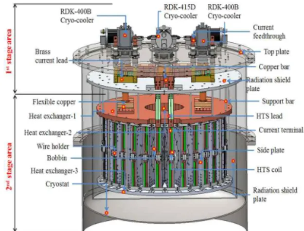
In this study, a conduction cooling system was used for cooling the toroid-type HTS DC reactor magnet. In this cooling method, the single-stage (RDK-400) and two-stage (RDK-415D) type Gifford-McMahon (GM) cryo-cooler (Sumitomo Corp.) were adopted. The conduction cooling system of HTS DC reactor mainly consists of the 1st and 2nd stage areas as shown in Fig. 4.
The 1st stage area is structured to carry currents via the DC reactor magnet in the room temperature section. A current supplied from the outside into the inside of the cryostat through two 800 A class current feedthroughs and then a current is supplied to the reactor magnet through brass current lead, copper stick, and HTS current lead. The 2nd stage area cools HTS DC reactor magnet. 30 DPCs were arranged in a toroid shape through the heat exchanger located in the lower and upper side of the DPC.
Fig. 4 Configuration of the Conduction Cooling System of HTS DC Reactor
2.3.1 Design of the 1st Stage Area
In the 1st stage area of the conduction cooling system, three cold heads of the GM cryo-coolers (single and two-stage) are
responsible for the cooling of current leads and radiation shields.
Several important factors must be determined in order to design current leads, including the choice of materials and the lead geometry (length, cross section area, cooling surface area) [8,9]. Fig. 5 shows schematic layout of a conduction current lead with a length of L, a cross sectional area of A, and a carrying current of I, and represent the temperature of the warm and cold ends, respectively. Assume the lead has a uniform temperature distribution on the cross section, such that and are the thermal conductivity and the electric resistivity of the material. The minimum heat load can be written as (1), and the optimal length of the current lead can be determined by (2):
Fig. 5 Schematic Layout of Conduction Current Lead
(1)
(2)For pure metals, and are inversely related, according to the Wiedemann-Franz law:
(3)
Here, × , Hence, the equation (1) and (2) can be rewritten as:
(4)
(5)
The current lead system, including current feedthroughs, brass loop current leads, copper bars and HTS leads was designed using a 3D CAD program using calculation results. In the 1st stage area, four current feedthroughs were used for vacuum condition. The current flow in each current feedthrough was 750 A. To reduce the Joule heat, the HTS wires were attached to copper bars. The HTS leads were also connected to copper bars to conduct current to the HTS magnet. Thus, the optimal design of the brass current leads was performed. The minimum heat load in the current feedthroughs and the brass current leads were calculated by (1). The optimal length and thickness of the brass current leads were also determined by (5).
Fig. 6 shows the configuration the current lead system of the 1st stage area in the 1,500 A, 400 mH class HTS DC reactor.
Fig. 6 Configuration of the Current Lead System of the 1st Stage Area in HTS DC
2.3.2 Design of the 2nd Stage Area
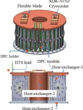
The 2nd stage cold heads of two GM cryo-coolers (RDK-415D) are responsible for cooling of the toroid-type magnet. Fig. 7 shows the detail configuration of the 2nd stage area. The coils are cooled by aluminum conducting bars assembled on the top and bottom of the coils. In addition, between each coil and the cryo-coolers, the heat exchangers made of oxygen free copper (OFCu), aluminum and a flexible copper blade are installed in order to support and cool the 30 double pancake coils simultaneously.
Fig. 7 Detail Configuration of the 2nd Stage Area
The bobbin structures and the shape of DPC module are described in detail in Fig. 8. The DPC module for an HTS DC reactor magnet is composed of two D-shape coils, two bobbins, two side plates and joint parts (joint plate, wire holder).
Fig. 8 Bobbin Structures and the Shape of DPC Module
3. Thermal Analysis and Optimal Design of the Conduction Cooling System
3.1 FEM Simulation
From the 3D CAD design, the thermal analysis for the 1,500 A, 400 mH HTS DC reactor was implemented. For basic heat load, the 1st stage, 2nd stage, radiation shield, and room temperatures were 40 K, 7 K, 77 K, and 300 K, respectively.
In the 1st stage area, the operating currents in each current feedthroughs were 750 A in
the analysis of Joule heating. In order to reduce the Joule heat, the HTS current leads were connected to copper bars. The total heat load of the current leads includes Joule heat and heat invasion at room temperature. Here, the heat invasion at room temperature is conduction heat from outside into the current leads.
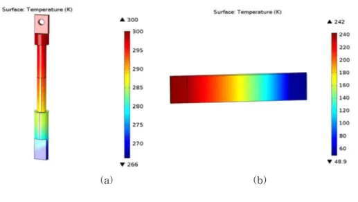
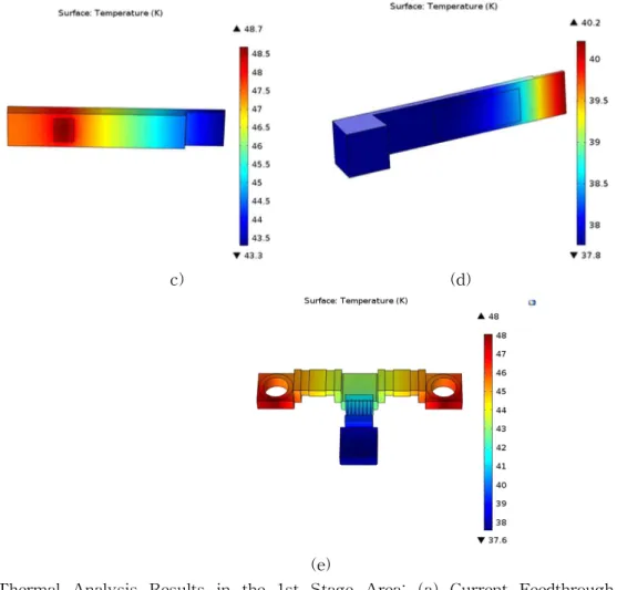
Fig. 9 shows the temperature distribution analysis result of the optimal design for the 1st stage area.
The temperatures in the copper bars connected to HTS leads and HTS wires were 38 K and 48 K, respectively. In this paper, the minimized heat load of the current lead was 76 W. The total heat load includes the Joule heat and conduction heat load. To prevent heat transfer from outside to inside of the HTS DC reactor, the conduction heat load of the current lead should be 0 W which was obtained by changing the thickness of the current lead as depicted in Fig. 10 with major parameters of the current lead.
(a) (b)
c) (d)
(e)
Fig. 9 Thermal Analysis Results in the 1st Stage Area: (a) Current Feedthrough, (b) Brass Current Lead, (c)-(d) Copper Bars, (e) Cooling Blocks
Fig. 10 Conduction Heat Load Depending on the Thickness of the Current Lead
The calculation and FEM simulation results in heat load of current leads (current feedthroughs and brass current leads) and thickness of the brass current lead were compared in Table 2.
Calculation FEM Heat Load of Current Leads 152.8 W 156.5 W Thickness of Brass Current
Lead 7.3 mm 7 mm
Table 2 Comparison of Calculation and FEM Simulation Results
Fig. 11 Temperature Distribution of the 2nd Stage Area of HTS DC
In the 2nd stage area, the HTS magnet stably operates at the temperature of under 20 K. Fig. 11 shows the temperature distribution analysis result of the 2nd stage area. The temperature in cold head of two-stage cryo-cooler (RDK-415D) is 7.4 K. In the D-shape coil, the temperature is 15 K.
3.2 Conduction Cooling System Design
In order to analyze the thermal characteristics of the HTS DC reactor, the basic heat load of the system was considered.
Basic heat load can be divided into conduction heat and radiation heat. Conduction heat is transferred by the current lead and steel use stainless (SUS) support bars and cooler port.
Multi-Layer Insulation (MLI) reduces the radiation heat transferred from outside to inside of the HTS DC reactor. The MLI was wrapped at the surface of the radiation shield.
The thermal heat load of the HTS DC reactor in the 1st stage and 2nd stage is shown in detail in Table 3 and Table 4.
Table 3 Heat Load of the 1st Stage Area 1st Stage Heat Load (W)
Current Feedthroughs (4 ea) 48.84 W Brass Current Leads (4 ea) 104 W
Radiation Shield 12.4 W
Support Bars 6 W
Total Heat Load 171.24 W
Table 4 Heat Load of the 2nd Stage Area 2nd Stage Heat Load (W)
Conduction Heat Load from Support 1.2 W Conduction Heat Load from HTS Lead 0.016 W
Magnet Joint 6 W
Current Terminals 0.018 W
Total Heat Load 7.234 W
4. Experiment results and discussion
In this paper, the operating tests of the conduction cooling system and current leads in the 1st stage area were carried out as shown in Fig. 12. The cryo-coolers, cryostat, radiation shield and current lead system were assembled. Two copper blocks were attached to the input and output points of HTS leads to hold HTS wires for testing. To monitor the change of temperature, eight silicon diode sensors (DT-760) were attached to the cooling blocks, current leads, HTS leads and radiation shield. The cool down and saturation temperatures in the current leads system were measured and compared to the simulation results.
Fig. 12 Conduction Cooling Test System for the Current Lead System
4.1 Cooling down of Current Leads by Conduction Cooling System
Fig. 13 shows the cool down curve of the conduction cooling system without current flow.
Fig. 13 Cooling down Curve without Current flow in the current leads
It took about 20 hours to cool down the saturation temperature. The copper bars were cooled down to below 40 K and the HTS wires and HTS leads can be operated.
4.2 High Current Operating Test
Fig. 14 shows the temperature variations for at each position in the 1st stage area with operating current of 1500 A.
Fig. 14 Temperature Curve with High Current Flow in the Current Leads
The saturation temperature with high current flow of the current lead system was compared to the FEM simulation results as shown in Fig. 15.
(a)
(b)
Fig. 15 Saturation Temperature with High Current Flow of the Current Lead System: a) FEM Simulation Results, b) Experiment Results The temperature of cooling block 4 and
input and output points of HTS leads in the experiment results was higher than the FEM simulation results because of conduction heating in two copper blocks which to the input and output points of HTS leads. The total heat load of the 1st stage area was about 190 W.
5. Conclusions
The authors designed a conduction cooling system for a toroid-type HTS DC reactor magnet and analyzed its thermal characteristics.
The operating current and inductance of the reactor magnet were 1,500 A, 400 mH, respectively. The detailed structure design of conduction cooling system in the 1st stage area and 2nd stage area were described. The optimal heat load of HTS DC reactor was calculated and analyzed by FEM simulation. The conduction cooling system including cryo-coolers, cryostat, cooling blocks, current leads was assembled to demonstrate the efficient operation of the design.
As a result of experiment test, the saturation temperature of copper bars with the operating current of 1500 A was cooled down to 40 K and HTS leads operated stably. The total heat load of the 1st stage area is 190 W. The study results can be effectively utilized for the design and fabrication of a commercial HTS DC reactor.
References
[1] Go, B. S. Kim, K. Park, M. Kim, S. H. Yu, I. K. and Lee, S., “Detailed Design of a 2,000 A, 400 mH Toroid-Type HTS DC Reactor for an HVDC System,” J.
Supercond. Novel Magn, Vol. 28, No. 2, pp.
629-632, 2015.
[2] Kim, K. Kim, S. K. Park, M. Ha, H. S.
Sohn, M. H. Kim, K. Lee, H. Yu, I. K.,
“Design and Operating Characteristic Analysis of D-Shape HTS Coil for 1500-A 400-mH Class Toroid-Type HTS DC Reactor,” IEEE Transactions on Applied Superconductivity, Vol. 26, No. 3, pp. 1-5, 2016.
[3] Schoenung, S. M. Meier, W. R. and Hassenzahl, W. V., "A Comparison of Large-Scale Toroidal and Solenoidal SMES Systems," in IEEE Transactions on Magnetics, Vol. 27, No. 2, pp. 2324-2328, 1991.
[4] Kim, K. Kim, J. G. Jung, H. Kim, S. Lee, S. Park, M. and Yu, I. K., "Design of a 400 mH 400 A Toroid-Type HTS DC Reactor Magnet," in IEEE Transactions on Applied Superconductivity, Vol. 23, No. 3, pp.
4601104-4601104, 2013.
[5] Yeom, H. K. Hong, Y. J. Park, S. J. Seo, T. B. Seong, K. C. and Kim, H. J., "Study of Cryogenic Conduction Cooling Systems for an HTS SMES," in IEEE Transactions on Applied Superconductivity, Vol. 17, No.
2, pp. 1955-1958, 2007.
[6] Kim, K. M. Kim, A. R. Park, H. Y. Kim, J.
G. Park, M. Yu, I. K. Kim, S. H. Sim, K.
Seong, K. C. and Won, Y. J., "Design and Mechanical Stress Analysis of a Toroidal-Type SMES Magnet," in IEEE Transactions on Applied Superconductivity, Vol. 20, No. 3, pp. 1900-1903, 2010.
[7] Hong, Y. J. Yeom, H. K. Park, S. J. Kim, S. H., and Choi, Y. D. "Temperature Distribution of Cryogenic Conduction Cooling System for a HTS SMES," in
IEEE Transactions on Applied Superconductivity, Vol. 18, No. 2, pp.
745-749, 2008.
[8] Hull, Y J. R., “High Temperature Superconducting Current leads for Cryogenic Apparatus,” Energy Conversion Engineering Conference, IECEC-89., Proceedings of the 24th Intersociety, (Washington, DC), Vol. 1, pp. 459-464, 1989.
[9] Chang, H. M. Kim, M. J. “Optimization of Conduction-Cooled Current leads with Unsteady Operating Ccurrent,” Cryogenics, Vol. 49, pp. 210, 2009.
권다어반 (Quan Dao-Van)
∙학생회원
∙2015년: Hanoi University of Science and Technology 전기 공학과 학사
∙2017년: 창원대학교 전기공학과 석사
∙2017년 9월 - 현재 창원대학교 전기공학과 박사과정
∙관심분야 : 전력전자, 초전도 응용
레덧탕 (Le Tat-Thang)
∙학생회원
∙2015년: Hanoi University of Science and Technology 전기 공학과 학사
∙2017년: 창원대학교 전기공학과 석사
∙2017년 9월 - 현재 창원대학교 전기공학과 석박과정
∙관심분야 : 전력전자, 신재생 에너지, 초전도 응용
성 해 진 (Sung Hae-Jin)
∙학생회원
∙2012년: 창원대학교 전기공학과 학사
∙2016년: 창원대학교 전기공학과 석사
∙2018년: 창원대학교 전기공학과 박사
∙관심분야 : 풍력 발전, 초전도 발전기
박 민 원 (Park Min-Won)
∙정회원
∙창원대학교 전기공학과 학사
∙일본오사카대학교 전기공학과 석사
∙일본오사카대학교 전기공학과 박사
∙현재: 창원대학교 전기공학과 교수
∙관심분야 : 신재생 전력변화 시스템, 전력전자 시스 템, RTDS/RSCAD
유 인 근 (Yu In-Keun)
∙비회원
∙동국대학교 전기공학과 학사
∙한양대학교 전기공학과 석사
∙한양대학교 전기공학과 박사
∙현재: 창원대학교 전기공학과 교수
∙관심분야 : ESS, 제어 시스템, PSCAD/EMTDC, RTDS/RSCAD, 신재생 에너지