Quality Assurance of Volumetric Modulated Arc Therapy for Elekta Synergy
Su Jung Shim*, Jang Bo Shim
†, Sang Hoon Lee
‡, Chul Kee Min
§, Kwang Hwan Cho
§, Dong Oh Shin
∥, Jin Ho Choi
¶, Sung Ill Park
#, Sam Ju Cho**
*Department of Radiation Oncology, College of Medicine, Eulji University, Daejeon,
†
Department of Radiation Oncology, College of Medicine, Korea University,
‡
Department of Radiation Oncology, Cheil General Hospital & Women's Healthcare Center, Kwandong University College of Medicine, Seoul,
§
Department of Radiation Oncology, Soonchunhyang University College of Medicine, Asan,
∥
Department of Radiation Oncology, College of Medicine, Kyung Hee University, Suwon,
¶
Department of Radiation Oncology, College of Medicine, Gachon University Gil Hospital, Incheon,
#
Department of Medical Physics, Graduate School of Science, Kyonggi University, Suwon,
**Department of Radiological Science, College of Health Science, Eulji University, Seongnam, Korea For applying the quality assurance (QA) of volumetric modulated arc therapy (VMAT) introduced in Eulji Hospital, we classify it into three different QA steps, treatment planning QA, pretreatment delivering QA, and treatment verifying QA. These steps are based on the existing intensity modulated radiation therapy (IMRT) QA that is currently used in our hospital. In each QA step, the evaluated items that are from QA program are configured and documented. In this study, QA program is not only applied to actual patient treatment, but also evaluated to establish a reference of clinical acceptance in pretreatment delivering QA. As a result, the confidence limits (CLs) in the measurements for the high-dose and low-dose regions are similar to the conventional IMRT level, and the clinical acceptance references in our hospital are determined to be 3 to 5% for the high-dose and the low-dose regions, respectively. Due to the characteristics of VMAT, evaluation of the intensity map was carried out using an ArcCheck device that was able to measure the intensity map in all directions, 360
o. With a couple of dosimetric devices, the gamma index was evaluated and analyzed. The results were similar to the result of individual intensity maps in IMRT. Mapcheck, which is a 2-dimensional (2D) array device, was used to display the isodose distributions and gave very excellent local CL results. Thus, in our hospital, the acceptance references used in practical clinical application for the intensity maps of 360
odirections and the coronal isodose distributions were determined to be 93% and 95%, respectively. To reduce arbitrary uncertainties and system errors, we had to evaluate the local CLs by using a phantom and to cooperate with multiple organizations to participate in this evaluation. In addition, we had to evaluate the local CLs by dividing them into different sections about the patient treatment points in practical clinics.
Key Words: Treatment verifying QA, IMRT, VMAT, Confidence limit, QA protocol
This work has supported by the BumSuk Academic Research Fund of 2009.
Submitted February, 7, 2012, Accepted March, 2, 2012
Corresponding Author: Sam Ju Cho, Department of Radiological Science, Eulji University, 212, Yanggi-dong, Sujeong-gu, Seongnam 461-713, Korea.
Tel: 031)740-7380, Fax: 02)970-8893 E-mail: [email protected]
INTRODUCTION
Volumetric modulated arc therapy (VMAT) which recently
introduced at the Eulji Hospital is a newly developed radiation
treatment technology for implementing intensity modulated ra-
diation therapy (IMRT) more accurate and much faster. VMAT
was designed to perform IMRT using arc therapy which based
on computed tomography (CT) and the existing linear
accelerator. The principle of VMAT is to provide the max-
imum dose to target tumors and to apply the minimum dose to
normal organs by adjusting the dose rate, the multi-leaf colli-
mator (MLC), and the gantry speed while gantry rotation.
1,2)Thus, it is possible to reduce unnecessary leakage of radiation
and treatment time compared to that of the conventional
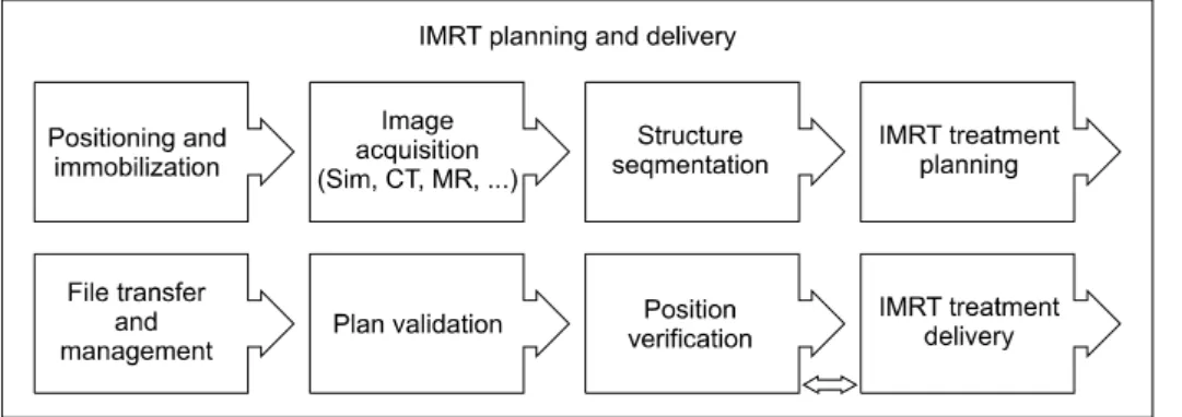
Fig. 1. The diagram shows the
overall process of IMRT planning and delivery at Eulji Hospital.IMRT. With these several advantages, VMAT increases the ef- fectiveness of radiation treatment and decreases unnecessary doses due to its low exposure dose.
3)As VMAT is complicate and advanced method, however, a proper quality assurance (QA) program is necessary to suc- cessfully perform its clinical applications. The objective of QA in radiation therapy is to address uncertainties and systematic errors in the entire process of radiation therapy in order to maximize the effect of therapy by minimizing such factors.
4)In practice, some cases that emphasized on the necessity of a proper quality assurance program for IMRT were reported at the Radiological Physics Center (RPC) 2008, USA.
5)According to that report on an investigation of 250 head phan- tom cases performed as an IMRT assurance process, 71 cases (28%) did not satisfy the 7% accuracy level at low-dose re- gion or at a 4 mm distance to agreement (DTA) condition at high-dose region. Meanwhile, the AAPM (American Association of Physicist in Medicine) Task Group 119 report on the com- missioning and quality assurance of IMRT indicated serious cases regarding the improper commissioning of the IMRT treatment plan and delivery system in corresponding organi- zations.
6)Therefore, introduction of the concept of confidence limit (CL) is required for QA of radiotherapy.
7)The CL can be determined as the sum of the average (systematic differ- ence) between the estimated and measured values, as well as the product (random difference) of the standard deviation and some factor.
8)In the equation which presented by Palta and Mackie, the CL was defined by the sum of the absolute value of the average differences and the product of the factor of 1.96 and standard deviation, [CL = | mean deviation | +1.96 SD], and shown that a measurement point of 95% satisfies the CL.
9)The configuration of CL is to be determined during
commissioning to allow errors in the measurement process to be analyzed.
10)As IMRT has long been used, the CL value has been well established by all clinics and foreign organizations around the world.
11-13)The accomplishment of confidence limit is begin- ning of the QA in VMAT. Our hospital still needs to con- figure QA program that ensures proper delivery and de- termines CL that means our local CL value before applying VMAT to actual patients through introducing the Elekta Synergy
Ⓡ(Elekta Group, Crawley, UK). Thus, in this work, the quality assurance items are determined for VMAT treat- ments which based on the related reference and conventional quality assurance items because the present VMAT is consid- ered to be an advanced treatment method that improves IMRT.
In addition, the local CL value in our hospital is calculated by the point doses for actual clinic patients, treatment maps, and isodose measurements. The values of CL are compared to the value of conventional IMRT CL so that we can verify useful- ness and validity of the CL.
MATERIALS AND METHODS
1. Quality assurance items for VMAT patients
The conventional IMRT and QA were well reported in the
2003 Guidance document on IMRT and the AAPM Task
Group 119 report.
6)Regarding the process proposed by the
2003 Guidance document on IMRT, the IMRT QA process
that is different from the conventional treatment methods in-
cludes patient setup, image acquisition, organ determination,
establishment of treatment plan, file transmission, treatment
evaluation, treatment position verification, and treatment deliv-
ery (Fig. 1). Thus, the QA items required in VMAT were se-
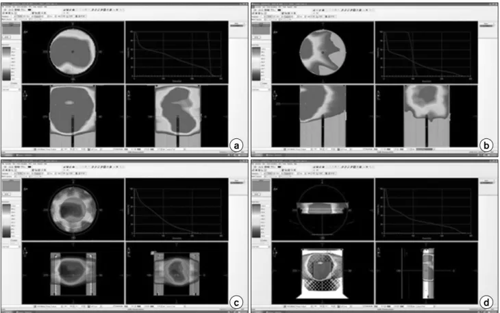
Fig. 2. The dosimetric QA of VMAT. (a) High-dose region’s point-dose QA plan with a cylindrical phantom, (b) low-dose region’s
point-dose QA plan with a cylindrical phantom, (c) 360-degree fluence-map QA plan with ArcCheck, and (d) isodose distribution QA plan with MapCheck.lected from among the IMRT items proposed in the literatures, and it was classified into three different QA steps, such as treatment planning QA, pretreatment delivering QA, and treat- ment verifying QA. To determine the clinical applications and acceptance references for each QA step, we applied them to 5 patients who had VMAT treatments with a total of six treat- ment plans from May to December in 2010.
2. Treatment planning step
Regarding the image acquisition process, the treatment plan- ning and delivery employed in the conventional IMRT consists of several steps such as patient position and setup, image ac- quisition, organ determination, establishment of a treatment plan, file transmission, treatment evaluation, treatment position verification, and treatment delivery. The QA in VMAT was classified into three steps. As the first step of the QA, it in- cludes patient setup, image acquisition, organ determination,
and establishment of a treatment plan. For the image acquis-
ition of VMAT performed in our hospital, the QA items of the
variables in patient setup and image acquisition were replaced
by the existing patient record because such items were the
same as the process used in the conventional conformal radia-
tion therapy. Images of the treatment point were obtained to
establish a VMAT treatment plan by simulating previous treat-
ment computed tomographies which were transmitted to CMS
Xio (Computerized Medical System, St. Louis, MO) in order
to determine normal organs and volumes. Then, the treatment
plan was established by transmitting such images to the Monte
Carlo algorithm based IMRT planning system (Monaco version
2.03). In this step, the items for establishing and verifying a
treatment plan through cooperation between oncologists and
medical physicists were determined. In IMRT, the setup un-
certainty is determined before establishing a treatment plan for
implementing a reverse treatment plan. The final treatment
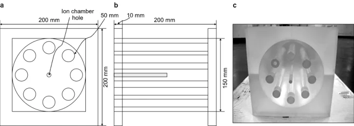
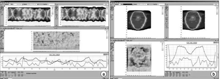
Fig. 3. The dedicated acrylic Phantom of VMAT. (a) Front view diagram of the VMAT verification phantom, (b) side view diagram,
and (c) photographic image. The 8 cylinders surrounding the inside cylinder were designed for measuring low dose region.plan is determined based on the early constraint, and it is also that a revision process for hot and cold spots must be consid- ered before the determination of the final treatment plan since several unpredictable changes are occurred in dose gradients due to the characteristics of dose distributions. Therefore, after the treatment evaluation items, such as beam pattern, isodose distribution, and dose volume histogram (DVH) in cross-sec- tion images are verified, the final treatment plan is selected based on the previous prescription. There is a verification process for intensity maps and isodose distributions before ap- plying patient treatments in IMRT. The treatment delivery QA performed for VMAT was the same as that for IMRT. The phantom treatment plans for verifying the point dose measure- ment, intensity map verification, and isodose distribution treat- ment plans were prepared (Fig. 2). The calculation algorithm used in the phantom treatment plan for the VMAT treatment delivery QA was the Monte Carlo algorithm, which had unique factors, such as a calculation of the volume grid spac- ing and Monte Carlo variance. These were recommended by the manufacturer as 0.3 cm and 5%, respectively. In IMRT, the point dose measurement is evaluated at the high-dose re- gion in the close to described dose of tumors and the low-dose region where around 10∼30% region in the pre- scribed dose. In the VMAT QA of our hospital, the treatment plan was established by measuring point doses and then com- paring the treatment plan to that measurement at least twice as it did avoid large dose gradient regions and some devices col-
lision which was the result of the phantom treatment plan. The verification of dose distributions was carried out using the MapCheck (Sun Nuclear, USA) with respect to the coronal ax- is of the center point, and a simulation was implemented to determine the proper treatment plan. Because it is impossible to obtain fluence maps for each individual radiation field due to the characteristics of VMAT, the ArcCheck (Sun Nuclear, USA) system, which is able to evaluate treatment maps for 360
o, was used.
Although treatment delivery information, which is trans- mitted through a network to produce a database for patient treatment, is used to operate the radiation treatment system, some documents are required to perform cross check of patient information during the transmission and registration processes.
Thus, items were setup to check the normal documents in the radiation treatment plan report used for the patient treatment charts.
3. Pretreatment delivery step
In the pretreatment delivery step, the items for verifying the
delivery of patient treatment information and checking pretreat-
ment delivery QA were set-up as patient treatment QA. The
patient treatment information was established in a database
server, Mosaiq (Impac software, Elekta Group, UK), and the
radiation treatment could be performed with a linear
accelerator. Then, in the treatment planning system, the treat-
ment information is transmitted from a DICOM format to the
Fig. 4. Volumatric modulated arc
therapy (VMAT) quality assurance (QA) program at Eulji Hospital.database server after completing the treatment plan. The Mosaiq system registers the files that correspond to each patient. Based on the current system installed in our hospital, the treatment information delivery items for verifying the val- idities of file transmission and registration were set-up by us- ing the treatment planning report in order to remove any errors that occurred during the transmission process. In the case of the measurement of point doses, which is the same as the ex- isting IMRT, QA in VMAT is essential. The acceptance refer- ence for the difference between the doses measured for the phantom and for the treatment plan was clinically configured based on many studies performed by researchers and research organizations in the case of IMRT. In general, for IMRT, the references are defined within 3 to 5% for the high-dose region and the low-dose region with around 10∼30% of the pre- scribed dose, whereas the acceptance reference for the point dose measurement in VMAT has still not been prepared. Thus, the acceptance reference was prepared with calculating the lo- cal CL for our hospital based on the results obtained by meas- uring actual patients. The point dose CL was determined using the equation [CL = | mean deviation | +1.96 SD]. An ex- clusive phantom was made of acryl to reduce phantom setup errors in the measurement of point doses and to improve the measurement practicality (Fig. 3). In the measurements of point doses, a 0.125 cc ion chamber (Semiflex Type 31010, PTW, Germany) was used. Also, the exclusive phantom was configured as a SAD (source to axis distance) setup condition
and a dose of 100 cGy was delivered to an area of 10×10 cm
2. Then, the reading of the electrometer was used as a dose conversion factor. In addition, the values of the point doses were obtained by applying the dose conversion factor to the values obtained for the high-dose and the low-dose regions de- termined in the treatment plan. Although the conventional IMRT treatment verifies the intensity map for a specific radia- tion field, in the case of VMAT, such an intensity map is dif- ficult to verify at a single radiation field because the treatment in VMAT is carried out by rotating directions 360
o, without any fixation, so conventional films or 2D arrays are not useful for checking the intensity map in VMAT. The ArcCheck sys- tem, which was able to measure and analyze the intensity map for all directions 360
o, was introduced for the comparison and analysis of the intensity map in VMAT.
In addition, the evaluation of the isodose distributions was performed by introducing the MapCheck system at a coronal plane. In order to compare and evaluate the results that ob- tained in these systems, a gamma index evaluation method was used. In the case of IMRT, the acceptance reference was determined to satisfy with a limit of 95% by configuring the references of 3 mm and 3% in the gamma index evaluation.
However, the acceptance reference for VMAT and for the measurement of point doses has not been established.
Therefore, the acceptance reference was determined by evaluat-
ing the local CL employed in our hospital based on a retro-
spective evaluation of the measured limits for the patients in
Table 1. Characteristics of patients and VMAT treatment plan.
No Sex/Age Tx.* site Dose (cGy)/Fr.** #*** of Fr. # of segment Tx. Area (cm2) Total MU****/Fr.
1 2 3 4 5 6
F/21 M/26 M/71 M/44 M/71 M/58
Skull base Brain Prostate Lung Prostate Nasal cavity
400 200 400 500 200 200
10 30 20 10 15 10
139 89 212 162 167 153
18.3 104.95 224.03 26 64.06 47.27
661.10 439.90 880.30 965.80 702.10 488.16
*Treatment, **Fraction, ***Number, ****Monitor unit.
Table 2. Evaluation of the CLs for the high-dose region’s point dose and the low-dose region’s point dose, and the treatment map and the isodose distribution.
Pt.* 1 2 3 4 5 6 Mean SD** CL***
High dose (%) Low dose (%) Treatment map (%) Isodose distribution (%)
−0.56 1.74 1.6
0
−2.15
−2.79 3.2 0.5
−2.38
−0.48 5.9 3.1
0.37 4.66 1.9 0.6
−1.84
−1.48 3 2.9
−2.52
−0.84 5.7 0.8
−1.51 0.14 3.55 0.8
1.16 2.67 1.85 1.31
3.79 5.09 7.17 3.93
*Patient, **Standard deviation, ***Confidence limit.
our hospital.
4. Treatment step
Since cone-beam CT, which could apply image guided radia- tion therapy (IGRT), was installed on the treatment system, we were able to correct CT images obtained at treatment points after completing the patient set-up up to 0.01 cm. The position correction is usually performed by using bone images to com- pare positions. In addition, 2D images for treatment positions can be compared to DRR images from EPID as a useful ver- ification tool for cross checking. These two methods are able to minimize errors in treatments.
RESULTS
1. Quality assurance items for VMAT patients
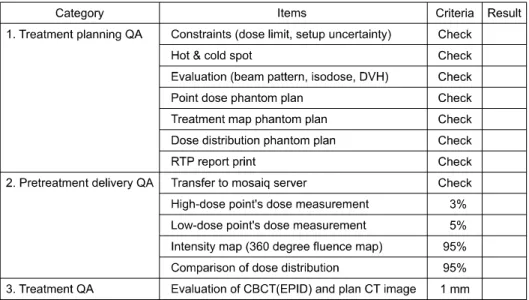
The items for the QA in VMAT patients were classified in- to three different QA steps, treatment planning QA, pretreat- ment delivering QA, and treatment verifying QA. Fig. 4 as a document that used in our hospital, shows a check box for each item and reference in clinical treatment acceptance. Also, seven items had to be checked to verify the treatment planning QA procedure. The result showed that three treatment plans were required and involved the use of different phantoms and
instruments for point dose QA, treatment map QA, and iso- dose distribution QA. In the future, there is a plan to integrate the treatment plan check items because the measurement of point doses and the evaluation of isodose distributions will be performed by using an intra-cavity adapter inside the ArcCheck system to improve its performance. Moreover, four check items were set-up for the pretreatment delivering QA, and the check items of the treatment information delivery in the Mosaiq database server were set-up for a tool of the ac- ceptable result. Excepting above four check items, the accept- ance values for the other three items satisfied with the value of confidence limit 95% were set-up. One check item that was compared to the difference between the cone-beam CT images and the plan CT images was determined in the treatment QA.
In our hospital, the QA items were determined so that the treatment points in patients were to be examined using the cone-beam CT images at the first treatment; additional checks were performed once a week after starting the treatment.
2. Configuration of the acceptance reference for the quality assurance items
Table 1 shows the characteristics of patients and treatment
plans for the six clinical cases evaluated in this study. The
measurement of point doses, the analysis of intensity maps,
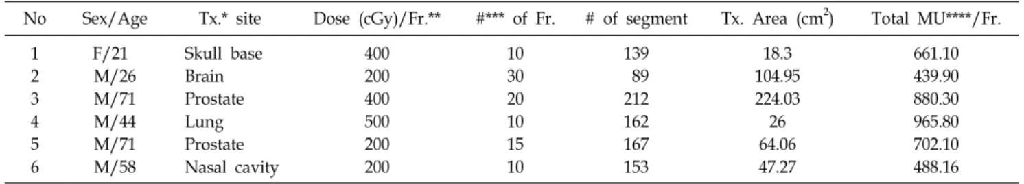
Fig. 5. The example of dosimetric QA. (a) The 360-degree intensity-map evaluation with ArcCheck. (b) The isodose distribution
evaluation with MapCheck.Fig. 6. The graph shows the evaluation results of the patient
setup with CBCT and CT simulation images.and the investigation of isodose distributions performed at the pretreatment delivery step for the six treatment plans are listed in Table 2. In the results of this study, all CL values were re- corded within 3%, with a maximum of −2.52% and an aver- age of 0.95%, in the high-dose region. In the low-dose region, all CL values satisfied the reference within 5% with a max- imum of 4.66% and an average of 2.04%. The results of the calculation of the local CLs for the high-dose and the low-dose regions were 3.79% and 5.09%, respectively.
Regarding the results of the calculation of the CLs performed by 10 organizations in the case of conventional IMRT, the minimum local, maximum, and average CLs were recorded as 2.5%, 6.8%, and 4.5%, respectively. Regarding the results of the calculation of CLs performed by 9 organizations for the low-dose region, the minimum, maximum, and average CLs were recorded as 1.4%, 8.6%, and 4.7%, respectively.
6)In the local CL results, the measurements of point doses in the high-dose and the low-dose regions performed in our hospital produced similar results to those for IMRT. Thus, the accept- ance references in practical clinical applications for the high-dose and the low-dose regions were determined as 3 and 5%, respectively, the same as those for IMRT.
Fig. 5 shows MapCheck software image of the comparison and evaluation of gamma indexes using ArcCheck and MapCheck. In the evaluation of intensity maps for all direc- tions 360
o, the maximum and the average records were 5.9%
and 3.55%, respectively. Also, the local acceptance level was
calculated as 7.17%. The Gray A group used MapCheck at five organizations, and EPID at one organization. In these measurements, the acceptance references were presented as a level of 7.0%, which is similar to that of the local acceptance reference determined at our hospital. In the evaluation of the isodose distribution using MapCheck, the maximum and the average CL records were 3.1% and 0.8%, respectively. Also, the local acceptance level was calculated as 3.93%. In the case of the Gray A group for IMRT, the results were around 88%.
Its lower values were result from including the film dosimetry.
Thus, in our hospital, the acceptance references used in prac-
tical clinical application for the intensity maps of 360
odirec-
tions and the coronal isodose distributions were determined to
be 93% and 95%, respectively.
Fig. 6 shows the results of a comparison between the cone beam CT images and the plan CT images, where these images were determined as items for treatment QA. In our hospital, the cone beam CT images were obtained once a week during the treatment period, and the patient’s treatment position was corrected when the difference in position was more than 1 mm in any direction. As the image acquisition intervals were ad- justed based on the characteristics of the patients and on their treatment points, in case 4, the treatment position was cor- rected by obtaining images twice a week based on these characteristics.
DISCUSSION AND CONCLUSION
In this work, the QA items considered in VMAT among the items were proposed by using the conventional literature and the IMRT was determined in order to develop the items for the QA in VMAT treatments as a new radiation treatment method. The selected QA items were classified into three steps, treatment planning QA, pretreatment delivery QA, and treatment QA. The items developed in each step were docu- mented to apply them in practical clinical situations, and the clinical application acceptance values were also evaluated. For determining the items for the pretreatment delivery QA, we evaluated the CLs employed in our hospital by comparing and analyzing the CL data presented in the conventional IMRT ac- ceptance examination. To reduce arbitrary uncertainties and system errors, we had to evaluate the local CLs by using a phantom and to have multiple organizations participate in this evaluation. In addition, we had to evaluate the local CLs by dividing them into different sections about the patient treat- ment points in practical clinics. Even though the method in this study was a rotational treatment method, the results of the accuracies for the gantry angle, dose rate arcs, MLC leaf speed and position, were similar to those of the conventional IMRT. Also, the ArcCheck was an appropriate device for ver-
ifying the fluence map of 360
odirections, particularly accuracies. In the future, the confidence limits of other ma- chines in Korea, such as Tomotherapy and RapidArc should be considered through the participation of multiple organizations.
REFERENCES
1. Webb S: Contemporary IMRT: Developing physics and clinical applications. Bristol, UK: Institute of Physics Publishing (2005) 2. Otto K: Volumetric modulated arc therapy: IMRT in a single
gantry arc. Med Phys 35:310-317 (2008)
3. Ezzell GA, Galvin JM, Low D, et al: Guidance document on delivery, treatment planning, and clinical implementation of IMRT: Report of the IMRT subcommittee of the AAPM radiation therapy committee. Med Phys 30:2089-2115 (2003)
4. Kutcher GJ, Coia L, Gillin M, et al: Comprehensive QA for radiation oncology: Report of AAPM Radiation Therapy Committee Task Group 40. Med Phys 21:581-618 (1994)
5. Kirby M, Ryde S, Hall C: Acceptance testing and commis-
sioning of linear accelerators. Institute of Physics and Engineering
in Medicine, York, UK. (2006), pp. 536. Ezzell GA, Burmeister JW, Dogan N, et al: IMRT com- missioning: Multiple institution planning and dosimetry compar- isions: Report of AAPM Task Group 119. Med Phys 36:5359- 5373 (2009)
7. Hansen VN, Evans PM, Budgell GJ, et al: Quality assur- ance of the dose delivered by small radiation segments. Phys Med Biol 43:2665-2675 (1998)
8. Sharpe MB, Miller BM, Yan D, et al: Monitor unit settings for intensity modulated beams delivered using a step-and-shoot approach. Med Phys 27:2719-2725 (2000)
9. Palta JR, Mackie TR: Intensity modulated radiation ther- apy-The state of the art Medical Physics. Madison, WI, (2003), pp.593
10. Bedford JL, Webb S: Direct-aperture optimization applied to selection of beam orientations in intensity-modulated radiation therapy. Phys Med Biol 52:479-498 (2007)
11. Spirou SV, Chui CS: Generation of arbitrary intensity profiles by dynamic jaws or multileaf collimators. Med Phys 21:1031-1041 (1994)
12. Low DA, Harms WB, Mutic S, et al: A technique for the quantitative evaluation of dose distributions. Med Phys 25:656- 661 (1998)
13. Bedford JL, Webb S: Direct-aperture optimization applied to selection of beam orientations in intensity-modulated radiation therapy. Phys Med Biol 52:479-498 (2007)
Elekta Synergy 선형가속기를 이용한 입체적세기조절회전방사선치료(VMAT) 정도관리
*을지대학교 의과대학 방사선종양학과,
†고려대학교 의과대학 방사선종양학과,
‡
관동대학교 의과대학 제일병원 방사선종양학과,
§순천향대학교 의과대학 방사선종양학과,
∥
경희대학교 의과대학 방사선종양학과,
¶가천대학교 길병원 방사선종양학과,
#