Viscoelastic Analysis of an Interface Edge Crack in a Bonded Polymeric Film
Sang Soon Lee
††
Korea University of Technology and Education, School of Mechatronics Engineering
ABSTRACT
Interfacial stress singularity induced in an analysis model consisting of the polymeric thin film and the elastic substrate has been investigated using the boundary element method. The interfacial singular stresses between the viscoelastic thin film and the elastic substrate subjected to a uniform moisture ingression are investigated for the case of a small interfacial edge crack. It is assumed that moisture effects are assumed to be analogous to thermal effects. Then, the overall stress intensity factor for the case of a small interfacial edge crack is computed. The numerical procedure does not permit calculation of the limiting case for which the edge crack length vanishes.
Key Words : Interfacial stress singularity, Polymeric film, Elastic substrate, Edge crack, Boundary element method
1. Introduction
Polymeric films such as polyimide or epoxy are widely used in semiconductor industry as dielectric insulating layers or adhesive layers. Thin films depos- ited on a SI substrate absorb moisture from the ambi- ent environment, which induces swelling strains into films. Polymeric films are hygroscopic and absorb large quantities of water. In the presence of water, adhesion of polymeric film to substrates such as glass and aluminum tends to fall off rapidly. It is well known that a stress singularity exists at the interface corner between perfectly bonded quarter planes and such high stress intensification may lead to edge cracks or local delamination [1-5].
The mechanics of cracks at a bi-material interface has been investigated by several authors [6-8]. The oscillation of stresses or the overlapping of crack sur- faces near the interface crack tip occurs although the boundary condition of crack surface is taken as trac- tion free. As several investigators indicated, however, the oscillation region can usually ignored, since such region is confined to the extremely small region near the crack tip. Classical methods for the analysis of
interface crack problems are limited to a few special cases, due to the complexity of the solution procedure for the interfacial singular problem.
The boundary element method (BEM) has been shown to be a useful and effective numerical tech- nique for analyzing interface problems [9-11]. The focus of the present study is on the computation of the characteristic complex stress intensity factor for an edge crack at the epoxy film- SI substrate interface using BEM. Polymeric films in general exhibit time and moisture dependent properties. The interfacial singular stresses between the viscoelastic thin film and the elastic substrate subjected to a uniform mois- ture ingression are investigated for the case of a small interfacial edge crack of length . It is assumed that moisture effects are assumed to be analogous to ther- mal effects. Then, the overall stress intensity factor for the case of a small interfacial edge crack is com- puted.
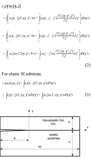
2. Boundary Element Analysis The problem for an edge crack at the interface between the viscoelastic epoxy film and the elastic SI substrate is to be solved. The analysis model is shown in Fig. 1. The ingression of moisture provides the only loading. Calculations are performed for (W−a)>8h.
†E-mail : [email protected]
It is assumed that moisture effects are analogous to thermal effects. A uniform moisture change ∆mH(t) in the film is equivalent to increasing the tractions by [12] where
γ(t) = 3Kβ∆mH(t) (1)
Here, K is the bulk modulus; n
jare the components of the unit outward normal to the boundary surface; and β is the coefficient of hygral expansion of the viscoe- lastic epoxy film.
With a uniform moisture change in the film, it is convenient to write the boundary integral equations with respect to reduced time ξ. Then, the boundary integral equations without any other body forces are written as follows [12]:
For viscoelastic thin film, c
ij(y)u
j(y,ξ)
(2) For elastic SI substrate,
(3)
where u
jand t
jrepresent displacement and traction, and S is the boundary of the given domain. c
ijis dependent only upon the local geometry of the boundary. For y on a smooth surface, the free term c
ijis simply a diagonal matrix 0.5δ
ij. The viscoelastic fundamental solutions, U
ijand T
ij, can be obtained by applying the elastic-viscoelastic correspondence prin- ciple to Kelvin’s fundamental solutions of linear elas- ticity.
In Eq. 2, ξ is the reduced time defined as follows:
(4)
where χ is the shift function, a function of moisture cycle. Under the constant moisture change ∆mH(t) the reduced time ξ of Eq. 4 becomes
ξ = χt (5)
Eqs. 2 and 3 can be solved in a step by step fashion in time by using the modified Simpson’s rule for the time integrals and employing the standard BEM for the surface integrals. Solving Eqs. 2 and 3 under boundary conditions leads to determination of all boundary displacements and tractions.
The following viscoelastic model for the film is employed in this study.
MPa (6)
K(t) = 3600 MPa (7)
where is a tensile relaxation modulus, is a bulk modu- lus. The values of E
iand β
iare listed in Table 1.
The numerical values used in this example are as follows:
∆m = 2%, β = 0.001/%, χ = 5 (8)
The numerical values used for the elastic substrate are as follows:
k = 210 GPa, ν = 0.29 (9)
u
j( y' ξ , )T
ij( y y' 0 , ; ) u
j 0+ξ
∫ ( y' ξ ξ ' , – ) ∂T ---dξ '
ij( y y' ξ ' ∂ξ ' , ; )
+ d S y' ( )
∫
s+
t
j( y' ξ , )U
ij( y y' 0 , ; ) t
j 0+ξ
∫ ( y' ξ ξ ' , – ) ∂U ---dξ '
ij( ∂ξ ' y y' ξ ' , ; )
+ d S y' ( )
∫
s=
γ ξ ( )n
jU
ijm( y y' 0+ , ; ) γ
0+
ξ
∫ ( ξ ξ ' – )n
j∂U ---dξ '
ij( ∂ξ ' y y' ξ ' , ; )
+ d S y' ( )
∫
s+
c
ij( )u y
j( y ξ , ) u
j( y' ξ , )T
ij( y y' , ) S y' d ( )
∫
s+
t
j( y' ξ , )U
ij( y y' , ) S y' d ( ) γ ξ ( )n
jU
ij( y y' , ) S y' d ( )
∫
S+
∫
S=
ξ ξ t ( ) χ m ρ ( ( ) ) ρ d
0 t
∫
= =
E ξ ( ) E
0E
iξ
β
i– ---- exp
t 1= 14
∑
+
=
Fig. 1. Boundary element analysis model.
3. Stress Intensity Factor for an Interfacial Crack
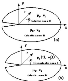
An interface crack in dissimilar elastic materials is shown in Fig. 2(a). The stresses near the interface crack tip are given as follows [8] :
(10) where r is the distance from the crack tip, d is the arbitrary length to normalize the distance r in the log- arithmic term, and . K
1and K
2are the com- ponents of the complex stress intensity factor of the interface crack,
(11) (12)
κ
i= 3 − 4ν
i(13)
κ
II= 3 − 4ν
II(14)
The µ and ν are the shear modulus and Poisson’s ratio and the subscript denotes each material.
The stress field near an interface crack between lin- ear elastic material and linear viscoelastic material (Fig. 2(b)) can be obtained by applying the elastic- viscoelastic correspondence principle to Eq. 10. The stress distribution on θ = 0 in the Laplace transformed space is given as follows:
(15) (16)
(17)
(18) (19) Here and are the Laplace transformed viscoelastic stresses, and are the Laplace transformed stress intensity factors, and is the trans- form variable. and are Laplace trans- forms of the shear relaxation modulus and the viscoelastic Poisson’s ratio .
As can be seen from Eq. 15, the stresses exhibit an
σ
yy( r θ , ) iτ +
xy( r θ , )
[ ]
θ 0=K
1+ iK
2--- 2πr iβ r d ---
⎝ ⎠ ⎛ ⎞ ln exp
=
i = – 1
β 1
2π --- ln ( ) γ
=
γ κ
Iµ
II+ µ
Iκ
IIµ
I+ µ
II---
=
σ
yy( r θ s , ; ) iτ +
xy( r θ s , ; )
[ ]
θ 0=K
1+ iK
2--- 2πr iβ s ( ) r d ---
⎝ ⎠ ⎛ ⎞ ln exp
=
β s ( ) 1 2 --- ln [ γ s ( ) ]
=
γ κ
I( )µ s
II+ sµ
I( ) s κ
IIsµ
I( ) µ s +
II---
=
κ
I( ) s = 3 4sν –
I( ) s κ
II= 3 4ν –
IIσ
yy( ) s τ
xy( ) s
K
1( ) s K
2( ) s µ
I( ) s ν
I( ) s
µ
I( ) s Table 1. The constants of Eq. 6
β
i(min) E
i(MPa)
0.5 × 10
140.10817 E+0.3
0.5 × 10
130.12935 E+0.3
0.5 × 10
120.18168 E+0.3
0.5 × 10
110.23739 E+0.3
0.5 × 10
100.28994 E+0.3
0.5 × 10
90.32514 E+0.3
0.5 × 10
80.33116 E+0.3
0.5 × 10
70.30568 E+0.3
0.5 × 10
60.25760 E+0.3
0.5 × 10
50.20145 E+0.3
0.5 × 10
40.14720 E+0.3
0.5 × 10
30.10934 E+0.3
0.5 × 10
20.48615 E+0.2
0.5 × 10 0.15854 E+0.3
Fig. 2. Region near crack tip along bi-material interface.
oscillating singularity. However, the maximum ampli- tude of these singular stresses is determined by the overall stress intensity factor as follows:
(20) where represents the overall stress intensity factor in the transformed space. In terms of stresses, it can be easily verified that
(21) of Eq. 21 can be inverted into the real space as follows:
(22) The overall stress intensity factor for the elas- tic-viscoelastic interface crack can be determined from the stresses near the crack tip using Eq. 22. It is well known that by using the quarter-point element for displacement fields and the traction singular quar- ter-point element for the traction field, the variation of the displacements and tractions along the crack tip element is of the correct order as those established in fracture mechanics theory [10,11]. The stress inten- sity factor can be expressed from Eq. 22 as
(23) where denotes the BEM computed traction on the traction singular crack tip element at the crack tip node and is the length of the crack tip element.
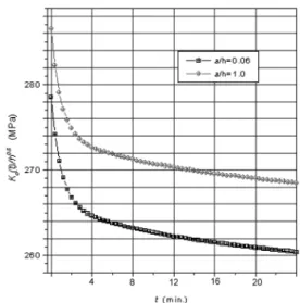
The problem for an edge crack at the interface between the viscoelastic film and the elastic substrate subjected to a uniform moisture ingression is solved.
The analysis model is shown in Fig. 1. Fig. 3 shows the BEM results of K
O(t) for crack lengths a/h = 0.06, 1.0, in which K
O(t) for each crack length is relaxed with time. K
O(t) is seen to decrease with decreasing crack size. To begin with, at time t = 0, if is more than the critical value K
C, the crack starts growing before it reaches a stage where K
O(t) drops below that of K
Cand then it ceases to grow. In another situation, right at the beginning, if K
Ois below the critical value K
C,
the crack will never grow.
The crack tip elements are used with small crack tip element to crack length ratios (L/a) to represent prop- erly both the displacement behavior and 1/
traction behavior. As (a/b<10
-3), however, the boundary element procedure is inaccurate due to the instability of the crack tip elements to represent the stress singularity. This means that the numerical pro- cedure does not permit calculation of the limiting case for which the edge crack length vanishes.
4. Conclusions
Interfacial stress singularities induced in a laminate model consisting of the viscoelastic thin film and the elastic substrate as the film absorbs moisture from the ambient environment have been investigated using the boundary element method. The overall stress intensity factor for an interfacial edge crack at the interface between the viscoelastic film and the elastic substrate subjected to a uniform moisture ingression has been computed using the tractions at the crack tip node. The magnitude of stress intensity factors decreases with time due to viscoelastic relaxation, but remains constant at large times. At time t = 0, if the overall stress intensity factor is more than the critical value, the crack starts growing before it reaches a stage where the overall stress intensity factor drops K
O( ) s = K s ( ) = K
1( ) s
2+ K
2( ) s
2K
O( ) s
K
O( ) s 2πr σ [
yy( r 0 s , ; ) ]
2+ [ τ
xy( r 0 s , ; ) ]
2r→0
= lim
K
O( ) s
K
O( ) t 2πr σ [
yy( r 0 t , ; ) ]
2+ [ τ
xy( r 0 t , ; ) ]
2r→0