VHDL을 이용한 시스터메틱 LT 부호의 구현
장매향*, 김수영* 종신회원, 장진영**, 김원용**
Implementation of systematic LT codes using VHDL
Meixiang Zhang*, Sooyoung Kim* Lifelong Member, Jin Yeong Chang**, Won-Yong Kim**
요 약
Luby transform (LT) 부호는 무율(rateless) 부호의 하나로써, 주어진 정보 길이에 대해 이론적으로 무한대의 부호어를 생성해 낼 수 있도록 설계된 부호이다. 이와 같은 무율부호는 방송 및 멀티캐스팅 서비스에서 수신자 별로 서로 다른 채널의 상황에 대비하여 사용될 수 있다는 점에서 효과적인 방식이다. 위성 시스템에서도 이와 같은 무율부호를 적용하는 여러 가지 경우에 대하여 연구가 진행 중이다. 본 논문에서는 이와 같은 연구 추세를 감안하여 무율부호 중 가장 먼저 개발된 LT 부호에 대한 하드웨어 구현을 위하 여, VHDL을 이용하여 LT 부호의 구현 결과를 소개한다. 본 논문에서 제시된 결과는 향후 위성 시스템에서 무율 부호가 효과적으로 활용될 수 있는 기초적인 자료로 활용될 것이다.
Key Words : LT codes, rateless codes, VHDL, satellite broadcasting, DVB-S.
ABSTRACT
Luby transform (LT) codes are a class of ratelss codes, and they have capability of generating infinite length of parities with a given information length. These rateless codes can be effectively utilized to provide broadcasting and multicasting services where each user is in a different channel condition. For this reason, there have been a number of researches on the application of rateless codes for satellite systems. In this paper, by considering the current research status on rateless codes, we present VHLD implementation results of LT codes, for future hardware implementation for satellite systems. The results demonstrated in this paper can be utilized as a basic information on efficient utilization of rateless codes in the future satellite systems.
※ 본 연구는 미래창조과학부 및 정보통신산업진흥원의 IT/SW 창의연구과정의 연구결과로 수행되었음 (NIPA-2013-H0502-13-1090)
*전북대학교 전자공학부 IT융합연구센터 ([email protected], [email protected]),
**(주)코메스타 ([email protected], [email protected]), 교신저자 : 김수영
접수일자 : 2014년 5월 6일, 수정완료일자 : 2014년 5월 26일, 최종게재확정일자 : 2014년 5월 30일
I. Introduction
Luby transform (LT) codes were first proposed as rateless codes, and were designed to obtain capacity-achieving performance for a binary erasure channel (BEC) without knowing the erasure conditions [1].
LT codes are rateless codes because the number of encoding symbols can be generated from the information symbols is limitless. With rateless codes, every receiver can access the ongoing broadcast session at arbitrary time and receive the message with the required quality of service (QoS), independent of the channel condition.
Multimedia broadcast multicast services (MBMS) introduced in the third Generation partnership project
(3GPP) uses forward error correction (FEC) scheme with rateless codes at the application layer to protect the video bit stream against packet loss [2]. The satellite system is an effective means to provide MBMS, and thus rateless codes are considered to provide satellite broadcasting services efficiently. For example, in order to overcome the heterogeneity and reduce the number of retransmissions, the packet level forward error correction (FEC) scheme using LT codes was incorporated in satellite data broadcasting system in [3]. Applications of raptor codes for the digital video broadcasting via satellite (DVB-S) system were considered in [4][5].
In this paper, we present an implementation result of the encoder and decoder for LT codes [1], using VHSIC
Hardware Description Language (VHDL) [6], for possible application to future satellite systems. The reminder of this paper is organized as follows. Section II reviews the encoding and decoding for LT codes. Section III presents the block diagrams for hardware implementation of the encoding and decoding process. Simulation results are given in section IV. Conclusion is drawn in section V.
Ⅱ. Encoding and Decoding of LT codes
1. Encoding of LT codes
The encoding process of LT codes is performed repeatedly by using a given degree distribution [1]. First, the degree for the encoding symbol is generated randomly according to the given degree distribution [7].
Second, distinct information symbols are chosen uniformly as neighbors of the encoding symbol. Third, the value of the encoding symbol is calculated by the exclusive-or of the neighbors. Figure 1 shows the concept of encoding.
Fig. 1. Encoding process for LT codes
2. Decoding of LT codes
The decoding for LT codes are performed by iterative exchange of information on the Tanner graph as shown in Fig. 2. With this Tanner graph, LT decoding is performed using the belief propagation algorithm [1].
At the first step all encoding symbols with a single neighbor are released to cover the unique neighborhood information symbol using its value. At each subsequent step the information symbol that has been covered is processed as: it is removed as a neighbor from all encoding symbols which has it as a neighbor and its value is exclusive-ored to all of its neighbors. Then all such encoding symbols that subsequently have exactly one remaining neighbor are released to cover their remaining
neighborhood information symbol. This process is repeated until there is no encoding symbol which only has one neighbor. The process succeeds if all information symbols are coved at the end of the decoding process.
Fig. 2. Tanner graph for LT codes
Ⅲ. Structures of the Encoder and Decoder
1. Basic structure of encoder for VHDL implementation
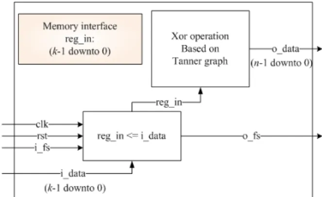
Figure 3 shows the block diagram of encoder for LT codes. There are four inputs of "clk", "rst," "i_data", and
"i_fs", which represent signal for clock, reset, input data, and input frame sink, respectively. There are two outputs of "o_data" and "o_fs", which represent output data and output frame sink, respectively. As we can see from Fig.
3, after receiving input data "i_dadta" with length of , it is saved to a buffer memory "reg_in" which is used to calculate the output data with length of using exclusive-or operation based on the Tanner graph.
Fig. 3. Block diagram of encoder for LT codes
2. Basic structure of decoder for VHDL implementation
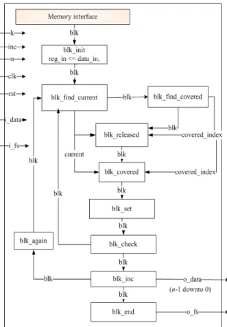
Figure 4 shows the basic structure of decoder for LT codes. There are seven inputs and two outputs. The input
"k", "inc" and "n" represent the information length, the incremental information length and the maximum codeword length, respectively. Inputs "i_data" and "i_fs"
are input data with length "n" and input frame sink, and
"clk" and "rst" are the same as the ones used in the encoder in Fig. 3. Outputs "o_data" and "o_fs" represent output data with length "k" and output frame sink, respectively.
Fig. 4. Block diagram of decoder for LT codes
In Fig. 4, we can see that after the memory allocation, the block "blk_init" is performed under signal "blk", where the function of "blk_init" is to initialize the decoder for LT codes. Afterwards, each functional block will be performed under the signal "blk" to make sure the sequential execution under the corresponding condition. The functional block "blk_find_current" is performed to find the index of encoding symbol, "current", which has only one neighborhood information symbol. On the other hand, the block "blk_find_covered" is performed to find the index of
information symbol, "covered_index", which is the unique neighbor of the encoding symbol "current" found by the block "blk_find_current".
Using these indexes for encoding symbol and information symbol, the functional block "blk_released" is performed to disconnect them and cover the information symbol "covered_index" using the encoding symbol
"current". Subsequently, the functional block "blk_covered"
is performed to disconnect the information symbol
"covered_index" with all remaining encoding symbols which have it as a neighbor and its value is exclusive-ored to these neighborhood encoding symbols.
The function of the block "blk_set" is to reset the local signals which makes each block to be performed in a sequential way. Afterwards, the functional block
"blk_check" is used to check if there is any remaining encoding symbols with a single neighbor. Depending on the result, the functional block "blk_inc" or
"blk_find_current" is used. The functional block "blk_inc"
is performed to examine if all the information symbols has been covered. If all the information symbols are covered, then the block "blk_end_inc" is performed, otherwise the block "blk_again" is performed. In the block "blk_again", more data with length of "inc" will be collected and the decoder will be initialized for the next decoding attempt.
Block "blk_end_inc" is used to terminate current decoding attempt if the decoding is succeeded or it all the received encoding symbols are used.
Ⅳ. Simulation results
1. Timing simulation results
We implemented the LT code with information length
=12, and the maximum codeword length =24 with the distribution in [7], using the software MODELSIM [8]. In the decoding process, if the LT decoding fails with the length of encoding symbols is 12, then more encoding symbols with length "inc=6" will be collected. Taking these encoding symbols with length of 12+6=18, the decoding attempt is performed again. This process is repeated until the decoder recovers all the information symbols or the maximum number of encoding symbols has been received.
Figure 5 shows an example of timing simulation results for LT encoding process. From Fig. 5, when input frame sink "i_fs" is changed to 1, input data "i_data" is received.
At the falling edge of the clock, "o_data" representing the codeword is calculated and output frame sink "o_fs" is assigned to 1 at the same time.
Fig. 5. An example of timing simulation results for LT encoding
Figure 6-14 show the examples of timing simulation results for each sub-blocks of LT decoding process. In Fig. 6, before input frame sink "i_fs" is changed to 1, every signal was initialized with the corresponding value.
When the input frame sink "i_fs=1", input data representing the received codeword with length of 24 is received as shown in "data_in".
Figure 7 shows an example of timing simulation results after processing block "blk_init". After being performed, input data "data_in" with length of is saved to a buffer memory "reg_in" and block index "blk" is changed to
"blk_find_current".
Fig. 6. An example of timing simulation results for input frame sink
Figure 8 shows an example of timing simulation results for block "blk_find_current". After it is performed, an encoding symbol with index "current = 17" in hexadecimal is found, and block index "blk" is changed to
"blk_find_covered" at the same time.
Fig. 7. An example of timing simulation results for
"blk_init"
Fig. 8. An example of timing simulation results for
"blk_find_current"
Figure 9 shows an example of timing simulation results for "blk_find_covered". After it is performed, an information symbol with index "covered_index = B" in hexadecimal is found, and block index "blk" is changed to
"blk_released".
Fig. 9. An example of timing simulation results for
"blk_find_covered"
Figure 10 shows an example of timing simulation results for block "blk_released". Using the indexes
"current" and "covered_index" found in block
"blk_find_current" and block "blk_find_covered", the information symbol with index "covered_index = B" in hexadecimal is updated as shown in "reg_out", and block index "blk" is changed to "blk_covered" at the same time.
Fig. 10. An example of timing simulation results for
"blk_released"
Figure 11 shows an example of timing simulation results for block "blk_covered". After it is performed, the encoding symbols which are the neighbors of information symbol with index "covered_index = 0" in hexadecimal is updated as shown in "reg_in" in Fig. 11. Figure 12 shows an example of performing blocks of "blk_set", "blk_check"
and "blk_find_current" in order.
Figure 13 shows an example of timing simulation results for block "blk_again". In block "blk_again" more encoding symbols with length of "inc=6" bits will be copied to "reg_in" and the current length of the codeword
"flen" is changed to "12" from "C" in hexadecimal. After it is performed, the block index "blk" is changed to
"blk_find_current" to control the program to repeat the decoding procedure.
Fig. 11. An example of timing simulation results for
"blk_covered"
Fig. 12. Examples of processing of sub-blocks
Fig. 13. An example of timing simulation results for
"blk_again"
Figure 14 shows an example of timing simulation results for blocks "blk_check", "blk_inc", and
"blk_end_inc" in order. After block "blk_check" is performed, output data is updated as shown in "data_out".
Block index "blk" is changed to "blk_end_inc" after block
"blk_inc" is performed.
Fig. 14. An example of processing sub-blocks
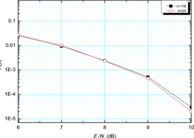
4.2 Frame error rate (FER) simulation results
Figure 15 shows the performance of frame error rate (FER ) according to symbol energy to noise ratio ()
with the maximum codeword length of =18 and =24.
Figure 15 shows that the decoding performance is increased with increase in . Because the decoding algorithm implemented for LT codes is hard decision decoding based, the performance difference according to not large. The performance of the decoding can be enhanced if a soft iterative decoding algorithm is utilized [9].
Fig. 15. FER performance simulation results for systematic LT codes
V. Conclusion
In this paper, we presented a method of implementing the encoding and decoding for LT codes using VHDL. The simulation results demonstrated in this paper showed valid timing and functional operation of the implemented results.
In order to enhance the decoding performance, we may utilize iterative soft decoding algorithm in our future research.
참 고 문 헌
[1] M. Luby, “LT codes”, Proceedings of 43rd Annual IEEE Symp. on the Found. of Comp., pp. 271-280, 2002.
[2] Raouf Hamzaoui, Shakeel Ahmad, and Marwan AL-Akaidi,
“Reliable Wireless Video Streaming with Digital Fountain Codes”, pp. 1-17.
[3] Hongpeng Zhu, Guangxia Li, and Zhidong Xie, “Advanced LT codes in Satellite Data Broadcasting System”, Proceedings of 11th IEEE Singapore International Conference on Communication Systems, pp. 1430-1435, Nov.
2008.
[4] Pasquale Cateldi, Mario Gerla, and Francesco Zampognaro,
“Rateless Codes for File Transfer over DVB-S”,
Proceedings of First International Conference on Advances in Satellite and Space Communications, pp. 7-12, Jul. 2009.
[5] Mohammad Jabbari Hagh and M. Reza Soleymani,
“Constellation Rotation for DVB Multiple Access Channels with Raptor coding”, IEEE Transactions on Broadcasting, vol. 59, no. 2, pp. 290-297, Jun. 2013.
[6] http://www.csee.umbc.edu/portal/help/VHDL/VHDL- Handbook.pdf [7] Hu, Jeff Castura, and Yongyi Mao, “Performance- Complexity Tradeoffs of Raptor Codes over Gaussian Channels”, IEEE Communication Letters, vol. 11, no. 4, pp.
343-345.
[8] http://www.mentor.com/products/fpga/model
[9] H. Jenka, T. Mayer, T. Stockhammer, and W. Xu, “Soft Decoding of LT-codes for Wireless Broadcast,” in Proc. IST Mobile, Dresden, Germany, 2005
저자
장 매 향 (Meixiang Zhang)
․2009년 7월:중남민족대학교 컴퓨터공 학 학사졸업
․2012년 8월:전북대학교 전자 공학부 석사졸업
․2012년 9월~현재 : 전북대학교 전자공 학부 박사과정
<관심분야> : 위성통신, 디지털 통신, 오류정정부호방식, 연 판정 검출, 무율부호
김 수 영 (Sooyoung Kim) 종신회원
․1990년 2월:한국과학기술원 전기 및 전자공학과 학사졸업
․1990년~1991년:ETRI 연구원
․1992년:Univ. of Surrey, U.K 공학석사
․1995년:Univ. of Surrey, U.K 공학박사
․1994년~1996년:Research Fellow, Univ. of Surrey, U.K
․1996년~2004년:ETRI 광대역무선전송연구팀장
․2004년~현재:전북대학교 전자공학부 교수
<관심분야> : 오류정정부호화방식, 이동/위성통신 전송방식
장 진 영 (Jin Yeong Chang)
․2003년 2월 : 전북대학교 정보통신공학 과 학사
․2005년 8월 : 전북대학교 정보통신공학 과 공학석사
․2005년 12월~현재 : (주) 코메스타 통 신사업부 부장
<관심분야> : 이동/위성통신
김 원 용 (Won-Yong Kim)
․1995년 2월 : 전남대학교 전자공학과 학사
․1997년 2월 : 전남대학교 전자공학과 공학석사
․1997년 3월~2000년 10월 : (주) 대우 통신 선임연구원
․2000년 11월~2002년 12월 : (주) 머큐리 선임연구원
․2003년 1월~현재 : (주) 코메스타 연구소장 <관심분야> : 이동/위성통신, 대역확산 방식