- 40 -
Design and Construction of 10 kWh Class Flywheel Energy Storage System
S. Y. Jung
*, S. C. Han, Y. H. Han, B. J. Park, Y. C. Bae, W. R. Lee
KEPCO Research Institute, Daejeon, Korea
(Received 13 July 2011 revised 29 July 2011 accepted 1 August 2011)
10 kWh급 플라이휠 에너지 저장 시스템 설계 및 제작
정세용
*, 한상철, 한영희, 박병준, 배용채, 이욱륜
Abstract
A superconductor flywheel energy storage system (SFES) is an electro-mechanical battery which transforms electrical energy into mechanical energy for storage, and vice versa. A 10 kWh class flywheel energy storage system (FESS) has been developed to evaluate the feasibility of a 35 kWh class SFES with a flywheel Ip/It ratio larger than 1. The 10 kWh class FESS is composed of a main frame, a composite flywheel, active magnetic dampers (AMDs), a permanent magnet bearing, and a motor/generator. The flywheel of the FESS rotates at a very high speed to store energy, while being levitated by a permanent magnetic bearing and a pair of thrust AMDs. The 10 kWh class flywheel is mainly composed of a composite rotor assembly, where most of the energy is stored, two radial and two thrust AMD rotors, which dissipate vibration at critical speeds, a permanent magnet rotor, which supports most of the flywheel weight, a motor rotor, which spins the flywheel, and a central hollow shaft, where the parts are assembled and aligned to. The stators of each of the main components are assembled on to housings, which are assembled and aligned to the main frame. Many factors have been considered while designing each part of the flywheel, stator and frame. In this study, a 10 kWh class flywheel energy storage system has been designed and constructed for test operation.
Keywords : superconductor, flywheel, energy, storage
I. Introduction
A superconductor flywheel energy storage system (SFES) is an electro-mechanical battery with high energy storage density, long life, and good environmental affinity. An SFES mainly consists of a
pair of non-contacting high temperature superconductor (HTS) bearings that provide very low frictional losses, a composite flywheel with high energy storage density and mechanical strength, a motor/generator that transfers mechanical energy into electrical form and vice versa, and a vacuum chamber that minimizes windage losses. The HTS bearings, which offer dynamic stability without active control, are the key technology that distinguishes the SFES from other flywheel energy
*Corresponding author. Fax : +82 42 865 5679 e-mail : [email protected]
storage devices, and great effort is being put into developing this technology [1-4].
A 5 kWh class SFES, with a flywheel Ip/It ratio of 0.6, has been constructed and test operated by KEPCO Research Institute [5]. A flywheel with an Ip/It ratio of less than 1 has favorable vibration control properties compared to a flywheel with an Ip/It ratio larger than 1, due to a lower strength of gyroscopic moment. On the other hand, a flywheel with an Ip/It ratio of less than 1 has lower energy storing capacity, due to lower specific energy density.
A 10 kWh class flywheel energy storage system (FESS), with a flywheel of Ip/It ratio larger than 1 for higher energy storing capacity, has been developed to assess the feasibility of a 35 kWh class SFES with a flywheel of Ip/It ratio larger than 1. The 10 kWh class flywheel energy storage system was designed, manufactured and assembled, and the system is scheduled for test operation.
II. Design of 10 kWh Class FESS
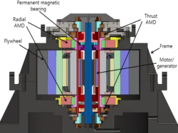
The 10 kWh class FESS, shown in Fig. 1, was designed according to the general specifications of Table 1. The system is a vertical axis outer rotor type, with a composite flywheel levitated by a permanent magnetic bearing and two thrust active magnetic dampers (AMDs), and rotated by a motor/generator in the inner part of the flywheel, and vibrations during critical speeds are dissipated by the radial AMDs.
Fig. 1. Cross-sectional view of 10 kWh class FESS.
Table 1. General specifications of 10 kWh class FESS.
Specification Value Unit
Stored energy 10 kWh
Max. operating speed 13,000 rpm Rotor Ip/It ratio 1.74 -
Hollow shaft 96 kg
Flywheel 448 kg
Inner diameter 490 mm
Outer diameter 970 mm
Rotor height 720 mm
Max. strength ratio 0.6 -
Design of Flywheel
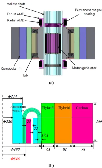
A 10 kWh class flywheel, as shown in Fig. 2, was designed and analyzed, and it is mainly composed of a composite rotor assembly, where most of the energy is stored, two radial AMD rotors, which dissipate vibration at critical speeds, a permanent magnet rotor and two thrust AMD rotors, which levitate the flywheel, a motor rotor, which spins the flywheel, and a central hollow shaft, where the parts are assembled and aligned to. The weight of the 10 kWh class composite rotor and hub assembly is 448 kg, with a diameter and height of 970 mm and 720 mm, respectively, and the maximum rotational speed is 13,000 rpm. The composite rotor is composed of three rims, each with different carbon and glass fiber compositions. The rims were press-fitted to reduce internal stress, and the resulting radial displacement and stress ratio at maximum speed were simulated (Fig.
3). The radial displacements at maximum speed are less than the interference values during assembly, that is, no separation between the composite rims will occur during operation. The maximum strength ratio at maximum speed is 0.6, that is, all deformations during operation are within elastic range.
(a)
(b)
Fig. 2. (a) Cross-sectional view and (b) dimensions of 10 kWh class composite flywheel.
(a)
(b)
Fig. 3. (a) Displacement and (b) stress ratio of composite rims at maximum speed.
The Ip/It ratio of a flywheel is the ratio of ‘polar inertia(Ip)’ and ‘transverse inertia(It)’. The flywheel is
‘pancake’ shaped when Ip is larger than It, and it is
‘cylindrically’ shaped when It is larger than Ip. If the Ip/It ratio is smaller than 1, the strength of the gyroscopic moment is small, so the flywheel is easier to control at high speeds and the system is more stable.
On the other hand, if the Ip/It ratio is larger than 1, specific energy density of the flywheel increases, allowing for more energy to be stored in the flywheel, thus, creating a more efficient system. The 5 kWh class SFES previously developed at KEPCO Research Institute employed a flywheel with an Ip/It ratio of 0.6, for stability reasons. To allow for a more economical and efficient model for the 35 kWh class SFES, the feasibility of a flywheel with an Ip/It ratio larger than 1 has to be evaluated. The composite flywheel for the 10 kWh class FESS has been designed with an Ip/It ratio of 1.74 to evaluate the possibility of applying a flywheel with an Ip/It ratio larger than 1 to the 35 kWh class SFES, which is scheduled to be developed at KEPCO Research Institute.
Design of Active Magnetic Dampers (AMDs) The radial active magnetic dampers (AMDs) of the 10 kWh class FESS were designed as 8-pole inner
rotor types, with dimensions shown in Fig. 4(a). At each pole, a coil of 90 turns is positioned to produce 3,800 N in the radial direction at 5 A of current, and 11,000 N at 10 A.
The thrust AMDs are positioned above the radial AMD in the upper side of the flywheel, as shown in Fig. 4(b), and below the radial AMD in the lower side of the flywheel. A coil of 180 turns is assembled to the thrust AMD stator, to produce 2,000 N in the radial direction at 5 A of current, and 7,200 N at 10 A.
(a)
(b)
Fig. 4. (a) Radial and (b) thrust AMD dimensions.
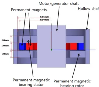
Design of Permanent Magnetic Bearing
The dimensions of the permanent magnetic bearing of the 10 kWh class FESS are shown in Fig. 5. The permanent magnets of the permanent magnetic bearing stator lift the permanent magnetic bearing rotor in the axial direction, supporting most of the weight of the flywheel. The axial force between the stator and rotor is 6.1 kN, 5.3 kN and 4.6 kN when the air gap is 1 mm, 1.5 mm and 2 mm, respectively.
Fig. 5. Cross-sectional view of permanent magnetic bearing.
Design of Motor/Generator
The 4-pole, Halbach array, outer-rotor type permanent magnet motor/generator designed for the 10 kWh class FESS has a 30 kW capacity and its structure is shown in Fig. 6. The input voltage is 750 VDC, with a rated speed of 13,084 rpm.
Fig. 6. Cross-sectional view of motor/generator.
III. Construction of 10 kWh Class FESS
Each of the main components of the 35 kWh class SFES were built and tested separately, before being assembled to respective housings, and the central axes of the housings were aligned and assembled to the main frame.
Construction of Main Components
The main components of the 10 kWh class FESS, including the composite flywheel(Fig. 7), radial and thrust AMDs(Fig. 8), permanent magnetic bearing(Fig.
9(a)), and motor/generator(Fig. 9(b)), were built and tested separately to verify performance.
Fig. 7. 10 kWh class composite flywheel.
(a) (b)
Fig. 8. 10 kWh class (a) radial AMD and (b) thrust AMD.
(a) (b)
Fig. 9. 10 kWh class (a)permanent magnetic bearing and (b) motor/generator.
Assembly of 10 kWh FESS
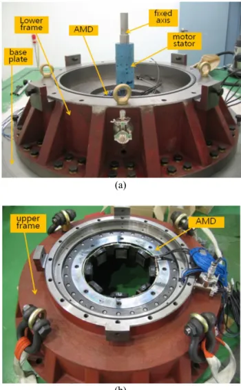
The main components of the 10 kWh FESS are assembled to respective housings, and the assembled housings are leveled and the central axes aligned for assembly to the main frame. The lower part of the main frame, shown in Fig. 10(a), is fixed to a base plate, and the lower radial AMD, lower thrust AMD and motor/generator stators are assembled to the frame.
The upper radial AMD and upper thrust AMD are assembled to the upper part of the main frame, shown in Fig. 10(b).
(a)
(b)
Fig. 10. 10 kWh class main frame (a)lower part and (b) upper part.
The composite flywheel, an assembly of the central open-core shaft, composite rotor assembly, radial and thrust AMD rotors, permanent magnet rotor, and
motor rotor, is inserted into the lower part assembly (Fig. 10(a)), as shown in Fig. 11.
Fig. 11. Composite flywheel being inserted to lower part assembly.
The upper part of the main frame from Fig. 10(b) is aligned over the lower part and flywheel assembly using guide bars, as shown in Fig. 12. The center axis of the upper part of the main frame is aligned with precision to the lower part of the main frame, to ensure stable operation of the system.
Fig. 12. Upper part of main frame being assembled to system.
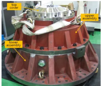
After all the power lines and sensors are connected, the top cover is assembled and the main frame is vacuum sealed(Fig. 13).
Fig. 13. Assembled 10 kWh class FESS.
IV. Conclusions
A 10 kWh class flywheel energy storage system was designed and constructed. Each major component of the system, including the composite flywheel, the radial and thrust active magnetic dampers, and the motor/generator were designed, simulated, built, and tested separately before being assembled to the system.
The 10 kWh class flywheel energy storage system is scheduled for test operation, and the results will be applied to the development of a 35 kWh class superconductor flywheel energy storage system.
Acknowledgments
This work was financially supported by Korea Energy Technology Evaluation and Planning.
References
[1] J. R. Hull, “Superconducting bearings”, Supercond.
Sci. Technol., vol. 13, p.R1 (2000).
[2] Nagaya, S. et al., “Study on high temperature superconducting magnetic bearings for 10 kWh flywheel energy storage system”, IEEE Trans. Applied Supercon., vol 11, pp. 1649-1652 (2001).
[3] Coombs, T. et al., “Superconducting magnetic bearings for energy storage flywheels”, IEEE Trans. Applied Supercon., vol. 9, pp. 968-971 (1999).
[4] Ichihara, T. et al., “Application of superconducting magnetic bearings to a 10 kWh-class flywheel energy storage system”, IEEE Trans. Applied Supercon., vol.
15, pp. 2245-2248 (2005).
[5] Lee, J. et al., “Vibration Control of Flywheel Energy Storage System”, Trans. of the Korean Inst. Of Elec.
Eng., vol. 58, pp. 1651-1833 (2009).