http://dx.doi.org/10.5369/JSST.2016.25.5.303 pISSN 1225-5475/eISSN 2093-7563
Illumination Control of LEDs in Visible Light Communication Using Manchester Code Transmission
Seong-Ho Lee
+Abstract
In this paper, we introduce a new method for controlling the illumination of LEDs in visible light communication (VLC) by changing the duty cycle of Manchester code. When VLC data were transmitted in Manchester code, the average optical power of the LEDs was proportional to the duty cycle. In experiments, we controlled the illumination of a 3 ×3 LED array from 10% to 90% of its peak value by changing the duty cycle of the Manchester code. The synchronizing clocks required for encoding and decoding the Manchester code were supplied by pulse generators that were connected to a 220 V power line. All pulse generators made the same pulses with a rep- etition frequency of 120 Hz, and they were synchronized with the full-wave rectified voltage of the power line. This scheme is a very simple and useful method for constructing indoor wireless sensor networks using LED light.
Keywords: LED, Visible light communication, Manchester code, Duty cycle, Illumination control
1. INTRODUCTION
Recently there have been great advances in semiconductor technology, and various types of high power light-emitting diodes (LEDs) have been developed. High power visible LEDs have become the most popular lighting sources, replacing conventional fluorescent lamps and incandescent lamps. LEDs have many advantages, including high efficiency, long lifetime, small size, and high speed modulation capabilities. Visible light communication (VLC) is one of the good application areas of LEDs, in which illumination and communication are carried out simultaneously with a single light source [1-4].
The LEDs used in VLC systems should always have stable and constant radiation whether data are transmitted or not because they are used for both illumination and communication simultaneously. In addition, it is desirable that the illumination of LED light be controllable without affecting the data transmission in VLC systems. In order to keep the average optical power of
LEDs constant for flicker-free illumination in VLC systems, data transmission methods using subcarrier modulation or pulse position modulation have been proposed [5-7].
We introduce another easy method to solve these two problems of LED light (flicker-free lighting and illumination control) by using Manchester code transmission in VLC systems. In Manchester codes, one data bit is replaced by “high-to-low” or
“low-to-high” transitions depending on the bit state. The “high” or
“low” state of LEDs corresponds to the instant that they are turned
“on” or “off”, respectively. The duty cycle is the fraction of the time that LEDs are in the “high” state compared to one bit time.
By changing the duty cycle of the Manchester code in VLC systems, the average optical power of LEDs was controlled.
Moreover, with a fixed duty cycle, the average optical power of the LEDs was kept constant without flickering.
2. MANCHESTER CODE GENERATION FROM ASCII CODE
Fig .1 shows an example of Manchester coding in a VLC system.
Fig. 1(a) is the ASCII waveform of the character “V” in a universal asynchronous receiver/transmitter (UART) format.
The ASCII code for the character “V” is “01010110”. When it is transmitted in UART format, the LSB (least significant bit) is sent first. Therefore, the transmitted bit sequence becomes
“01101010”. A start bit 0 is added in front of the character and the Department of Electronics & IT Media Engineering, Seoul National University
of Science and Technology, 232 Gongneung-ro, Nowon-gu, Seoul 139-743, Korea
+
Corresponding author: [email protected] (Received: Jul. 14, 2016, Accepted: Jul. 14, 2016)
This is an Open Access article distributed under the terms of the Creative Commons Attribution Non-Commercial License(http://creativecommons.org/
licenses/bync/3.0) which permits unrestricted non-commercial use, distribution,
and reproduction in any medium, provided the original work is properly cited.
resulting bit sequence becomes “001101010”. When high (H) voltage is assigned to “0”, and low (L) voltage to “1”, the voltage waveform for the character “V” is HHLLHLHLH, as shown in Fig. 1(a).
Fig. 1(b) denotes the sampling time to determine that the bit is in “high” or “low” state. The sampling time is set a little later than the start of each bit, and the sampling period is the same as one bit time. Fig. 1(c) is the Manchester code in which a “high” bit is changed to “high-to-low” and a “low” bit is changed to “low-to- high” in a bit time. If the duration of “high” is Δt and one bit time is T, the duty cycle is D= Δt/T. When the LED light is modulated by Manchester code, the average optical power is proportional to the duty cycle. If the duty cycle is fixed, the average power of the LED light is constant. If we change the duty cycle of the Manchester code, the average optical power is varied according to the duty cycle, that is, the illumination of the LED light is controlled.
In a VLC transmitter, ASCII code is changed to Manchester code, and in a VLC receiver the reverse operation is performed. A synchronizing clock is required in encoding and decoding of Manchester code. In our systems, the synchronizing clocks were supplied by pulse generators that were connected to the 220 V power line. Each pulse generator made synchronizing pulses with a repetition frequency of 120 Hz, which is double the power line frequency of 60 Hz.
3. SYSTEM CONFIGURATION 3.1 Experimental setup
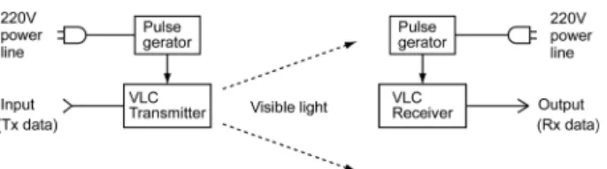
The overall system configuration for visible light communication with Manchester code is shown in Fig. 2.
A VLC transmitter modulated the LED light with input data and radiated the visible light into free space. A VLC receiver detected the signal light from the transmitter and recovered the transmitted data. Both the transmitter and the receiver were equipped with a pulse generator.
The three main components for Manchester code transmission were a pulse generator, a VLC transmitter, and a VLC receiver.
The schematic diagram and operation of these three components are now introduced one by one.
3.2 Pulse generator
A pulse generator makes clock pulses and supplies them to a VLC transmitter or receiver for synchronizing transmission. Fig. 3 is the schematic diagram of a pulse generator that was used in the experiments.
The pulse generator was composed of a transformer, a diode bridge, a comparator, and a microprocessor. The transformer dropped the 220 V AC voltage to 26 V AC, which was full-wave rectified by a diode bridge. A comparator made rectangular waveforms from full-wave rectified AC voltage, and a microprocessor generated short pulses at the falling edge of the comparator output. The output pulses had a repetition frequency Fig. 1. An example of Manchester coding.
Fig. 3. Pulse generator circuit.
of 120 Hz and they were used for synchronizing clock pulses in the VLC systems.
Each VLC transmitter and VLC receiver had its own pulse generator circuit, and encoded and decoded Manchester codes using the clock pulse as a reference time. Fig. 4 shows the pulse generator voltage waveforms observed using an oscilloscope.
Fig. 4(a) is the full wave rectified AC voltage observed at test point 1 (TP1) in Fig. 3. Fig. 4(b) is the comparator output voltage at TP2 in Fig. 3. Fig. 4(c) is the output pulse of the microprocessor at TP3 in Fig. 3. This pulse was used for synchronizing the VLC transmitters and VLC receivers. We set the pulse width to be 200 µs in experiments. The repetition frequency of the synchronizing pulse was 120 Hz.
Generally a 220 V power line is easily accessed in most rooms or offices, and so this scheme is a very convenient way of providing synchronizing pulses to all the VLC systems simultaneously. The pulse generator also had a voltage regulator circuit in order to provide DC power to all the devices within the VLC systems. Therefore, the pulse generators were used for two purposes; to get synchronizing pulses and DC power simultaneously.
The diodes used in the experiments were 1N4004, the comparator was an MC33272 op amp, the microprocessor was an Atmega8, and the voltage regulator was an MC7805.
3.3 VLC transmitter
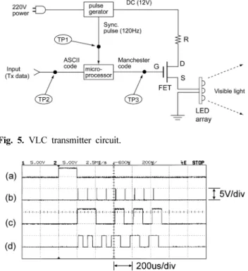
Fig. 5 shows the schematic diagram of the VLC transmitter.
The VLC transmitter was composed of an LED array, an FET, a microprocessor, and a pulse generator. The LED array was a visible light source for illumination and communication, and the FET was used for driving current to the LED array.
The microprocessor performed ASCII to Manchester code conversion with synchronizing clocks from the pulse generator.
The pulse generator was the same as that illustrated in Fig. 3.
Input data in ASCII code were applied to the input port of the microprocessor. The microprocessor changed the ASCII code to Manchester code with the clock pulse from the pulse generator.
The output signal of the microprocessor was applied to the gate of the FET, and DC bias voltage was supplied to the drain of the FET from the regulator in the pulse generator circuit. The source current of the FET was proportional to the gate voltage and flowed to an LED array. The LED array radiated visible light into free space.
Fig. 6 shows the VLC transmitter waveforms observed with an oscilloscope.
Fig. 6(a) is the synchronizing pulse from the pulse generator (TP1 in Fig. 5). The pulse width was 200 µs and the repetition frequency was 120 Hz. Fig. 6(b) denotes the sampling time in the microprocessor to determine that the input ASCII signal is “high”
or “low”. The sampling period was 100 µs, the same as one bit time. The sampling time was set to be 10 µs later than the beginning of the each bit time. Fig. 6(c) is the ASCII code of the character “V” that was applied to the input port of the microprocessor (TP2 in Fig. 5). This waveform was the same as that explained in Fig. 1 (a). It shows the ASCII code for the character “V” in UART format, and the bit sequence is
“HHLLHLHLH” as explained in Fig. 1 (a). Fig. 6(d) is the output voltage of the microprocessor which denotes the Manchester code Fig. 4. Signal waveforms in pulse generator. (a) Full wave rectified
AC voltage, (b) Comparator output voltage, and (c) Output
pulse for synchronizing. Fig. 5. VLC transmitter circuit.
Fig. 6. Signal waveforms in VLC transmitter. Synchronizing pulse,
(b) Sampling time, (c) ASCII code, and (d) Manchester code.
Optoelectronics Corporation. The resistor attached at the drain of the FET was 10Ω.
3.4 VLC receiver
Fig. 7 shows the configuration of the VLC receiver used in the experiments.
The VLC receiver was composed of a photodiode (PD), a load resistor (R
L), an amplifier, a microprocessor, and a pulse generator.
The photodiode received the visible light that was radiated from the VLC transmitter. The photocurrent flowed to the load resistor.
The voltage across the load resistor was amplified and applied to the input port of the microprocessor. The microprocessor changed the Manchester code to ASCII code with the clock pulse from the pulse generator. The pulse generator, which was the same as that shown in Fig. 3, supplied synchronizing clocks and DC power to the VLC receiver circuit.
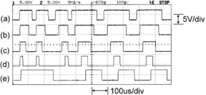
Fig. 8 shows the VLC receiver waveforms observed with an oscilloscope.
The sampling period was set to be 100 µs which was the same as one bit time.
Fig. 8 (c) is the received data in Manchester code (TP2 in Fig.
7). Fig. 8 (d) is the ASCII code recovered from the Manchester code (TP3 in Fig. 7). Comparing the transmitted ASCII data in Fig. 6 (c) and the recovered data in Fig. 8 (d), the two waveforms had the same shapes; however, there was a time delay of 20 µs in the recovered ASCII waveform. This is because we set the sampling times in the transmitter and in the receiver to be 10 µs later than the beginning of each bit time. Therefore total time delay of 20 µs existed between the transmitted and the received ASCII data.
The photodiode used in the experiments was a Hamamatsu PIN photodiode S6968, the load resistor was 10 kΩ, the amplifier was an MC33272 op-amp, and the microprocessor was an Atmega8.
4. ILLUMINATION CONTROL
4.1 Duty cycle change in a VLC transmitter
The brightness of the LED array was controlled by changing the duty cycle of the Manchester code. We observed the voltage waveforms in the VLC transmitter as we changed the duty cycle.
Fig. 9 shows the signal waveforms observed in the VLC transmitter using an oscilloscope.
Fig. 9 (a) is the ASCII code waveform of the character “V” in UART form. This is the same waveform as that in Fig. 6 (c) in a
Fig. 8. Signal waveforms in VLC receiver. (a) Synchronizing pulse, (b) Sampling time, (c) Manchester code, and (d) ASCII code.
Fig. 7. VLC receiver circuit.
Fig. 9. Signal waveforms in VLC transmitter. (a) ASCII code of a
transmitted character “V”, (b) Manchester code with a duty
cycle D=80%,(c) D=60%, (d) D=40%, and (e) D=20%.
different time scale of the oscilloscope. Figs. 9 (b), (c), (d), and (e) show the Manchester codes of the same character “V” with different duty cycles of 80%, 60%, 40%, and 20%, respectively.
These waveforms were observed at TP3 in Fig. 5. When the LED array in the VLC transmitter was modulated by these Manchester codes, the average optical power was proportional to the duty cycle. Therefore, the illumination of LED array was controlled linearly with the duty cycle. The optical power density from the LED array for each duty cycle was measured with an optical power meter in section 4.3.
4.2 Received waveforms in a VLC receiver
The VLC receiver was installed at a distance of about 1.5 meters from the VLC transmitter. In the VLC receiver, the photodiode received the light from the LED array and the microprocessor converted the Manchester code to ASCII code.
Fig. 10 shows the VLC receiver waveforms observed with an oscilloscope.
Figs. 10 (a), (b), (c), (d) are Manchester code waveforms observed in the VLC receiver with the duty cycle of 80%, 60%, 40%, and 20%, respectively. Fig. 10 (e) is the ASCII code waveform recovered from the Manchester codes. The recovered ASCII code waveforms were all the same for the Manchester codes with different duty cycles. Hence, the duty cycle change did not affect communication between the VLC transmitter and the receiver.
4.3 Illumination control by changing duty cycle The repetition frequency of the synchronizing pulses from the pulse generator was 120 Hz, which was double the power line frequency of 60 Hz. The pulse period (T
p) is the inverse of the repetition frequency (f
p), that is
(1) In experiments, we allocated seven characters to each pulse period, as shown in Fig. 11.
Fig. 11 (a) is the synchronizing pulse from the pulse generator (TP1 in Fig. 5). Fig. 11 (b) shows the ASCII codes of seven characters “\tVLC1\r\n” in sequence from left to right (TP2 in Fig.
5). Seven characters were transmitted between synchronizing pulses. In this case, we used 10 bits for one character, in which 8 bits were data and 2 bits were added for transmission. One of the two added bits was a start bit “high” which was the same as shown in Fig. 1. A stop bit “low” was added at the end of each character in order to create an interval between characters. Fig.
11(c) shows the Manchester codes for the seven characters. They were applied to the gate of the FET (TP3 in Fig. 5). The average optical power from the LED array is
(2)
where T
pis the period of synchronizing pulses, P(t) the is instantaneous optical power of the LED array, and N
cis the number of characters between synchronizing pulses. W
cis the optical energy in one character in Manchester code, and can be described as
(3)
where N
bis the number of bits in one character and Δt is the duration of the high state in Manchester code. P
1is the optical power of the LED array when it is in the high state continuously, D= Δt/T
bitis the duty cycle, and T
bitis one bit time. Substituting (3) in (2), the average optical power of the LED array is
(4) T
p= 1 f ⁄
p= 1 120 8.3 ms ⁄ ≅ ( )
P
avg1 T
p--- P t ( ) t d
t 0= Tp