Introduction
The search for more detailed understanding about lesions of human body is an unending process. These endeavors are without excep- tion in dental implant dentistry. For an in- stance, several parameter have been described to determine conditions of peri-implant. One of these parameter is the observation of changes in peri-implant bone levels. Since major changes take place in alveolar bone during progression of peri-implant disease and heal- ing following implant therapy result in alveo- lar bone changes, this parameter is important in patients with implant prostheses as a means of precaution. Diagnoses, however, are often restricted to the assessment of implant mobility, clinical periodontal parameters(Gingival Index, Plaque Index, pocket depth, etc.), and conventional radiographic evaluation.
As focus radiography, the intraoral radi- ographic images have been the primary di- agnostic method not only for the assessment of bone support, as well as but also for the detection and measurement of bone change.
Although conventional radiographic techniques is one of the most frequently applied and non-
invasive diagnostic procedures, they have shown their limitations considerably up to the present. Early stages of bone disease cannot be detected by means of routine ra- diographs, nor can the size of a rarefied area on the radiograph be correlated with the amount of tissue destruction1). And, it is not uncommon to find clinical signs of bone dis- ease in spite of negative radiographic findings.
Thus, it seems that the reasons are fore- shortening or elongation of the radiographic images, variations in the contrast and densi- ty of radiograph, and difficulty in detecting bone change lies in the two-dimensional na- ture of the conventional radiograph2).
For these reasons many radiographic meth- ods3-9) have been developed to improve accu- racy in detecting changes in alveolar bone and osseous tissues bone conditions adjacent to im- plant. During the latest few years, reliable methods for obtaining superimposable radi- ographic images3,4) of periodontal sites have been developed. This method can provide precise information about bone quality without misinterpretations of bone density due to angular variation of radiology. Although long- term longitudinal study have been done, there
대한치과보철학회지:Vol. 36, No. 6, 1998
Evaluation of bone quality in alveolar crest obscured by dental implants ; A pilot study by densitometric digital
analysis in mandibular bone specimen
Kung-Rock Kwon, D.D.S., M.S.D., Ph.D
Department of Prosthodontics, College of Dentistry, KyungHee University
were no addressed buccal and lingual sides of bone quality, behind the implant except for restricted spaces between implants and osseous tissue suround the implant.
Despite the computerized method provided to be efficient and accurate for comparing bone changes adjacent to dental implants as ob- tained from standardized longitudinal radi- ographs, it also presented restricted area of bone changes, the changes detected in prox- imal area only. Bone conditions in behind of implant (buccal or lingual), however, and could not be detected, unless their mass was huge10). This was probably due to the high ra- diographic density of the implant, and the condition of buccal and lingual of the implant became saturated on the radiographic images consequently.
More recently, photodensitometry and digi- tization4,11) have been used for the sensitive an- alytical technique to detect subtle changes of bone density. Photodensitometric technique is known to provide high spatial resolution and continuous measurement of optical density for analysis of dental radiographs, whereas dig- itization allows powerful image manipulations.
Concept of our technique used this study is closer to the computer-assisted densitometric image analysis(CADIA)’ rather than the classical quantitative subtraction.
For the evaluation of long-term success rates for dental implants, several criteria have been used. Although the computerized method provided to be efficient and accurate for comparing bone changes adjacent to dental implants as obtained from standardized longi- tudinal radiographs, it also presented restrict- ed area of bone changes. Bone all surrounding osseous tissues of implant should be evaluat- ed. Initial bone change started at the buccal area after implant insertion, however only interproximal bone change could be mea-
sured on radiographs as yet. Conditions of be- hind of implant are more important point to evaluation of success or fail of implant, how- ever, those bone changes have not been ad- dressed as yet.
Owing to such reasons, this study was planned (1) to find out the detective method obscured of bone destruction by dental im- plants through the series of superimposable in- traoral radiograph, destructions adjacent to ITI� implants(especially buccal and lingual sides), (2) to propose a simplified procedure to assess those bone changes, what specific ra- diographic technique was easily detectable by usual intraoral radiographs, and (3) to ver- ify of the reliability using this computerized high resolution densitometric technique.
Material and Methods Mandiblular bone sample
A specimen from postmortem human mandible with complete edentulism was used for this bone density analysis. The dry mandibular bone was obtained from corpse subjected to educational dissection at the Department of Anatomy, University of Geneva, Switzerland. No data with regard to sample’s characteristics except for bone qual- ity (class IV ;according to classification of Lekholm and Zarb12)) was available.
Implant insertion and bone section
Implant sites were prepared in the mandibu- lar bone according to the surgical sequence.
The basal compact bone was always perfo- rated with the intention of further use.
The 10 ITI� (Institute Straumann, Waldenburg, Switzerland) solid screw im- plants (3.3mm in diameter, 8mm in length)
without healing cap were inserted in the edentulous mandibular bone: Six(6) in the posterior region and four(4) in the anterior re- gion.
After insertion of implants, the mandibular bone was cut to make 10 sectioned bone specimens with implant respectively.
Superimposable radiography
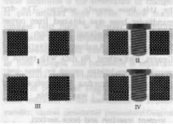
The experimental protocol was planned to compare the conventional periapical projections and the oblique occlusal projections. For this purpose, superimposable serial radiographs were taken four(4) simulated clinical situations for each sectioned bone(Fig. 1) ; making hall for implant(stage I), insertion of the implant into the bone(stage II), making bone defects on buccal or lingual side adjacent to the im- plant(stage III), removal the implant from the hall(stage IV). Half-rounded artificial defects were made by No.208 round low speed steel bur with 2mm diameter(Mailleffr SA,
Switzerland). In each situation, two projections of perpendicular to the long axis of implant, that is, bucco-lingual(BL) and misio-dis- tal(MD) projections as like conventional peri- apical views, and another two angled(25 de- grees) projections to the long axis of implant, that is, oblique BL and oblique MD projections as like oblique occlusal views were used, re- spectively(Fig. 2). The shoulder of 3.3mm-di- ameter implant used this study is flared about 21 degrees. This angle is the most se- vere within commercially produced ITI� im- plants. Of course, the angle of projection will be able to change dependent on shape of im- plant shoulder.
In order to keep the same position and ac- curate(90 degrees) turn of the sectioned specimen, a thread cutter(044.511, Institute Straumann, Switzerland) was used. This in- strument was inserted into the basal bone of mandible with paralleling to axis of implant.
After combination with a ratchet(0.46.183, Institute Straumann, Switzerland), it was po-
Fig. 1. Experimental x-ray taking protocol;
I. making hall for implant(stage I), II.
Insertion the implant into bone(stage II), III. making the bone defects on buccal and lingual adjacent to the implant(stage III), IV. removal the implant from the hall(stage IV).
Fig. 2. Projection of x-ray beam BL=bucco-lingual projection, MD=mesio-distal projection,
OBL=oblique-bucco-lingual projection, OMD=oblique-mesio-distal projection
sitioned on the table to take the radiograph.
The specimen has been turned just 90 degrees for each projection, instead of turning the long cone x-ray tube. Total 16 radiographs(4 sit- uations X 4 projections) were taken for each specimen.
Reproducible radiographs were achieved by using this standardized tool which contained an aluminum alloy penetrometer. The long cone x-ray tube (Heliodent MD, Siemens AG, Germany), and a custom-fabricated parallel- ing device by Graf et al13) are shown in Fig. 3. The paralleling device is made of in- jected plastic and includes within the same rigid structure a film holder, a penetrometer holder made from two parallel pins, arm for connection to the cone and two supports to maintain same angulation of beam without bite try which is usually used in clinical sit- uation. A specially designed metal collar is adapted to the x-ray cone, and a rail permits
connection of the rigid T’ sectioned plastic arm to the cone in a constant position by us- ing a metallic pin and screw. The source to film distance provided by long cone and film holder was approximately 41cm in this study.
All radiographs were taken with D-speed film(Ultra-speed�, Kodak, USA) with fol- lowing exposure parameters : 0.16 second, 15mA, 75kV. We affirmed that exposure time of 0.16 second is more detail to contrast by previous test. They were processed with constant developing and fixing times.
Preparation of the films: To achieve the best possible placement during the digital analysis, three reference points were added in the beside of bone specimen over the film, as extend as possible. Three tiny holes were punched with a thin needle under a stere- omicroscope on the first film. The second film of the series was superimposed on the first under a stereomicroscope, using the outlines of the thread cutter as a reference; the same reference points as on the first radiograph were then punched out. The same procedure was applied to the two other films of the se- ries.
High-resolution digital analysis: The tech- nique used for quantifying the density of bone was based on a high resolution digitiza- tion of the radiographic films and implies the use of a video camera(Kodak-EikonixTM, USA) with a maximum resolution of 4096 X 4096 pixels and up to 4096 gray levels(12 bits acquisition). The radiographs were digitized at about 1200 X 1600 pixels and all the available gray levels utilized. The camera was driven by a SUN SPARC(Sun Microsystem Inc., Mountain View, California, USA) and a spe- cific software(LaboImage, Computing Science Center, Geneva University) was then used to Fig. 3. The paralleling device used this
study(Adapted from B.Dubrez et. al17,) schematic representation of paralleling device in mouth and of metal collar(c) with its four rails(b) on theb) on the he x-ray tube. The plastic arm(d) can be fixed to one of the four rails through a screw(a) and a pin(e) for the orifice in the plastic arm(e)
analyze the stored images. Successive images of a series of radiographs were placed by LaboImage in identical positions with the help of precise dots punched on the films un- der microscophic control. Then, LaboImage in scanned the penetrometer area between iden- tical points and was able to convert the
gray levels of the original pixels into values corresponding to aluminum equivalents. This conversion was obtained for each radiograph by approximating a theoretical curve by a third degree polynomial fit of the constant part of the penetrometer. Several scans of inter- esting area were read an each of the four(4) Fig. 4. Scans of interesting areas :
1) bucco-lingual (BL) projection-an horizontal scan across the crestal bone defect(R2), cre- stal bone defect obscured by implant(R1), and no crestal bone defect area(R3) ; 2) mesio- distal(MD) projection-an horizontal scan across the crestal bone defect(R2) and crestal bone defect obscured by implant(R1); 2nd horizontal scan in much deep area, where no bone changes were to be expected( R3-1and R3-2) ; 3) oblique-mesio-distal(OMD) projection- an horizontal scan across the crestal bone defect(R2), crestal bone defect obscured by im- plant(R1), and no crestal bone defect area(R3) ; a vertical scan along the lateral contour of implant(R0) ; 4) oblique-bucco-lingual(OBL) projection-an horizontal scan across the crestal bone defect(R2), crestal bone defect obscured by implant(R1), and no crestal bone defect area(R3) ; a vertical scan along the lateral contour of implant(R0)
series radiographs(Fig. 4).
Direct pixel by pixel comparison between the images was thus possible and any area could be analyzed by LaboImage in scanning mode.
The curves provided by each series of scans were visualized graphically. Surfaces located under each successive curve were calculated by mathematical integration. Finally, the val- ue of the surface under the stage I curve was set to 100 and each change expressed as per- centage of this stage I surface.
Due to technical problems during sample handling, nine(9) specimens became available for subsequent densitometric digital analysis.
Statistical analysis
The changes of bone density in mandibular specimen were investigated after artificial defects in buccal and proximal sides adjacent to the dental implants. ANOVA, followed by Neuman-Keuls method was performed to
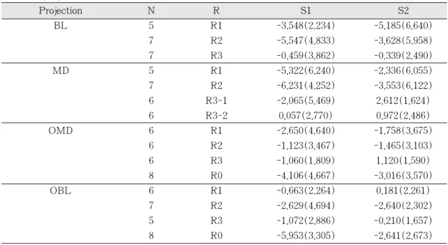
Table 1. Average of change of bone density (%) in mandibular skull after defect by 4 series of projection
Projection N R S1 S2
BL 5 R1 -3.548(2.234) -5.185(6.640)
7 R2 -5.547(4.833) -3.628(5.958)
7 R3 -0.459(3.862) -0.339(2.490)
MD 5 R1 -5.322(6.240) -2.336(6.055)
7 R2 -6.231(4.252) -3.553(6.122)
6 R3-1 -2.065(5.469) 2.612(1.624)
6 R3-2 0.057(2.770) 0.972(2.486)
OMD 6 R1 -2.650(4.640) -1.758(3.675)
6 R2 -1.123(3.467) -1.465(3.103)
6 R3 -1.060(1.809) 1.120(1.590)
8 R0 -4.106(4.667) -3.016(3.570)
OBL 6 R1 -0.663(2.264) 0.181(2.261)
7 R2 -2.629(4.694) -2.640(2.302)
5 R3 -1.072(2.886) -0.210(1.657)
8 R0 -5.953(3.305) -2.641(2.673)
BL=bucco-lingual projection, MD=mesio-distal projection, OMD=(reverse) oblique mesio-distal projection,
OBL=(reverse) oblique bucco-lingual projection,
N=number of sample, R=interesting region (R0=unscreened defect which was analyzed by oblique direction, R1=screened defect with implant, R2=unscreened defect which was analyzed by hor- izontal direction, R3=no defect, R3-1=no defect in deep surface & screened with implant, R3- 2=no defect in deep surface & unscreened with implant), S1=bone density change of defect with- out implant, S2=bone density change of defect with implant,
Numbers in parentheses are standard deviations.
‘+’=bone gain, ‘-‘=bone loss
compare the statistically significant differ- ence of the bone density obtained by each projection of radiography. T tests, F tests, and Mann-Whitney W tests were used to compare means, and standard deviations and medians, respectively.
All analyses were performed significant confidence level at 0.05.
Results
In total nine(9) implants, 144 superimposable radiographs were analyzed. Due to the discord position of radiographs, some series of them were not available for analysis. If one radi- ograph was not superimposed, then the whole series of four(4) radiographs (from stage I to stage IV) was not used.
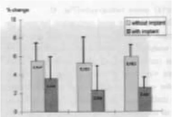
Average of change of bone density in mandibular specimen after defect by all series of projection are shown in Table 1. In Fig. 5 buccal bone defect and Fig. 6 proximal bone defect are shown.
The average density change of buccal bone defect was 3.548% in BL projection and 4.106% in OMD projection with obscured by implant. In case of proximal bone defect was 5.953% in OBL projection, followed by 5.547%
in BL projection, 5.322% in MD projection.
However, in both of cases, the differences be- tween projections of x-ray beam were not sta- tistically significant in ANOVA results.
The diagnostic accuracy between defect(su- perficial portion) area and non defect(deep portion) area in same projection(MD) was sta- tistically significant difference(p<0.05) as fol- lows:The R3-2 has lower mean(0.057%) and median (-0.285%) of bone density change than those of R2(mean=-6.230%, median=
-6.07%) in S1, respectively. The R3-2 has lower standard deviation of mean(2.486%) bone density change than that of R2(6.122%) in S2. The R3-1 has lower mean(2.612%), median(2.370%) of bone density change and standard deviation(1.624%) than those of R1(mean=-2.336%, median=-0.180%, stan- Fig. 5. Change of bone density(%) on buccal
defect
MD=mesio-distal projection, BL=bucco-lingual projection,
OMD=oblique-mesio-distal projection.
The vertical bar is standard error of mean.
Fig. 6. Change of bone density(%) on prox- imal defect
BL=bucco-lingual projection, MD=mesio-distal projection,
OBL=oblique-bucco-lingual projection.
The vertical bar is standard error of mean.
dard deviation=6.055%) in S2, respectively.
The diagnostic accuracy between projections of x-ray beam was shown as comparing R3 in BL, R3 in OMD, and R3 in OBL projec- tion. R3 in BL has lower bone density change(0.459 3.862%) than those of others (1.060 1.809% in OMD, 1.072 2.886% in OBL). However, no statistically significant difference was shown.
Discussion Backgrounds of concepts
Tomogram has been used with good success for the assess of implant site in pre-and post treatment. However, it is limited to use by special circumstances due to the high cost of the equipment and the availability of a trained radiologist to obtain and interpret the image14). In implant practice, the panoramic image and periapical radiograph commonly used to the detection of change at the adja- cent to implant. Periapical radiograph to assess marginal bone level around implants has been prepared due to the increased detail obtained with intraoral film as compared with panoram- ic radiograph. Periapical radiograph may have limited efficacy for evaluation of bone change in area of obscured by dental implants. This is the most critical factor whenever used for detection the circumferential bone quality by intraoral film.
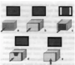
In dental radiography15), images portray the trabeculae of cancellous bone as looking like a kind of lattice(Fig. 7a). And , the cancellous bone is invariably enclosed by dense compact bone which contributes to cumulative record of beam attenuation whenever it overlies the tra- becular bone(Fig. 7b). If the compact bone is relatively low thickness by comparison with the cancellous bone, discernible image feature
leave(Fig. 7c). This circumstance is exempli- fied by absence of any image of the compact bone comparing buccal and lingual aspects(Fig.
7d), another image through the cancellous bone between bottom plate of cortical bone and crest of cortical bone which is low thick- ness of absence due to destructive disease as in mandible(Fig. 7e). Occlusal projection in- stead of lateral projection may offer the so- lution of above problem, if the x-ray beam and long axis of the implant are properly aligned.
Fig. 7. Radiographic images ;
a) image through block of cancellous or trabecular bone. b) image through block of cancellous bone between two outer plates of cortical bone. Image is lighter than that of unmasked tra- becular bone. c) image through block of cancellous bone at edges of which are slabs of compact bone to be pen- etrated in depth. d) image through simulated bony defect. e) image through one plate of cortical bone of bottom. Image is lighter than that of unmasked trabecular bone, and dark- er than that of masked trabecular bone by two cortical plates.
On the basis of above grounds, this study was focused the utility of quantitative radi- ography taken by intraoral films in detecting bone change obscured by dental implants.
For this purpose, oblique(25 degrees) occlusal x-ray projections and conventional periapical projections were used and compared.
Considerations of experimental methods
Quantitative radiography is noninvasive method to assess alveolar bone changes, how- ever it has been shown potentiality to make misinterpretations caused by projection er-
rors16,17). From this references, three landmark
points were made after developing the films to provide the repositioning accuracy in this study. The coordinates of three landmarks can offer the prerequisites for the application of the simplified mathematics formulas and rapid evaluation of the superimposability of serial ra- diographs.
The system described in here represents a modification of the method used by Dubrez et.
al4,11,18). The only different thing is the instru- ments-the thread cutter and ratchet-were used instead of silicone bite block as used oth- er in vivo studies. The instruments made a precise role to allow rotate just 90 degrees of sample in each certain position. The parallel- ing device, the long cone of the x-ray unit holding film and penetrometer was fixed a same position, Then, the rotate of 25 and 90 degrees to long axis of implant was performed to take all series of radiograph.
On the results of this study performed on a dried mandible, the greater change of bone density in defect area made by low speed dental bur(half depth of 2mm diameter) was shown by BL projection, even in area obscured by the implant. When comparing defected and non-defected area, more than 3% of bone
density change has shown in defected area.
Generally, there was 1 or 2% of bone densi- ty change in other clinical follow-up studies4,18). The defect sizes obscured by them were mostly bigger than the defect used in this study. It might be expected that this in vit- ro study using the dried skull without skin would lead to the greater sensitivity. And, the bone quality was class IV, which were thin cortical bone surrounds loose, spongy core.
Hence, it was perhaps the reason why this re- sult has shown more sensitivity rather than other in vivo studies11,19).
Radiographic results
Reproducibility : The reproducibility of this method has been about 1% of variation11,17). However, non-defected area as a control group, where no bony changes to be expect- ed, has shown more than 3% of variation in this study. This variation imply that an at- tempt to standardize the series of radiographic image is not so easy.
The experimental bone defects were pro- duced using a dental round bur with 2mm di- ameter. The defects were located in buccal and proximal to simulate decreased bone density of alveolar bone in the region of in- terest. The size of defect was standardized as half depth of diameter. Nevertheless, false neg- ative or positive results were found for the de- tection of the some samples. The R3-1 in S2 of MD projection is an example of false neg- ative result. One possible explanation is that when the radiographs were analyzed, some other factors such as implant body might be involved. Of course, this problem was due to non-superimposed radiographs.
Otherwise, the R3-1 in S2 of MD projection is an example of false positive result. This sit- uation was neither defect nor obscured by im-
plant in deep portion. Hence, an explanation could be that the false positive results were caused by lose of bone chips during the re- moval of implant according to experimental protocol. Some of bone particles on the TPS(titanium plasma sprayed) surface of implant were observed whenever removal of implants from the bone samples. Therefore, the density of bone would be relatively decreased.
Another reason, may account for the false positive results, seems that some parts of bone chips were perhaps broken down during the removal of implant. Although, small change of bone particles, it can be detected since the high sensitivity of this system.
These might become distinct due to dry condition of the bone.
Although same digitizing analysis has been used in previous another studies4,11,18), the de- fect behind obscuring factor could not be detected yet in clinical field. Within results of this study, both of the oblique projection like occlusal radiographs and conventional periapi- cal projection appeared reasonably sensitive in detecting bone density changes obscured by dental implant. In this in vitro study, no heal- ing caps or abutments were placed on the im- plant. For ITI� dental implant, furthermore, the thickness of neck area is relatively shal- low than other part of implant in mechanical geometric. These lack of radiopaque compo- nents would allow for possibility to detect the subtle changes behind the implant. This as- sumption is in accordance with data by Formousis et. al10). They reported bone chips in buccal defect(behind the implant) of pig mandible, however, detected using by com- puter-assisted densitometric image analy- sis(CADIA), if their weight reached 14mg or more. It means that the digitizing analysis sys- tem could detect bone changes dependent on relative density against obscuring effect, while
the conventional radiographs could not detect them.
Reliability: When comparing the bone den- sity between before and after defect in situ- ation with implant, the significant difference of median was shown in non-obscured bone defect by implant in BL and OBL projections.
Otherwise, no significant difference was ob- served in obscured bone defect by the implant, even if great bone density changes have shown as in Table 1. It is supposed that the great standard deviation would lead to these statistical results by paired sample tests. On the other hand, a somewhat difference of mean was interestingly observed in obscured bone defect by implant in OMD projec- tion(p=0.09). This result did not show the statistically significant difference of bone den- sity change as comparison before and after bone defect. Nevertheless, this seems to be a reliable method for detect subtle bone densi- ty change.
As concerns reliability of the result in situ- ation with implant(S2), the bone density change of non-defect area appeared 2.612% in MD projection, despite it should be 0% dif- ference in theoretical. It is assumed that this projection would give a reliable baseline data of diagnostic error because there was only spongy cores. The each mean of bone den- sity change in non defected area(R3) was as- sumed as each diagnostic error. On basis of the results, the bone density changes have shown 5.185% in behind implant, 3.628% in unscreened area by BL projection. It was about 1% greater than the amount of diag- nostic error which was assumed as 2.612% in this circumstance. The similar finding was al- so observed in situation without implant(S1).
Such an evaluation made with low-contrast would be less accurate and subjected to more
variation, however, it could provide important information for clinician to make a diagnosis of implant patient. Furthermore, the abutments could be removed for radiographic evaluation, this digitizing radiographic diagnostic system could overcome the absorb of x-rays resulting in obscuring area, whenever use conventional periapical radiographs.
Conventional periapical projections versus oblique occlusal projections: Although no sta- tistically significant difference was observed, the conventional periapical projections ap- peared more sensitivity than oblique occlusal projections as compared with two different projections of x-ray beam. In case of buccal defect obscured by implant(It is our interest- ing topic), OMD projection has shown 3.016%
of density change while BL projection has shown 5.185%. In this study, the influence of the absence of titanium healing cap would lead to the remarkable sensitivity of BL pro- jection(conventional periapical view). However, it was supposed that the sensitivity of con- ventional periapical view would be still ques- tionable or low. In addition, the sensitivity will be depended on relative radiopacity of objects.
On the other hand, the oblique occlusal pro- jections were always available for viewing re- gardless of obscuring effect. Some paired im- ages were found unsuitable for quantitative analysis. This frequency in oblique occlusal projection was more or less higher than in conventional periapical projection. It seems that the changes in specimen position would result in altered x-ray beam projection. Due to the inaccuracy of superimposable radiograph, bone loss may not be localized, and the po- tential obscuring effect of x-ray beam angu- lation may greater affect this result. If the an- gulation of x-ray beam, or superimposition of radiographs were not constant through 4 se- ries of radiographs, interesting area adjacent
to implant was difficult to be chosen without obscuring effect by radiopacity of implant.
May be, it was the reason why the error of diagnosis in oblique occlusal projections(1.120%) were more greater than conventional periapi- cal projections(0.339%).
Hausmann et. al20) reported effect of x-ray beam vertical angulation on radiographic alve- olar crestal level and noted that the beam angle variation resulted in bone score differ- ences. This problem could be solved using a device to offer the constant relationship be- tween the x-ray tube, alveolar bone, and film when application in clinical practice. As a prerequisite for digital analysis method, stan- dardized radiographs must be obtained with great accuracy21). When comparing between non-obscured by implants(S1) and obscured condition(S2), the latter has shown about 1.6% greater bone density changes than that of the former in the same specimens. For in- stance, in buccal defect obscured by im- plant(R1) in BL projection, a -5.185% of bone density change was observed in S2, while -3.548% was shown in S1. Logically, the two conditions should have equal density, if there was no other factors which is expected to produce the bone change. One possible ex- planation is that the experimental protocol would affect the different results. According to protocol-drilling(stage I), place the im- plant(stage II), making defect adjacent to im- plant(stage III), and removal of implant(stage IV)-bone chips would be, more or less, lose during stage I and stage IV when removal of implant, while no change of bone chips would be expected during stage II and stage III.
Nevertheless, all of the changes seen here were quite enough greater to accept the re- sults when compared with those of their non-defected control areas which was -0.459%
in S1 and -0.339% in S2.
As concerns analyzing method, despite no statistically significant difference was ob- served(p=0.09 in OMD, p=0.07 in OBL pro- jection), the results performed by vertical direction had higher sensitivity than by hor- izontal direction. The former was also more easily and simply used for analyzing the film of oblique occlusal projection during scan- ning procedure.
Despite of more sophisticated method, the standardization of all procedures involved in producing identical radiographs remains the disadvantage factor that may not be suffi- ciently reproducible in clinical trials yet. The most important factors for making a proper radiographs are the quality of the equipment including its software together with the op- erator or examiner’s experience. Another critical factor is that the oblique occlusal projection would be limited by presence of prostheses, furthermore in case of maxillary bone loss.
Additional study on oblique occlusal projec- tion is needed to investigate the significance of this method not only in taking the radi- ograph but also in analyzing methods.
Summary
Despite of technical difficulties, the combi- nation of occlusal projection and densitometric digital analysis may ultimately provide a means of detection of subtle bone loss at the facial and lingual side of dental implant (Oblique occlusal view is more useful for ITI� dental implant due to its contour of shoulder as like tulip’flower). In this study, conventional periapical projections of x-ray beam had shown more high sensitivity to de- tect the bony defects than oblique occlusal projections in alveolar crest obscured by den- tal implants or not, even if the difference was
not statistically significant. Unlike conven- tional periapical projections, occusal projec- tions combined with densitometric digital analysis technique may provide a means for detection of subtle bone change at the all around of implants without obscuring effect by implant itself.
Although the results from this in vitro study were performed under limited circumstances, these results might afford more possibility and versatile modality of diagnosis options to clinician in the implant practice.
Acknowledgements
I wish to thank Dr. Patrick Brochut (Geneva University, Switzerland) for the analysis of radiographs, and also thank to Mr.
Vincenzo Grande (Institute Straumann, Waldenburg, Switzerland) for providing the ITI� implants.
References
1. Bender IB, Seltzer S. Roentgenographic and direct observation of experimental le- sions in bone : II. JADA 1961;62:708-716.
2. Jeffcoat MK. Radiographic methods for the detection of progressive alveolar bone loss. J Periodontol 1992;63:367-372.
3. Payot P, Haroutunian B, Pochon Y, Herr P, Bickel M, Cimasoni G. Densitometric analysis of lower molar interradicular areas in superposable radiographs. J Clin Periodontol 1987;14:1-7.
4. Dubrez B, Duroux P, Cimasoni G. Bone density of class II furcation lesions treated by guided tissue regeneration: A follow-up study by digital analysis of superimposable radiographs. J Clin Periodontol 1996;23:882- 888.
5. Bragger U. Digital imaging in periodontal
radiography. J Clin Periodontol 1988;15:551- 557.
6. Bragger U, Pasquali L, Kornman KS.
Remodelling of interdental alveolar bone af- ter periodontal flap procedures assessed by means of computer-assisted densito- metric image analysis(CADIA). J Clin Periodontol 1988;15:558-564.
7. Hausmann E, McHenry K, Christersson B, Rosling B, Ortman LF. Techniques for assessing alveolarbone mass changes in periodontal disease with emphasis on 125I absorptiometry. J Clin Periodontol 1983;10:455-464.
8. Bragger U. Radiographic parameters for the evaluation of peri-implant tissues.
Periodontology 2000 1994;4:87-97.
9. Hausmann E. A contemporary perspective on techniques for the clinical assessment of alveolar bone. J Periodontol 1990;61:149- 156.
10. Fourmousis I, Bragger U, Burgin W, Tonetti M, Lang NP. Digital image pro- cessing : II. in vitro quantitative evaluation of soft and hard peri-implant tissue. Clin Oral Impl Res 1994;5:105-114.
11. Dubrez B, Jacot-Descombes A, Pun T, Cimasoni G. Comparison of photodensito- metric with high-resolution digital analysis of bone density from serial dental radi- ographs. Dentomaxillofac Radiol 1992;21:40- 44.
12. Lekholm U, Zarb GA. Patient selection and preparation. In : Branemark PI, Zarb GA, Albreksson T, ed. Tissue-integrated pros- theses: osseointegration in clinical den- tistry, Quintessence Pub. Co., 1985, pp 199-209.
13. Graf JM, Mounir A, Payot P, Cimasoni G.
A simple paralleling instrument for
superimposing radiographs of the molar regions. Oral Surg Oral Med Oral Pathol 1988;66:502-506.
14. Miles DA, Van Dis ML. Implant radiology.
Dent Clin North Am 1993;37:645-668.
15. Barr JH, Stephen RG. Radiographic infor- mation. In : Dental radiology : pertinent basic concepts and their applications in clinical practice, WB Saunders, 1980, pp 203-209.
16. Hausmann E, Allen KM, Piedmonte MR.
Influence of variations in projection geometry and lesion size on detection of computer-simulated crestal alveolar bone lesions by subtraction radiography. J Periodont Res 1991;26:48-51.
17. Dubrez B, Jacot-Descombes S, Cimasoni G.
Reliability of a paralleling instrument for dental radiographs. Oral Surg Oral Med Oral Pathol 1995;80:358-364.
18. Brochut PF. Regeneration tissulaire guidee avec ou sans greffe osseuse evaluation clinique et densitometrique (Thesis in Geneva univ.), 1997. in French
19. Ortman LF, Dunford R, McHenry K, Hausmann E. Subtraction radiography and computer assisted densitometric analyses of standardized radiographs: a comparison study with 125I absorptiometry. J Periodont Res 1985;20:644-651.
20. Hausmann E, Allen K, Christersson L, Genco RJ. Effect of x-ray beam vertical angulation on radiographic alveolar crest level measurement. J Periodont Res 1980;24:8-19.
21. Grondahl K, Grondahl HG, Webber RL.
Influence of variation in projection geome- try on the detectability of periodontal bone lesions. J clin Periodontol 1984;11:411- 420.
임플란트 치과 임상에서, 협, 설측의 골조직 상태는 임플란트 재료의 높은 밀도 때문에 구내용 방사선사진으로는 파악할 수 없으나, 디지털 분석을 이용한 정량적 방사선 분석법을 사용하여 이 부위를 파악하고자 하였다.
건조 하악골에 10개의 직경 3.3mm인 solid screw형태의 ITI� 임플란트(Institute Straumann, Waldenberg, Switzerland)을 매식한 다음, 이들을 10개의 골 시편으로 절단한 후, 방사선사진 촬영 을 시행했다. 일련의 중첩상을 얻기 위해, 특별히 고안된 방사선필름 고정기와 D속도 필름(Ultra- speed�, Kodak, USA)을 사용했으며, 고 해상도의 디지털 분석을 위해, 비디오카메라(Kodak-Eikonix
™, USA)로 필름을 scan하고 software(LaboImage, Computing Science Center, Geneva University)를 이용해 정량적 분석을 시행했다.
방사선 촬영은 4 방향(통상적인 periapical projection에 의한 근, 원심(MD)방향 및 협, 설(BL) 조 사위, 통상적인 occlusal projection에 준한 25도 경사진 근, 원심(OMD) 및 25도 경사진 협, 설(OBL) 조사위)으로 시행했으며, 각 시편에서 4장의 연속 중첩 방사선사진(superimposable radiograph)을 임 플란트 매식공 천공 후, 임플란트 매식 후, 임플란트 주변(협,설) 골 손상 후, 임플란트 제거 후의 상황에서 표준화된 방법으로 촬영해서 얻었다.
기술적인 어려움에도 불구하고, occlusal projection으로 촬영하고, 이를 디지털 농도 분석한 방법 에서, 치과 임플란트 주변 협, 설측의 미세골 변화를 파악할 수 있을 것으로 보였다. 특히, occlusal projection이 periapical projection에 비해 더욱 민감한 골 변화를 인지하는 것으로 나타났다. 비록 이 실험의 결과가 제한된 조건에서 얻어졌지만, 실제 임플란트 임상에서 임상가들에게 진단적 차원 에서의 새로운 가능성과 다양성을 제시해 줄 수 있으리라 사료된다.
중심어 : 디지털 밀도 분석, 골밀도, 중첩 방사선사진, 임플란트
치과 임플란트 주변 협설측 치조골의 변화분석
- 하악골 시편에서의 디지털 농도분석법을 이용한 실험적 고찰 -
경희대학교 치과대학 보철학교실 권 긍 록
국문초록