I. Introduction
Bio-impedance is expected to provide a wide range of useful information related to heterogeneous tissue structures, and physiological states and functions [1]. Several authors have used impedance spectroscopy in their study of the electrical properties of skin [2-4]. Skin impedance can be investigated using different conditions and methods. It is inexpensive, not harmful to patients, and convenient for image monitor- ing. This is determined in subjects by the ratio of the voltage to the current.
Electrical impedance tomography has been used for imag- ing of both geometry and skin impedance (conductivity) distribution in internal tissues through non-invasive mea- surement of skin impedance on the body surface [5-7].
This research employs an electrical impedance model,
A New Method for Non-Invasive Measurement of Skin in the Low Frequency Range
Min Soo Kim, PhD1, Youngchang Cho, PhD2, Suk-Tae Seo, PhD1, Chang-Sik Son, PhD3, Hee-Joon Park, PhD4, Yoon-Nyun Kim, MD, PhD5
1Biomedical Information Technology Center, Keimyung University, Daegu; 2Department of Information and Communication, Kyungwoon University, Kumi;
3Department of Medical Informatics, School of Medicine, Keimyung University; 4Department of Biomedical Engineering, School of Medicine, Keimyung University; 5Department of Internal Medicine, School of Medicine, Keimyung University, Daegu, Korea
Objectives: The purpose of our study was to estimate skin structure and conductivity distribution in a cross section of local tissue using non-invasive measurement of impedance data. The present study was designed to evaluate the efficiency of skin depth information through computer simulations. The multilayer tissue model was composed of epidermis, dermis tissues, and subcutaneous. Methods: In this study, electrical characteristics of skin models were used for conductivity of 0.13 S/m, 0.26 S/m, 0.52 S/m, permittivity of 94,000 F/m, and a frequency of 200 Hz. The effect of the new method was assessed by computer simulations using three-electrode methods. A non-invasive electrical impedance method has been developed for analysis using computer simulation and a skin electrical model with low frequency range. Using the three-electrode method differences through the potentials between measurement electrodes and reference electrodes can be easily detected. The Cole electrical impedance model, which is better suited for skin was used in this study. Results: In this study, experiments using three-electrode methods were described by computer simulation based on a simple model. This electrical impedance model was fitted and developed in comparison with our model for measurement of skin impedance. Conclusions: The proposed electrical model for skin is suitable for use in interpretation of changes in impedance characterization of the skin. Using the computer simulation method, information on skin impedance depth can be more accurately developed and predicted.
Keywords: Non-invasive, Skin Electrical Model, Multilayer Tissue Model, Cole Model, Three Electrode Method
Healthc Inform Res. 2010 September;16(3):143-148.
doi: 10.4258/hir.2010.16.3.143 pISSN 2093-3681 • eISSN 2093-369X
Received for review: May 19, 2010
Accepted for publication: September 14, 2010 Corresponding Author
Yoon-Nyun Kim, MD, PhD
Department of Internal Medicine, School of Medicine, Keimyung Uni- versity, 194 Dongsan-dong, Jung-gu, Daegu 700-712, Korea. Tel: +82- 53-250-7432, Fax: +82-53-580-3745, E-mail: [email protected]
This is an Open Access article distributed under the terms of the Creative Com- mons Attribution Non-Commercial License (http://creativecommons.org/licenses/by- nc/3.0/) which permits unrestricted non-commercial use, distribution, and reproduc- tion in any medium, provided the original work is properly cited.
ⓒ 2010 The Korean Society of Medical Informatics
which includes constant phase element (CPE). In general, this model is better suited for tissue and cell suspensions, and, its use has often been implicit. The impedance model was developed gradually in the 1930s until complete with the mathematical equation. In 1941, Cole introduced a similar model for dielectric permittivity, the Cole-Cole model [8].
Using this two-point method for non-invasive measure- ment of skin measurement; measurement can be made be- tween two electrodes by application of a small alternating current, and comparison of the measured voltage with the current according to Ohm’s law. Depth penetration of the currents in skin and other biological materials is correlated with frequency, distance between, and size of electrodes, as well as physical properties of the tissue under study, in particu- lar multi layered structure with different electrical properties.
Measurement electrode systems include two-electrode, three-electrode, and four-electrode methods. Three- electrode methods [9,10] and a four-electrode method [11]
have been developed for measurement of impedance. The three-electrode method can measure the impedance value of particular positions. In this study, experiments using three- electrode methods can be described by computer simulation based on a simple model.
The purpose of the present study was to evaluate the effi- ciency of skin depth information through computer simula- tions, using a typical multilayer tissue model consisting of epidermis, dermis tissues, and subcutaneous. The proposed skin electrical model is discussed with regard to different values of skin impedance and frequency using Cole-Cole.
II. Methods
1. Configuration of the Skin Model
In the present study, each skin layer was assumed to be homogeneous. Measurement of tissue conductivity was predicted on the basis of the two dimensional model. As
shown in Figure 1, values for conductivity σe, σd, σs for the epidermis, dermis and subcutaneous tissue were 0.13 S/m, 0.26 S/m, 0.52 S/m respectively. The skin model structure was 80 mm in width and 24 mm in height. The distance between the current electrodes (I+, I-) was 60 mm, and that between the reference electrode (V-) and the measurement electrode (V+) was 26 mm. The depth of each tissue layer was 2 mm for the epidermis and 4 mm for the dermis. Electrode width was 4 mm and height was 2 mm.
Using the three-electrode method differences through potentials between measurement electrodes and reference electrodes can be easily detected. Voltages are obtained from voltage electrodes separated by a known distance. Skin depth measurement can be defined by electrode dimensions, inter-electrode spacing, and the distance from measuring electrodes. By varying the distance between electrodes, it is therefore possible to control the measuring depth. Depth is measured as a function of electrode dimensions, constant distance between electrodes centers. With large electrodes and a narrow space, total electrode current is not necessarily dominated by the small zone between electrodes.
2. Skin Model Theory
In this study, living local tissues have a structure that can be divided into dermis, and subcutaneous tissue. However, liv- ing tissues contain complex structures without homogenized parallel layers. Each tissue layer is assumed to be homoge- neous; however, different tissue layers have different conduc- tivities.
In all cases, tissues to be stimulated are, surrounded by an extracellular fluid with a relatively high conductivity.
Electrodes used for electrical stimulation are always placed in this “volume conductor”, and an understanding of how currents and electric fields are distributed is essential [12].
Current density and electric fields can be easily calculated in a simple case model, such as a homogeneous and isotropic medium.
Electrical fields generated by an electrode located in a con- ducting volume conductor can be calculated by solving Max- well’s equations. Frequencies used for electrical stimulation are generally under 10 kHz, and, therefore, a simplified set of equations known as the quasi-static formulation can be used [13].
Conservation of charge: ▽.J = 0 (1)
Gauss’ law: ▽.E = (2)
Ohm’s law for conductors: J = σE (3)
Electric field: E = -▽ϕ (4)
Here, E is the electric field (V/m), defined as the gradient of the scalar potential φ . J is the current density (defined as the Figure 1. Three-electrode measurement method.
ρε
current crossing a given surface in A/m2). σ is the conductiv- ity in s/m. ρ is the charge density in C/m3. ε is the permittiv- ity of the medium, and ▽. A is the divergence of vector A.
We assume an infinite homogeneous conducting medium with conductivity σ and a single point source. As shown in
Figure 2, the current density J at any point is the sum of a source term Js and an ohmic term σE:
J= σE + Js . (5)
Using eq. (1),
▽.J = ▽. σE + ▽. Js = 0 . (6) Since the volume conductor is homogeneous, ▽.(σE) = σ▽.E, and we have
σ▽.E = -▽.Js . (7)
Since E = -▽ϕ and ▽.(▽A) is by definition the Laplacian of A, ▽2A, we then have
▽2ϕ =▽. Js / σ = -Iv / σ . (8) where Iv is a source term (in A/m3). The source term Iv is zero everywhere, except at the location of the sources. This equation is nearly identical to the Poisson equation derived from eq. (2) for dielectric media:
▽2ϕ = -- . (9)
Using the equivalence ρ → Iv, ε → σ, the solution to the Pois- son equation for dielectric media can then be used to obtain the current in volume conductors.
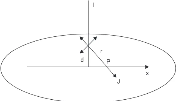
ρε Figure 2. By spherical symmetry, the current density J at a point
P located at a distance r from the source is equal to the total current crossing a spherical surface with radius r.
Figure 3. (A) Three-layer finite element model showing current distribution. Each current electrode is 4 mm in width. (B) Comparison of skin impedance with measuring position. (C) Comparison of skin impedance with the measuring distance. (D) Compari- son of skin impedance with the measuring depth.
Given a monopolar point source in an infinite homoge- neous and isotropic volume conductor connected to a cur- rent source I, the potential and current at any point can be easily derived. By spherical symmetry, the current density J at a point P located at a distance r from the source is equal to the total current crossing a spherical surface with radius r
J = ur . (10)
Where, ur is the unit radial vector, and r is the distance be- tween the electrode and the point of measurement. The elec- trical field is then obtained from eq. (3):
E = ur . (11)
The electrical field is the gradient of the potential. In spher- ical coordinates,
E = ur . (12)
Therefore, the potential at point P is obtained by integra- tion:
ϕ = (13)
III. Results
Figure 3A shows the results of finite-element analysis (FEM) analysis based on the three-electrode method using finite
element simulation for the epidermis, dermis and subcuta- neous In Figure 3B, which shows the results of the computer simulation, current density as the edge of the electrode is higher than that under the electrode. Sections immediately below and at the edge of the measurement electrode were measured at six different depths, revealing that impedance was lower at the edge of the electrode than immediately be- low it. This is because the current density was higher at the edge of the electrode.
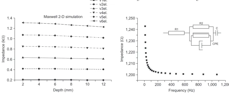
Figure 3C shows how impedance changed with measure- ment distance at different depths, revealing that impedance increased as the measurement distance increased for all depths. Figure 3D shows the results obtained when imped- ance was measured at different depths; here impedance decreased as measurement depth increased. This is because deeper tissues are characterized by lower resistance. In deep layers, the measured impedance was small; in shallow lay- ers, the measured impedance was large. The increment of measuring depth was 2 mm, and the maximum measuring depth was 12 mm. Figure 4 shows results from comparison of skin impedance according to the measuring depth (four electrodes). When the measuring depth is deep, impedance measurement is small and when the measuring depth is shallow, the value for impedance measurement is large.
In this paper, the electrical skin model used (Figure 5) was the one proposed by Grimnes and Martinsen [14]. In this electric model, R1 represents the resistance of internal tissue, the R2 model the resistance of external tissue, and C repre- sents the electrode/tissue interface and constant phase ele- ment model. The equivalent circuit that describes the imped- ance of skin consists of a CPE with ZCPE =Y-1(jω)-α, where α is related to the fractal dimension of the skin’s surface and can be regarded as a measure of the roughness of the skin’s
Figure 4. Result of impedance values when the edge measuring
electrodes using four electrode. Figure 5. Skin impedance is estimated using skin electrical model.
CPE: constant phase element.
I 4πr2
4πσr2 I
dr dϕ
4πσr I
surface, ω is the angular frequency, and Y is the admittance of the CPE. Values of the chosen components were deter- mined via a non-linear least-squares fit to the equivalent cir- cuit using the Z-view program. Results of this fit are shown in Figure 5 and Table 1. This electrical impedance model was fitted and developed in comparison with our model for mea- surement of skin impedance. We obtained accurate results from our developed electric model.
IV. Discussion
In conclusion of simulation, an increase or decrease in impe- dance in the region between the voltage electrodes produced a corresponding increase or decrease in voltage, which is a measurement of the change in impedance within this region.
When the conductivities of the different tissue layers are es- timated, the tissue layer depth can also be estimated simulta- neously by increasing the distance between the current elec- trodes. For simultaneous estimation of the tissue structure and conductivities of different tissue layers, the impedance should be sensitive to changes in the conductivity of each tis- sue layer and changes in each layer depth. Determination of the sensitivity of the change in the conductivity of the tissue to the measured impedance may be possible at some special locations by use of acupuncture points, which have low resis- tance [15]. Voltage can also be increased in order to increase the measured impedance. However, the distance between the current electrodes is more important since the current can flow in the deep layers, which provides information on these layers.
In the present study, the skin impedance measurement method is easily applied and skin impedance depth infor- mation is based on simulations by FEM computer calcula- tion. The effect of the new method is assessed by computer simulations using a typical two-dimensional (2-D) model.
Electrical equivalent circuit is defined as the skin model most similar to that of our proposed Cole mode. From the results obtained, we propose that the report observed in the literature on large dispersion of non-invasiveness impedance
characteristics of the human body. Another conclusion that can be deduced from these measurements is that, to better locate the exact position of an area of skin with low-frequen- cy, measurements in the range of about 200 Hz offer a better opportunity. In the future more in depth research as well as additional studies using other methods of skin impedance should be conducted.
Conflict of Interest
No potential conflict of interest relevant to this article was reported.
Acknowledgements
This research was supported by grant No. RTI04-01-01 from the Regional Technology Innovation Program of the Minis- try of Knowledge Economy (MKE).
References
1. Kinouchi Y, Iritani T, Morimoto T, Ohyama S. Fast in vivo measurements of local tissue impedances using needle electrodes. Med Biol Eng Comput 1997; 35: 486- 492.
2. Davies DJ, Ward RJ, Heylings JR. Multi-species assess- ment of electrical resistance as a skin integrity marker for in vitro percutaneous absorption studies. Toxicol In Vitro 2004; 18: 351-358.
3. Uchiyama T, Ishigame S, Niitsuma J, Aikawa Y, Ohta Y.
Multi-frequency bioelectrical impedance analysis of skin rubor with two-electrode technique. J Tissue Viability 2008; 17: 110-114.
4. Fatouros DG, Groenink HW, de Graaff AM, van Aelst AC, Koerten HK, Bouwstra JA. Visualization studies of human skin in vitro/in vivo under the influence of an electrical field. Eur J Pharm Sci 2006; 29: 160-170.
5. Darlenski R, Sassning S, Tsankov N, Fluhr JW. Non- invasive in vivo methods for investigation of the skin barrier physical properties. Eur J Pharm Biopharm 2009;
72: 295-303.
6. Zhao X, Kinouchi Y, Yasuno E, Gao D, Iritani T, Morim- oto T, Takeuchi M. A new method for noninvasive mea- surement of multilayer tissue conductivity and structure using divided electrodes. IEEE Trans Biomed Eng 2004;
51: 362-370.
7. Lee YK, Woo YJ, Lee CK, Yoo SK. Development of a flexible chest electrode belt for continuous ECG mea- surement. J Korean Soc Med Inform 2008; 14: 287-293.
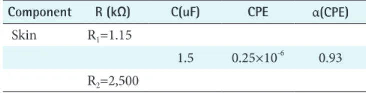
Table 1. Components of parameters for the equivalent electrical circuits used for simulation of skin
Component R (kΩ) C(uF) CPE α(CPE)
Skin R1=1.15
1.5 0.25×10⁻⁶ 0.93 R2=2,500
CPE: constant phase element.
8. Damez JL, Clerjon S, Abouelkaram S, Lepetit J. Dielec- tric behavior of beef meat in the 1–1500 kHz range:
simulation with the Fricke/Cole–Cole model. Meat Sci- ence 2007; 77: 512-519.
9. Yamamoto Y. Measurement and analysis of skin elec- trical impedance. Acta Derm Venereol Suppl (Stockh) 1994; 185: 34-38.
10. Grimnes S. Impedance measurement of individual skin surface electrodes. Med Biol Eng Comput 1983; 21: 750- 755.
11. Martinsen OG, Grimnes S, Karlsen J. Electrical methods for skin moisture assessment. Skin Pharmacol 1995; 8:
237-245.
12. Hua P, Woo EJ, Webster JG, Tompkins WJ. Finite ele-
ment modeling of electrode-skin contact impedance in electrical impedance tomography. IEEE Trans Biomed Eng 1993; 40: 335-343.
13. Tong P, Rossettos N. Finite-element method: basic tech- nique and implementation. Cambridge, MA: MIT Press;
1977. p332.
14. Grimnes S, Martinsen OG. Cole electrical impedance model: a critique and an alternative. IEEE Trans Biomed Eng 2005; 52: 132-135.
15. Colbert AP, Larsen A, Chamberlin S, Decker C, Schiffke HC, Gregory WL, Thong T. A multichannel system for continuous measurements of skin resistance and capaci- tance at acupuncture points. J Acupunct Meridian Stud 2009; 2: 259-268.