Ⅰ. 서 론
임플랜트는 현대 치과의학의 핵심적 관심사의 하나이기에 많은 학자들의 관심을 끌어왔다.
1981년 Albrektsson 등1)은 치과 임플랜트 시술에 서의 성공적인 골유착에 영향을 주는 6가지 요소 에 대하여 논하였는데, 임플랜트 재료의 생체 적합 성, 임플랜트의 외형, 표면 조건, 수용부위의 골 조건, 수술방법, 하중 조건이 그 것이다. 이 중에서 수술 방법은 성공적으로 임플랜트를 하기 위해 임 상 치과의사가 중점 연구하여야 할 부분이며, 여기 에서 드릴링 시 발생하는 열에 대한 연구는 성공적 수술 방법을 위한 중요한 과제이다.
이와같은 발생열에 대한 연구로는 국내에서, 1992년 이 등2)은 성견에 임플랜트 시술 시 골 천 착 회전수와 냉각수 유무에 따른 영향을 연구하였 으며, 1999년 문 등3)은 치과 임플랜트 식립시 관 주에 따른 골 천착 기구의 열 발생에 관한 연구로 천착 열 발생에 대한 연구가 있었다. 1999년 황 등4) 은 열 발생 이외에 임플랜트 임상 논문으로 만 3년 의 93명 환자 243개의 임플랜트를 관찰하는 임상 연구를 하였다.
국외에서는 1983년 Eriksson 등5)은 30마리의 토 끼 장골에 다양한 열을 전도시켜 47℃ 이상에서 골 조직은 열에 의해 괴사를 일으킨다고 하였다.
생체실험에서 1992년 Watanabe 등6)은 드릴 종류 별로 열 발생 변화를 비교하였는데, 천착 직후까지 잔류 열이 상승하는 것을 보고하였다. 1996년 Brisman 등7)은 드릴링의 속도와 압력의 두 변수에
의한 열 변화를 보고하였고, 같은 해 Yacker 등8)은 드릴링 바의 온도가 주위의 골 온도보다 높게 상승 하며 골 온도에 비해 냉각수의 영향을 많이 받는다 고 하였으며, 드릴링 과정 중, 중간에 만나는 치밀 골이 드릴링 바의 온도 상승에 영향을 준다고 하였 다. 이 밖에도 1986년 Erikson 등9)은 낮은 압력으 로 드릴링할 것을 권하였고, 1996년 Brisman7)도 드릴의 회전 속도보다 드릴의 압력이 열 발생에 더 영향을 준다고 하였다. 1992년 Sutter10)는 임플랜 트의 내부 및 외부 냉각 시스템을 비교 실험하였는 데, 실온과 같은 22℃가 아닌 5℃ 냉각수가 열 발 생 방지에 효과적이며 외부냉각에 비해 내부냉각 이 더 큰 효과가 있다고 하였다. 또한 그는 12회까 지의 드릴링은 골 표면에 깨끗한 절단면을 보인다 고 하였다. 횟수에 대해 1996년 Brisman7)은 15회 까지 재 사용이 가능하다고 하였고, 정형외과 분야 에서 1982년 Krause11)는 40회까지 드릴링 바의 재 사용이 가능하다고 하였으며, 같은 정형외과 분 야에서 2000년 Bachus 등12)은 50℃ 이상에서의 천착으로, 천착온도가 떨어진다고 하였는데, 이는 치과 임플랜트와의 천착 소요시간 드릴의 형태 천 착의 제 조건이 다소 다른 것으로 형태와 조건 등 에 따라 다양하게 변화가 있는 폭 넓은 연구가 필 요함을 보여준다.
1990년 이후 순수 천착 드릴의 열 발생에 대한 연구는 1992년의 Watanabe 등6)과 1997년 Codioli 등13), 그리고 1996년 Benington 등14), 1997년 Iyer 등15)과, 1999년 Kerawala 등16)이 있 다. 이들 중 Bra�nemark 임플랜트 계통에서 천착 대한치과보철학회지:Vol. 40, No. 1, 2002
임플랜트 식립부위 형성시 골조직의 온도변화에 관한 연구
서울대학교 치과대학 치과보철학교실 김평일∙김영수∙장경수∙김창회
드릴의 열 발생에 대한 연구는 1996년 Benington 등14)이 유도 드릴인 라운드 바와 2mm 트위스트 드릴 그리고 Pilot 드릴을 대상으로, 적외선 ther- mography를 이용하여, 온도를 계측, 천착열 발생 을 관찰하였었다. 그러나 적외선 thermography는 물 속을 감지 할 수 없어 임상적 환경과 동일한 실 험을 하기는 부적합하다고 볼 수 있었다.
본 연구의 목적은 Bra�nemark 임플랜트 계통의 임상 시술 과정과 유사한 환경에서 임플랜트 식립 부위 형성 과정의 열 발생 정도를 측정하여, 골 조 직에 유해한 자극 정도를 평가하고 그 임상적 의의 를 찾기 위한 연구이다.
이에 저자는 임상환경과 유사한 실험실 조건에 서 각종 드릴링 바와 재 사용 빈도에 따른 열발생 및 소요시간의 변화, 치밀골 조우시 천착 압력 증 가에 따른 영향 등 임상적으로 의미가 있는 정보를 파악하고자, 본 실험을 하여 흥미로운 결과를 얻어 이에 보고하는 바이다.
Ⅱ. 실험 재료 및 방법 1. 실험 기구 및 재료
실험을 하기위한 현가장치는 저자가 설계하여 응용기계사에 의뢰하여 제작하였다. Fig. 1처럼 제작한 현가장치(응용기계사, 한국)는 장치의 수직 방향으로 가설된 천착 삽입로에 평행으로 드릴링 바가 설치 될 수 있도록 핸드피스를 현가시킬 수 있고 또한 이와같은 장치를 천착 삽입로에 수직인 평면상에서 측방 직선상으로 1
μ
m씩 이동할 수 있는 정밀 기구이다. 바이스를 1회전하면 1회전에
100개의 눈금이 이동한다. 1회전에 1mm 이동을 하기에 한 눈금에 1
μ
m씩 이동한다.두께 15�20mm의 소 견갑골을 1변이 35mm 크기가 되도록 정사각형 골편으로 자르고, 이 중에 피질골의 두께가 2�3mm되는 표본을 선정하였다 (Fig. 2). 표본 부피의 1/2을 36.5℃ 생리식염수에, 나머지 1/2를 평균 실온 24.9℃의 공기 중에 노출 시켜 개구 상태의 구강 조건과 유사한, 골 표면온 도 28.1℃, 골 내부온도 31.4℃로 유지 시켰다. 생 리식염수는 수중 모터로 강제 대류하여 전체온도 가 균일하도록 하였다. 정확한 생리식염수의 온도 를 정확하게 유지하기 위하여 전열 가열기(제이오 테크사, 한국)를 수중에 설치하였다(Fig. 2).
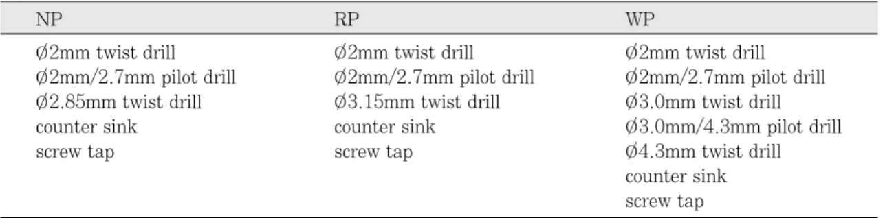
천착에는 Bra�nemark system 드릴 계통을 사용 하였다. 본 실험에서는 유도 드릴의 첫 단계인 라 운드 바를 냉각수의 과도한 영향 등을 고려하여 실 험 대상에서 제외하고, NP 드릴 5단계, RP 드릴 5단계, 및 WP 드릴 7단계를 적용하였다(Table Ⅰ).
각 드릴은 Nobelbiocare사의 드릴 controller(DEA 040), torque controller(DEA 053)를 이용하여 표 본에 천착하였다.
2. 실험 방법
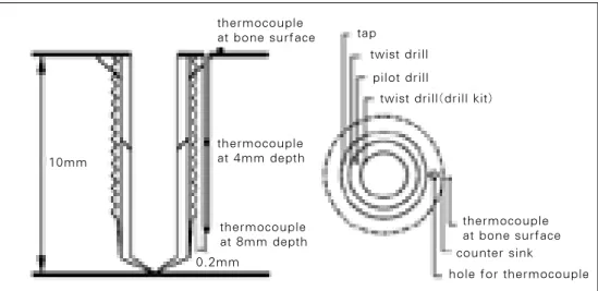
발생 열을 기록하기 위하여 Fig. 3과 같이 ther- mocouple을 표본에 매립하였다. 마지막 천착 과정 인 tapping 바와 0.2mm 거리에서 지름 0.9mm, 깊이 8mm의 thermocouple 삽입 공을 형성하였다.
Tip에서부터 각각 4mm, 8mm 위치에서 120�굽어 있는 두 개의 thermocouple (Fig. 4)을 이용하여, 각각의 깊이로 삽입하여 온도를 측정하였는데, 각
Table Ⅰ. Drills used in the experiment
NP RP WP
O/2mm twist drill O/2mm twist drill O/2mm twist drill
O/2mm/2.7mm pilot drill O/2mm/2.7mm pilot drill O/2mm/2.7mm pilot drill O/2.85mm twist drill O/3.15mm twist drill O/3.0mm twist drill
counter sink counter sink O/3.0mm/4.3mm pilot drill
screw tap screw tap O/4.3mm twist drill
counter sink screw tap
Fig. 1. Precision Handpiece Stand: A precision hand- piece restraining system, designed by the author and fabricated by Eungyong Machinery, Inchon, Korea, that keeps the drill parallel to the drilling path and allows horizontal adjustment of the drill with as lit- tle as 1
μ
mincrement.Fig. 2. For a typical experiment, 35mm square samples of bovine scapular bone were utilized. The sam- ples were approximately 20mm thick with the corti- cal thickness on the drilling side ranging from 1 to 2mm.
A sample was placed in a container of saline solution so that its lower half is submerged into the solution and the upper half exposed to the room air, which averaged 24.9℃. The temperature of the saline solution was main- tained at 36.5℃ using an electric heater (J. O Tech Co., Korea). As the sample was drilled, the generated heat was removed by saline coolant of 24℃.
Fig. 3. The thermocouple insertion hole, that is 0.9mm in diameter and 8mm in depth, was prepared 0.2mm away from the tapping bur, the last drilling step. The temperatures due to countersink, pilot drill, and other drills were measured at the surface of the bone, at the depths of 4mm and 8mm respectively. Countersink drilling temper- ature was measured by attaching the tip of a thermocouple at the rim of the countersink. To assure temperature measurement at the desired depths, “bent-thermocouples”with their tips of 4 and 8mm bent at 120�were used.
thermocouple at bone surface
thermocouple at 4mm depth
thermocouple at bone surface thermocouple
at 8mm depth 0.2mm
tap twist drill
pilot drill
twist drill(drill kit)
counter sink
hole for thermocouple 10mm
드릴의 작용 위치를 고려하여, countersink는 표본 표면, pilot 드릴은 표면에서 4mm, 그 이외의 드릴 의 경우에서는 표면에서 8mm의 위치에서 온도 측정을 하였다(Fig. 3).
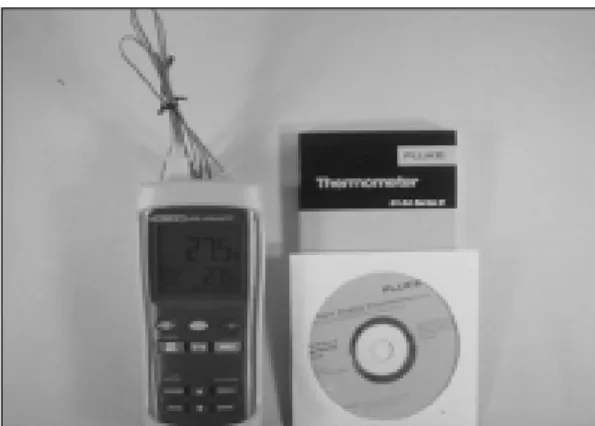
온도 측정은 초 단위 기록 기능으로 조정된 thermometer (Fig. 5)을 이용하여 초 단위 시간에 따라 측정하였다. 천착 중에는 외부 냉각 방식을 적용하였고, 사용된 냉매는 실온에 방치된 평균 24℃의 생리식염수를 사용하였다. 천착 중 발생하 는 온도 상승을 차단하기 위해 1992년 Sutter11)는 5℃, 1999년 Moon 등3)은 15℃이하의 냉각수를 권 장하였지만, 본 연구에서는 일상의 임상 조건에 따 른 실험 환경을 조성하기 위하여 실온에 노출한 냉 각 계통을 선택하였다.
천착 회전수는 Bra�nemark 임플랜트 계통 con- trol set(DEA 040)의 2200rpm으로 시행하여 골 천착하였으며 tapping도 Bra�nemark 임플랜트 계통의 torque controller(DEA 053)로 제조사 의 설명서에 따라 시행하였다.
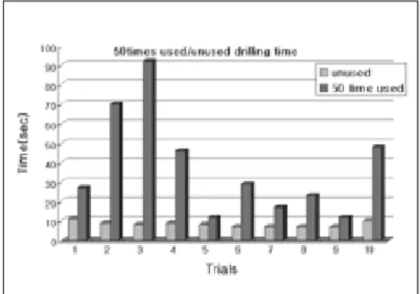
기준천착압력 750g, 천착 깊이 10mm로 드릴의 각 단계를 적용하였다. 각 50회씩 850회 시행하면 서 온도를 측정하였다.
천착열 변화가 다양한 2mm 트위스트 드릴에 대하여 2차 실험을 시행하였다. 천착깊이 10mm, 속도 2200rpm으로 유지하고, 천착 압력을 750g,
1,250g, 1,750g 등 세 단계로 구분하여 각각 10회 씩 총 30회 천착 후 최대 온도를 측정하여 이중 1,250g 천착 압력군과 1,750g 천착 압력군에 대하 여 압력증가에 따른 천착 소요시간과 천착 발생온 도에 대한 소표본 검증을 실시 하였다. 또한 750g 압력군 10회분 실험 성적은, 새 드릴과 재 사용 드 릴을 비교하기 위하여, 41회부터 50회 사용 드릴 의 동일 표본에 천착하여, 재 사용 드릴과 새 드릴 의 드릴 소요시간과 발생열을 비교 조사하였는데, 이중 새 드릴과 재 사용 드릴의 천착소요시간에 대 하여 t-test를 통해 관계를 분석하였다.
각 실험 데이터는 드릴링 바의 재 사용 횟수와 온도 및 시간의 3차원 함수이므로 3차원 그래프로 표시하였다.
Ⅲ. 연구결과
천착된 골질을 확대 천착하는 다른 드릴링 바와 다르게 온전한 골질을 최초로 천착하여야 하는 직 경 2mm 트위스트 드릴은 열 발생에서 가장 주목 을 받았다. 각각의 천착 드릴의 50회 재 사용에서 치밀골 여부를 떠나 2mm 트위스트 드릴 이외의 모든 천착 후속드릴에서는 1983년 Eriksson 등5) 이 주장한 골 손상 역치온도이며 이 연구의 참고기 준온도인 47℃를 넘는 경우는 없었다. 단지 2 mm Fig. 4. The details of “bent thermocouples.”4
and 8mm long thermostat tips were bent at 120�. Insertion of these assured the temperature mea- surement at 4 and 8mm depths respectively.
Fig. 5. The profiles of temperature variation were recorded continuously at one second interval using a thermometer with memory function (Fluke Co., U.S.A.) and 0.7mm thermocouples (Omega Co., U.S.A.).
8mm 4mm
120� 120�
트위스트 드릴 만이 750g으로 천착이 어려운 치밀 골에서 급작스러운 온도 상승을 보였다. 한편 2mm 트위스트 드릴을 제외한 여타의 드릴은 2 mm 트위스트 드릴이 열어놓은 천착 통로를 확대 하는 단순 기능 때문에 치밀골이라 하여도 시간과 열 발생에서 순조로운 모습을 보이는 것 같다(Fig.
14-16, 18-20, 23-27).
이에 따라 2mm 트위스트 드릴에 대하여 2차실 험을 하였다. 50회 재 사용 드릴과 비교하기 위한 별도의 750g 압력군 10회(Fig. 12), 치밀 골을 대 상으로 하여 1,250g, 1,750g의 2개 그룹(Fig. 6, 7)으로 각각 10회씩 총 30회 2차실험을 하였다.
750g으로 천착이 어려운 경우가 850회 천착 가 운데 모두 13회 있었는데, 이 중 500g과 1,000g 의 추를 현가장치에 올려 천착 압력을 가압한 10 회 성적은 Table Ⅱ 및 Fig. 11에 별도 처리 하였 다. 이 부분은 표본 골질 선정이 서툴렀던 첫 실험 NP 시리즈의 것으로, NP 2mm 트위스트 드릴의 16회, 19회, 21회, 35회, 38회는 1,250g의 압력으 로, 17회, 18회, 20회, 36회, 37회는 1,750g의 압 력으로 천착한 경우였다. 이들 10차례 데이터에서 기준 온도 47℃를 훨씬 상회하는 70�80℃로 급격 한 온도 상승을 보였다.
13회중 이상 10회를 제외한 3회는 현가장치에 추를 추가로 올리지 않은 750g으로 실험한 것으 로 NP 14차 47.1℃, RP 28차 63.6℃, WP 1차 59℃ 경우였다. 이중 RP 28차 63.6℃는 실험 기 록에 의하면 천착이 어려워 손가락으로 무의식간 에 천착기구를 눌러 천착 압력을 가압하여 준 경 우였고, NP 14차 47.1℃는 기준 역치온도 47℃
를 0.1℃ 초과한 경우로 750g으로 천착이 가능한 표본에서 기준 역치온도를 현저히 상회는 경우는 WP 1차 59℃ 한가지 경우 이었는데, 이들 3회 모 두 천착 시간이 오래 걸린 것을 감안한다면 (Fig.
10, 17, 22) 3회의 표본이 추를 올려놓아 가압할 만한 치밀골이라고 할 수 있다. 따라서 Bra�ne- mark 임플랜트 계통의 모든 드릴링 바는 제조사 의 냉각 방법 하에서 50회 재 사용까지 천착 압력 750g으로 천착이 무난한 골 조직이라면 역치온도 47℃ 이하로 무리한 열발생을 일으키지 않는다고 할 수 있다.
한편 50회 재 사용 드릴과 비교하기 위한 별도 의 750g 압력군, 10회의 750g의 기준 압력으로 천 착 용이한 표본에서의 결과는 Fig. 12에서 보듯이 체온 주위의 안전한 온도 변화를 보여 주었다. 모 든 천착 드릴에 대하여 천착 소요시간과 천착 최대 발생열에 대한 관계를 통계학적으로 검토한 바, Table Ⅱ에서 2mm 트위스트 드릴은 온도와 시간 에서 다른 드릴보다 높은 표준오차를 보여 변화의 Fig. 6. Increased drilling pressure was necessary for
a dense bone. Fig. 6 shows a large amount of heat generation under the drilling pressure of 1,250g (500g over the reference weight). This sug- gests the likelihood of accidents during clinical practice due to the tendency for application of an exces- sive pressure without realizing it when faced with a dense bone.
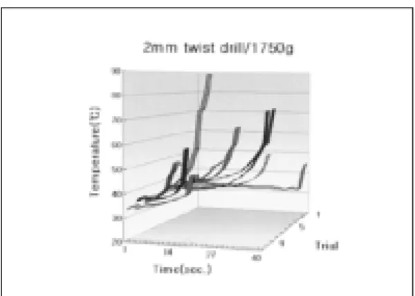
Fig. 7. The effects of increased drilling pressure of 1,750g(1,000g beyond the reference, 750g). Increased drilling pressure shortened the drilling time and increased the temperature. However, time shortening was more prevalent than the temperature rise.
다양성을 보였다. Tap, pilot, countersink의 일부 는 발생열과 소요시간의 음의 상관계수를 보이거 나 0에 가까운 관계를 보여 천착이 계속 되어도 오 히려 발생 열이 떨어지는 모습을 보였다. 이점은 적은 발생 열에 높은 냉각수 효과의 결과라고 할 수 있다.
Table Ⅲ는 가압으로 인한 열 발생 변화를 보기 위한 추가실험에서 1,250g 군과 1,750g 군은 천착 압력 변화에 따른 천착 열과 천착 시간 변화를 관 찰 할 수 있었고 그 내용을 표시 한 것이다.
2차실험에서 현저한 열 상승이 관찰된 것 이외 에 두 압력의 차이가 가져오는 천착 온도와 시간에 Table Ⅲ. Increased drilling pressure becomes necessary in a dense bone. Comparing 2 excessive drilling pressure groups, by means of small sample test, time t statistic=10.80 temperature t statistic=2.08. Time is more influenced than temperature
Drilling Time(sec) corelation Max Temperature(℃) Mean S.D. SEM Mean±SEM coefficient Mean S.D. SEM. Mean±SEM 750g 24.28 23.71 3.35 24.28±3.35 0.372 37.38 9.95 1.41 37.38±1.41 1,250g 99.10 61.70 19.51 99.10±19.51 0.522 51.06 13.19 4.17 51.06±4.17 1,750g 25.00 9.45 2.99 25.00±2.99 0.022 60.60 13.86 4.38 60.60±4.38 Table Ⅱ. Low correlations, or even negative correlations, were observed between drilling time and drilling temperature in case of tap, pilot and countersink. This suggests that these drills are biologically acceptable under the practice conditions that are similar to the experiment. In contrast, significant cor- relations are observed between the time and the temperature in case of 2mm twist drill. This suggests the need for a great deal of care in using such drills. This concern is further amplified because of the large SEM value
Drilling Time(sec) corelation Max Temperature(℃) Mean S.D. SEM Mean±SEM coefficient Mean S.D. SEM. Mean±SEM 2mm twist drill
50 trials 24.28 23.71 3.35 24.28±3.35 0.372 37.38 9.95 1.41 37.38±1.41 40trials 23.53 25.22 3.98 23.53±3.99 0.590 33.68 4.03 0.64 33.68±0.64 NP plus weight 27.30 17.09 5.40 27.30±5.40 0.709 52.18 12.84 4.06 52.18±4.06
Pilot 3.00 1.20 0.17 3.00±0.17 0.165 32.64 2.885 0.41 32.64±0.41
Twist 2.82 0.77 1.11 2.82±1.11 0.173 32.57 2.587 0.37 32.57±0.37
Countersink 3.34 1.15 0.16 3.34±0.16 0.143 30.58 1.627 0.23 30.58±0.23 Screw Tap 73.03 21.57 3.05 73.03±3.05 0.257 30.34 1.243 0.18 30.34±0.18 2mm twist dril 17.66 11.51 1.63 17.66±1.63 0.464 35.40 5.047 0.91 35.40±0.91
Pilot 3.62 1.97 0.28 3.62±0.28 0.144 34.90 2.434 0.34 34.90±0.34
RP Twist 3.24 1.20 0.17 3.24±0.17 0.461 35.39 3.384 0.48 35.39±0.48 Countersink 4.38 1.26 0.18 4.38±0.18 0.126 33.14 2.826 0.40 33.14±0.40 Screw Tap 80.10 12.71 1.80 80.10±1.80 ‐ 0.326 31.17 1.575 0.22 31.17±0.22 2mm twist drill 32.36 29.66 4.19 32.36±4.19 0.594 34.82 4.43 0.63 34.82±0.63
Pilot 3.40 1.11 0.16 3.40±0.16 -0.005 34.73 2.20 0.31 34.73±0.31
Twist 3.24 0.62 0.09 3.24±0.09 0.150 33.81 2.30 0.33 33.81±0.33
WP Pilot 3/4.3 3.40 1.62 0.23 3.40±0.23 0.132 34.49 1.67 0.24 34.49±0.24 Twist 4.3 3.24 0.59 0.08 3.24±0.08 0.169 34.54 2.35 0.33 34.54±0.33 Countersink 3.42 0.88 0.12 3.42±0.12 -0.202 30.45 1.43 0.20 30.45±0.20 Screw Tap 57.56 16.01 2.26 57.56±2.26 -0.049 30.72 1.08 0.15 30.72±0.15
Table Ⅳ. The effects of the age of 2mm twist drills on drilling time and temperature. Between the first 10 drillings of a new drill and 10 drillings of an old one after 40 drillings. remarkable change in drilling time was observed using the same specimen. Time change t-test statistic for was 3.49. No significant difference in drilling temperatures were observed between the new and old drill
Drilling Time(sec) Max Temperature(℃)
mean SD SEM mean±SEM mean SD SEM mean±SEM
1-10 trials 8.30 1.42 0.45 8.30±0.45 35.79 1.74 0.55 35.79±0.55
41-50 trials 37.60 26.50 8.38 37.60±8.38 33.88 2.19 0.69 33.88±0.69 미치는 영향을 아울러 조사 할 수 있었다. 소표본
검정방법을 적용, 얻어진 천착 시간과 천착 열의 관계는 다음과 같다.
시간 : t 통계량 = 10.8 유의수준 5% 뿐 만 아니라 0.1 에서도 1,250g 에서의 시간이 1,750g 에서의 시 간보다 크다.
온도 : t 통계량 = 2.08 이 경우에는 유의수준 5%에서는 1,750g 실험의 온도가 1,250g 실험의 온도보다 크다고 할 수 있으나 유의수준 2.5%에서는 두 경 우의 차이가 있다고 할 수 없다.
즉 열 발생의 경우에는 만일 5%의 판단오류를 범하는 것을 가정하면 두 경우가 차이가 있다고 말
할 수 있으나, 2.5%의 판단오류만을 가정하면 차 이가 없다는 뜻으로, 천착 압력이 증가함으로 천착 온도는 오르고 천착 시간은 줄어들어 서로 반비례 하는데 시간의 감소가 더 뚜렷하다는 결과이다.
한편, Table Ⅳ에서 천착 압력 750g으로 직경 2mm 트위스트 드릴에서 첫 10회 사용 드릴과 41 회부터 50회 사용 드릴을 동일 표본에 드릴링 하 여 삭제 시간과 발생열에 대하여 50회 재 사용 드 릴과 사용치 않은 새 드릴의 드릴 소요시간과 발생 열을 비교 조사하는데, 이중 차이가 현격한 Fig. 5 의 소요시간에 대하여 t-test를 시행하여 다음의 결과를 얻었다.
Fig. 8. Under the drilling pressure of 750g, it was revealed that there was no significant difference in drilling temperature between a new drill and an old twist drill that has already drilled 40 times.
Fig. 9. Under the drilling pressure of 750g, it was revealed that the drilling time for an old twist drill that has already drilled 40 times was 4.5 times longer than a new drill. The measurement was taken for the first ten drilings of a new drill and the 10 drillings of an old drill that has already used for 40 drilling. “Test Statistics”of small samples t-test was 3.49, confirming that the used twist drills require longer drilling time than new ones.
t-test 분석 결과
새 2mm 트위스트 드릴과 50회 사용 2mm 트위스트 드릴 이 보인 천착시간이 각각 8.3초와 37.6초로 매우 크지만, 또한 분산이 1.42와 26.50으로 후자의 분산 값이 매우 불 안정하였다. 그러나 큰 시차를 보여 소표본 t-test의 검정통 계량값은 3.49이며 5%와 1% 유의수준에서 모두 차이가 있어 확실한 차이를 보였다.
열 발생에 대하여도 t-test를 하였으나 이때 열 전쌍 위치가 전자와 후자가 각각 0,2mm, 1.7 mm의 간격으로 2mm 트위스트 드릴과 계측 거리 의 차이가 있어, 새 드릴 쪽이 열 감지 거리가 더 가까워 t-test 대상이 되지 못하였고, 거리가 가까 운 관계로 새 드릴 쪽이 온도가 다소 높아야 하는 데, 그 차이가 1.91℃라는 근소한 차이이며, Table
Ⅳ와 같이 전자, 후자의 표준오차가 0.55와 0.69로 0과 1사이의 작기 때문에 온도차이는 거의 없다고 할 수 있다.
Ⅳ. 총괄 및 고안
열 손상을 일으키는 인자로 온도와 그 온도에 노 출시간을 줄이는 것은 성공적인 임플랜트를 위한 중요 사항이다. 또한 실험의 기준을 위하여 골조직 의 온도변화의 기준 온도를 골손상 역치 온도로 설 정하는 것은 조직의 위해 여부에 관한 기준과 일치 하기에 논의 대상이다. 생체의 열 손상 역치에 대 하여 1947년 Moritz 등17)은 44℃의 물을 6시간 피 부에 접촉 하였을 때 비가역적 손상을 받는다고 하 였으며, 1954년 Sevit18)는 41�45℃ 사이에서 화 상이 발발하는 역치라고 하였다. 1983년 Eriksson 등5)은 토끼 장골에 다양한 열을 전도하여 47℃가 골의 열 손상 역치라고 하였다. 1972년 Mathews 등19)은 골 형성 관여 효소인 알칼린 포스페이타제 가 파괴되는 56℃를 역치온도로 주장 하였는가 하 면 똑 같 은 효 소 의 파 괴 온 도 를 1986년 Albrektsson 등20)은 43℃라고 주장하였다. 2000년 Bachus 등12)은 소의 대퇴골과 사람의 대퇴골은 현미경적 구조가 달라 동물 실험으로 사람의 골 손 상 역치 온도를 알 수 없으므로 많은 문헌을 근거 로 하여 50℃ 정도로 손상 역치를 정하기도 하였 다. 이와 같은 여러 논의에서 골조직 위해 온도는
43℃ 이상 50℃ 주위라고 추정할 수 있으며 그 중 간인 1983년 Eriksson 등5)이 주장한 골 손상 역치 온도 47℃를 본 연구의 기준 역치 온도로 정하였다.
천착 중에서 열 발생을 야기하는 인자들에 대하 여 시술자, 드릴 디자인, 수혜자의 측면에서 고려 하여 고찰할 수 있다. 시술자의 측면을 고려하면 1986년 Eriksson 등9)은 표준화하지는 않았으나 드 릴 링 시 낮 은 압 력 을 권 고 하 였 다 . 1996년 Brisman7)은 드릴의 회전 속도보다 드릴에 주어지 는 압력의 영향이 더 크다고 하였다. 1997년 Abouzgia21)는 천착시간을 줄이기 위하여 고속으로 큰 힘을 가하는 것이 바람직 한데, 압력은 2kg 이 내이어야 한다고 하였다. 또한 1997년 Cordioli 등
13)도 드릴에 2kg/2000rpm 이상의 부하를 주지 않 아야 한다고 하였는데 임상적으로는 2,000g은 매 우 큰 압력이다. 이외에도 Eriksson 등5)은 높은 토크에 낮은 스피드가 바람직하다고 하다고 하였다.
1996년 Yacker8)와 1997년 Cordioli 등13)은 직 경이 제일 작은 최초의 천착에 열 발생 문제가 있 다고 하였는데 이 연구에서 직경 2mm 트위스트 드릴의 실험 성적과 그 내용이 잘 일치 하였다. 직 경이 제일 작은 천착드릴은 온전한 골질을 천착 하 기 때문에 그 후속 드릴들의 천착공 확대 기능에 비해 골 마찰이 현저히 많은 것이 열 발생 문제를 일으키는 것 같다.
1997년 Abouzgia 등21)과 Cordioli 등13)은 2kg 이 상의 부하를 주지 않아야 한다고 하였다. 소의 견 갑골에서 대부분이 750g으로 천착이 가능하였으 며 1,750g으로는 가장 치밀한 골질도 용이하게 천 착을 할 수 있었다. 2kg은 매우 큰 압력으로 동양 인의 악골에서 감내하기 힘들 것 같다. 2차실험 1,250g과 1,750g 부하의 실험 군에서 천착 10회 이내에서도 심하게 높은 열을 발생하였다. 1,250g 및 1,750g 천착 압력 하에 격렬한 열 발생은 Fig.
6과 Fig. 7에서 보여주는데 이는 Fig. 17의 RP 2mm 트위스트 드릴 28회에서 무의식중 주어진 압력으로 보여준 온도 상승과 매우 유사 하였다.
이는 임상 시술 시 만나는 치밀골에서 무의식간에 술자가 힘을 가하면 이와 같은 열 변화가 있을 것 으로 예측 할 수 있다.
본 실험의 기준압력 750g은 동양인 술자들의 악 력에 적절한 압력이다. 750g의 천착 압력으로는
직경 2mm 트위스트 드릴을 제외한 모든 천착 시 스템에서, 50회에 달하는 천착 횟수에 불구하고 문제를 발생하지 않았다.
골 천착 시 치밀골을 만나면 2mm 트위스트 드 릴은 제자리 회전을 하다 급격히 관통하게 되는데, 급격한 관통 순간에 온도는 급상승하였다. 2mm 트위스트 드릴의 모든 그래프에서 보이는 급상승 곡선은 대부분 단위시간 1초 내외에 급격한 온도 상승을 보여, 온도 상승은 천착 최종 시기에 최대 의 상승 점을 보였다. 이러한 현상을 관찰하면서, 1991년 Wa¨chter 등22)의 지속적인 천착보다는 간 헐적인 천착이 온도 상승을 낮춰 준다는 보고를 고 려하면, 천착 말기 순간 최대 상승 점에 이르는 시 간대까지 천착을 계속 하지말고 천착을 간헐적으 로 하면서 휴지기간에 천착공에 냉각수를 계속 넣 어주는 것이 바람직하다고 하겠다.
Fig. 9에서 50회 재 사용 실험에서 드릴링 시간 은 재 사용 빈도에 따라 증가하여 천착 압력 750g WP 50회 중 마지막 10회 실험을 마친 동일 표본 에 같은 천착 압력으로 처음 사용하는 2mm 트위 스트 드릴을 10회 실시한 바, 50회 삭제 2mm 트 위스트 드릴이 처음 사용한 것보다 평균 4.5배에 달하는 천착시간이 소요되었으며 t-test의 검정통 계량값은 3.49였다. 한편 동일 실험에서 열 발생은 Fig. 8에서와 같이 새 드릴과 50회 사용 드릴 사이 에 유의한 차이가 없었으므로, 750g의 천착 압력과 제조사가 권하는 냉각수의 영향 하에서는 드릴 재 사용이 열 발생에 큰 문제가 없고 드릴링 시간 지 연에 더 많은 영향을 주는 것을 알 수 있었다.
2mm 트위스트 드릴에서 1,250g과 1,750g으로 대비한 2차 실험에서는 골질이 비교적 단단한 표 본으로 실험하였는데 기복이 심한 온도 상승을 보 여 10회 이내에 골 조직 손상 역치온도 47℃가 훨 씬 넘는 79.8℃까지 계측되었다. 따라서 임상 시술 시 치밀골 천착시 온도 상승에 대한 세심한 주의가 강조된다.
Table Ⅱ에서 RP, WP의 screw tap과 WP의 pi- lot, countersink는 발생열과 천착시간의 관계에서 음의 관계 상관 지수를 나타내어 천착 시간이 진행 될수록 온도가 낮아졌다. 이것은 냉각수의 냉각 효 과의 영향이 매우 유효하다는 것을 보였다.
치밀골 여부와 무관하게 초기 드릴 kit로써
2mm 트위스트 드릴 이후의 후속 드릴인 pilot에서 tap까지 모든 드릴은 체온 수준의 낮은 천착 온도 와 5초 이내의 천착시간의 성적을 얻어 안전한 시 술을 할 수 있다고 볼 수 있다. Tapping은 1분을 넘는 시간이 흔히 소요되었는데 온도가 현저하게 낮아 생물학적으로 적합했다.
이런 점은 2mm 트위스트 드릴을 제외한 여타의 드릴이 2mm 트위스트 드릴이 열어놓은 천착 통로 를 확대하는 단순 기능 때문에 치밀골일지라도 시 간과 열 발생에서 순조로운 모습을 보였다. 냉각 효과로 체온보다 높지 않은 발열, 짧은 천착시간을 보이는 Fig. 14�16, 18�20, 23�27은 이러한 점 을 잘 보여 주고 있다.
Fig. 6, 7의 2차실험에서 천착 압력의 차이가 가 져오는 천착 온도와 천착 시간에 미치는 영향을 보 면 천착 압력이 증가함으로 천착 온도는 오르고 천 착 시간은 줄어들어 서로 반비례하는데 시간의 감 소가 더 뚜렷하여, 천착 압력의 증가로 증가하는 온도와 반비례로 감소하는 시간 두 변수중에 시간 이 더 큰 영향을 받는 다는 것도 이 연구의 작은 소득이다.
Ⅴ. 결 론
저자는 임플랜트 식립 부위 형성 과정의 열 발생 을 연구할 목적으로 이 실험을 하였다. 우골을 대상 으로, 임상적 환경과 유사한 조건하에, Bra�nemark 임플랜트 계통의 드릴링 바를 사용하여 750g, 1,250g, 1,750g의 압력으로 천착 실험하여, 발생열 과 소요시간에 대한 임상적 의의를 찾아 다음과 같 은 결론을 얻었다.
1. 제조사 추천 냉각 방식으로 천착 압력 750g 하 에서 50회까지 드릴을 재 사용하였을 때 온도 변화는 거의 없었고, 드릴의 재 사용 빈도에 따 라 천착 시간은 연장되었다.
2. 천착시 열 발생은 최초의 골 천착을 주도하는 2mm 트위스트 드릴에 문제가 있었고, 그 후속 드릴은 큰 문제는 없었다.
3. 제조사 추천 냉각 방식임에도 최초의 2mm 트 위스트 드릴은 천착 중 치밀 골에 도달하였을 때 천착압력을 높여 주면 급격한 온도 상승을 보였다.
4. 천착 열은 최종 천착 시기에 가장 높았고 천착 종료 후까지 다소 상승하였다.
참고문헌
1. Albrektsson T, Bra�nemark PI, Hansson HA, Lindstro J. Osseointegrated titanium im- plants. : Requirements for ensuring a long lasting, direct bone ankorage in man.
Acta Orthop Scand 1981;52:155-170.
2. Lee JG, Yang JH, Lee SH. A study on the effect of rotational speeds of the trephine mill on the temperature of surrounding bone during dental implantation procedure and osseointegration of implants. J Kor Academy of Pros 1992;30:167-190.
3. Moon ES, Lim HS, Cho IH. A study on the heat generation of bone drilling burs ac- cording to irrigation during implantation of dental implant. J Kor Academy of Pros 1999;37:433-453.
4. Hwang HW, Lee SC, Kim YG, Ryu DM, Lee BS, Clinical study of dental implant : requirements for successful osseointegra- tion. KAID 1999;18:1-9.
5. Eriksson A, Albrektsson T. Temperature threshold levels for heat-induced bone tissue injury : A vital microscopic study in rabbit. J Prosthet Dent 1983;50:101- 107.
6. Watanabe F, Tawade Y, Komatus S, Hata Y. Heat distribution in bone during prepa- ration of implant sites: heat annalysis by real-time thermography. Int J Oral Maxillofac Implants. 1992;7:212-219.
7. Brisman DL. The effect of speed, pressure, and time on bone temperature during the drilling of implant sites. Int J Oral Maxillofac Implants 1996;11:35-37.
8. Yacker M, Klein M.: The effect of irriga- tion on osteotomy depth and bur diameter.
Int J Oral Maxillofac Implants.,
1996;11:634-638.
9. Eriksson R, Adell. Temperature during drilling for the placement of implants us- ing the osseointegration technique. J Oral Maxllofac Surg 1986;44:4-7.
10. Sutter F, Krekeler G, Schwammerger AW, Sutter FJ. Atraumatic surgical tech- nique and implant bed preperation.
Quintessence Int 1992;23:811-816.
11. Krause WR, Bredbury DW, Kelly JE, Lunceford EM. Temperature elevation in orthopedic cutting operations. J Biomech Eng 1982;15:267-275.
12. Bachus KN, Rondina MT, Hutchinson DT. The effects of drilling force on cortical temperatures and their duration: an vit- ro study. Medical Engineering & Physics 2000;22:685-691.
13. Cordioli G, Majzoub Z. Heat generation dur- ing implant site preparation. An in vitro study. Int J Oral Maxillofac Implants 1997;12:186-193.
14. Benington IC, Biagioni PA, Crossey PJ.
Hussey DL, Sheridan S, Lamey PJ.
Temperature changes in bovin mandibu- lar bone during implant site preperation:
an assessment using infra-red thermog- raphy. J Dent 1996;24:263-267.
15. Iyer S, Weiss C, Mehta A. Effects of drill speed on heat production and the rate and quality of bone formation in dental im- plant osteotomies. Part 1 : Relatationship between drill speed and heat production.
Int J Prosthodont 1997;10:411-414.
16. Kerawala CJ, Martin IC, Allan W, Williams ED. The effects of operature technique and bur design on tempera- ture during osseous preparation for os- teosynthesis self-tapping screws. Oral Surg Oral Med Oral Pathol Oral Radiol Endod 1999;88: 145-150.
17. Moritz AR, Henriques FC Jr. Studies of
thermal injury. Am J Path 1947;23:695- 720.
18. Sevitt S. Pathological sequelae of burns.
Proc R Soc Med 1954;47:225-228.
19. Mathews LS, Hirsch C. Temperatures measured in human cortical bone when drilling. J Bone Joint Surg 1972;54:297- 308.
20. Albrektsson T, Zarb G, Worthington P, Eriksson A. The long-term efficacy of
currently used dental implants. A review and proposed criteria for success. Int J Oral Maxillofac Implants 1986;1:11-25.
21. Abouzgia MB, James DF. Temperature rise during drilling through bone. Int J Oral Maxillofac Implants 1997;12:342-353.
22. Wa¨chter R, Stroll P. Increase of temper- ature during osteotomy. In vitro and in vi- vo investgations. Int J Oral Maxillofac Surg 1991;20:245-249.
Reprint request to:
Pyung-Il Kim, D.D.S., M.S.D.
Department of Prosthodontics, Graduate School, Seoul National University 28-1, Yeongun-Dong, Chongno-Gu, Seoul, 110-749, Korea
Tel. 82-2-2634-0406
E-mail. [email protected]
EXPLANATIONS OF FIGURES F
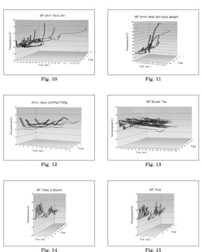
Fiigg.. 1100.. Of the forty cases of normal bone drilling with NP 2mm twist drill under the pressure of 750g, only one case showed 47.1℃, which is higher than the threshold temperature but by merely 0.1℃.
F
Fiigg.. 1111.. Ten cases of drilling a dense bone with NP 2mm twist drill with the cutting pressure of 1,250 or 1,750g. This shows a temperature rise far higher than 47℃, the threshold temperature that a bone tissue can endure.
F
Fiigg.. 1122.. Additional 10 cases of drilling a normal bone with a NP 2mm twist drill under the pres- sure of 750g. Successive drilling within 11 seconds under the pressure of 750g did not show any rise of temperature.
F
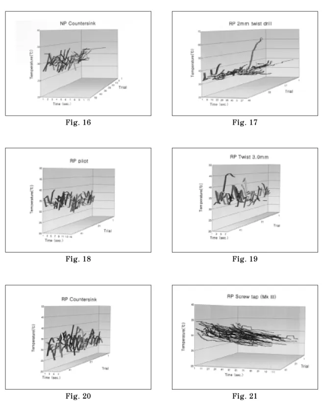
Fiigg.. 1177.. Of the 50 cases of drilling by RP 2mm twist drill under the drilling pressure of 750g, one case (28th drilling-trial) showed the temperature of 63.6℃, substantially higher than the threshold temperature. However, a review of the record of the experiment revealed that an extra finger pressure was added inadvertently during 28th drilling. This is much like a practitioner increasing his finger pressure without realizing it when the drilling is not as easily done as desired.
F
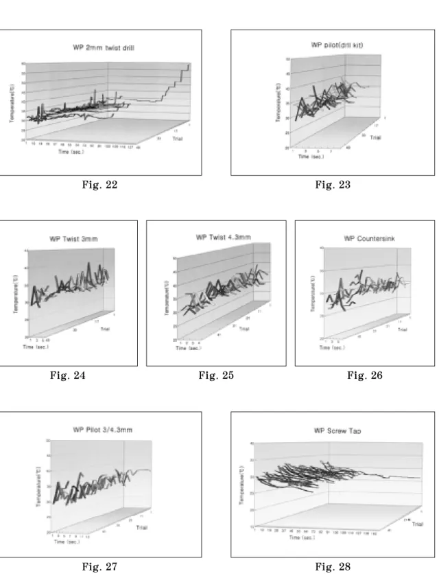
Fiigg.. 2222.. All the 50 cases of drilling by WP 2mm twist drill were done under the drilling pressure of 750g. Only 1 case (1st trial) showed the temperature above the threshold at 59℃.
F
Fiigg.. 1144--1166,, 1188--2200,, 2233--2277.. All the drills that follows a 2mm twist drill, i.e. pilot, twist, coun- tersink of NP, RP, WP, show that they are easy on bone tissues: drilling temperatures are near the body temperature and drilling time is short within 10 seconds. This is be- cause all of such drills drill along the insert way that is already prepared by a 2mm twist drill.
F
Fiigg.. 1133,, 2211,, 2288.. It can be noticed that, for all screw taps of NP, RP, WP, the drilling time in- creases as the “age”of the drill increases, and that the temperature decreases as the drilling progresses, probably owing to cooling by water.
사진부도 ①
Fig. 10 Fig. 11
Fig. 12 Fig. 13
Fig. 14 Fig. 15
사진부도 ②
Fig. 16 Fig. 17
Fig. 18 Fig. 19
Fig. 20 Fig. 21
사진부도 ③
Fig. 22 Fig. 23
Fig. 24 Fig. 25 Fig. 26
Fig. 27 Fig. 28
The purpose of this study is to examine the possibility of thermal injury to bone tissues during an implant site preparation under the same condition as a typical clinical practice of Bra�nemark implant system. All the burs for Bra�nemark implant system were studied ex- cept the round bur. The experiments involved 880 drilling cases: 50 cases for each of the 5 steps of NP, 5 steps of RP, and 7 steps of WP, all including srew tap, and 30 cases of 2mm twist drill.
For precision drilling, a precision handpiece restraining system was developed(Eungyong Machinery Co., Korea). The system kept the drill parallel to the drilling path and allowed horizontal adjustment of the drill with as little as 1
μ
m increment. The thermocouple insertion hole. that is 0.9mm in diameter and 8mm in depth, was prepared 0.2mm away from the tapping bur, the last drilling step. The temperatures due to countersink, pilot drill, and oth- er drills were measured at the surface of the bone, at the depths of 4mm and 8mm respectively.Countersink drilling temperature was measured by attaching the tip of a thermocouple at the rim of the countersink. To assure temperature measurement at the desired depths, “bent- thermocouples”with their tips of 4 and 8mm bent at 120�were used. The profiles of tem- perature variation were recorded continuously at one second interval using a thermometer with memory function (Fluke Co., U.S.A.) and 0.7mm thermocouples (Omega Co., U.S.A.).
To simulate typical clinical conditions, 35mm square samples of bovine scapular bone were utilized. The samples were approximately 20mm thick with the cortical thickness on the drilling side ranging from 1 to 2mm. A sample was placed in a container of saline solution so that its lower half is submerged into the solution and the upper half exposed to the room air, which averaged 24.9℃. The temperature of the saline solution was maintained at 36.5℃ using an electric heater (J. O Tech Co., Korea). This experimental condition was similar to that of a patient’s opened mouth.
The study revealed that a 2mm twist drill required greatest attention. As a guide drill, a twist drill is required to bore through a “virgin bone,”rather than merely enlarging an already drilled hole as is the case with other drills. This typically generates greater amount of heat. Furthermore, one tends to apply a greater pressure to overcome drilling difficulty, thus producing even greater amount heat.
150 experiments were conducted for 2mm twist drill. For 140 cases, drill pressure of 750g was sufficient, and 10 cases required additional 500 or 100g of drilling pressure. In case of
A STUDY ON THE TEMPERATURE CHANGES OF BONE TISSUES DURING IMPLANT SITE PREPARATION
Pyung-Il Kim, D.D.S., M.S.D.,Yung-Soo Kim, D.D.S., M.S.D.,Ph.D., M.Sc.<O.S.U.>
Kyung-Soo Jang, D.D.S., M.S.D., Ph.D., Chang-Whe Kim, D.D.S., M.S.D., Ph.D.
Department of Prosthodontics, Graduate School, Seoul National University ABSTRACT
the former, 3 of the 140 cases produced the temperature greater than 47℃, the threshold temperature of degeneration of bone tissue (1983. Eriksson et al.5)) which is also the ref- erence temperature in this study. In each of the 10 cases requiring extra pressure, the tem- perature exceeded the reference temperature. More significantly, a surge of heat was ob- served in each of these cases.
This observations led to addtional 20 drilling experiments on dense bones. For 10 of these cases, the pressure of 1,250g was applied. For the other 10, 1,750g were applied. In each of these cases, it was also observed that the temperature rose abruptly far above the thresh- old temperature of 47℃, sometimes even to 70 or 80℃. It was also observed that the in- creased drilling pressure influenced the shortening of drilling time more than the rise of drilling temperature. This suggests the desirability of clinically reconsidering application of extra pressures to prevent possible injury to bone tissues.
An analysis of these two extra pressure groups of 1,250g and 1,750g revealed that the t-statistics for reduced amount of drilling time due to extra pressure and increased peak temperature due to the same were 10.80 and 2.08 respectively suggesting that drilling time was more influenced than temperature.
All the subsequent drillings after the drilling with a 2mm twist drill did not produce ex- cessive heat, i.e. the heat generation is at the same or below the body temperature level.
Some of screw tap, pilot, and countersink showed negative correlation coefficients between the generated heat and the drilling time, indicating the more the drilling time, the lower the temperature.
The study also revealed that the drilling time was increased as a function of frequency of the use of the drill. Under the drilling pressure of 750g, it was revealed that the drilling time for an old twist drill that has already drilled 40 times was 4.5 times longer than a new drill. The measurement was taken for the first 10 drilings of a new drill and 10 drillings of an old drill that has already been used for 40 drillings. “Test Statistics”of small samples t-test was 3.49, confirming that the used twist drills require longer drilling time than new ones. On the other hand, it was revealed that there was no significant difference in drilling temperature between the new drill and the old twist drill.
Finally, the following conclusions were reached from this study:
1. Used drilling bur causes almost no change in drilling temperature but increase in drilling time through 50 drillings under the manufacturer-recommended cooling conditions and the drilling pressure of 750g.
2. The heat that is generated through drilling mattered only in the case of 2mm twist drills, the first drill to be used in bone drilling process; for all the other drills there is no significant prob- lem.
3. If the drilling pressure is increased when a 2mm twist drill reaches a dense bone, the tem- perature rises abruptly even under the manufacturer-recommended cooling conditions.
4. Drilling heat was the highest at the final moment of the drilling process.
Key words : Drilling heat generation, Thermocouple, Drilling pressure, Drilling time, Reusing drills, 2mm twist drill.