Preparation of Carbon-TiO2 Composites by Using Different Carbon Sources with Titanium n-Butoxide and Their Photocatalytic Activity
Ming-Liang Chen, Feng-Jun Zhang*, Kan Zhang, Ze-Da Meng, and Won-Chun Oh† Department of Advanced Materials & Science Engineering, Hanseo University,
Seosan-si, Chungnam-do, Korea, 356-706
*Anhui Key Laboratory of Advanced Building Materials, Anhui University of Architecture, Anhui Hefei, P. R China, 230022
(Received November 16, 2009, Revised December 9, 2009, Revised & Accepted December 11, 2009)
여러 가지 탄소 전구체와 TNB를 이용하여 탄소-TiO2 복합체를 제조 및 그들의 광촉매 특성
진 명 량 ․ 장 봉 군*․ 장 간 ․ 맹 칙 달 ․ 오 원 춘†
한서대학교 신소재공학과, *안휘건축대학 안휘첨단건축재료연구실
(2009년 11월 16일 접수, 2009년 12월 9일 1차 수정, 2009년 12월 11일 수정 및 채택)
ABSTRACT:We used activated carbon (AC), activated carbon fiber (ACF) and multi-walled carbon nanotube (MWCNT) as carbon sources and titanium n-butoxide as titanium source to prepare carbon-TiO2 composites. For characterization their properties, scanning electron microscopy (SEM), transmission electron microscopy (TEM), BET surface area, X-ray diffraction (XRD) and energy dispersive X-ray analysis (EDX) were used. And the photoactivity of the carbon-TiO2 composites, under UV irradiation, was tested using the fixed concentration of methylene blue (MB, C16H18N3S·Cl·3H2O) in aqueous solution.
After UV irradiation for a certain time, the concentration of MB solution was determined by UV-vis absorption spectroscopy.
요 약:우리는 탄소 전구체로 활성탄 (AC), 활성탄 섬유 (ACF)와 탄소나노튜브 (MWCNT)와 티타늄 전구체로써 TNB를 사용하여 탄소-TiO2 복합체를 제조하였으며, 이들의 특성을SEM, TEM, BET, XRD와 EDX를 이용하여 분석하였다. 그리고 이들의 광촉매 활성은 UV 램프 조사에서 일정한 농도의 MB 용액을 이용하여 측정하였다. UV 조사한 후에 MB의 농도는 UV-vis 분광광도기를 이용하여 측정하였다.
Keywords:Carbon source; Titanium n-butoxide; TEM; Photocatalytic decomposition
†Corresponding Author. E-mail: [email protected]
Ⅰ. Introduction
Titanium (IV) dioxide or titania (TiO2) has been recognized as one of the most important oxide used in industrial applica- tions because of its physical and chemical properties, such as catalytic activity,1 photocatalytic activity for pollutant re- moval,2 good stability toward adverse environment,3 sensitivity to humidity and gas,4 dielectric characteristic,5 photo-electro- chemical conversion,6 nonlinear optics,7 photoluminescence.8 Its applications include the use as catalysts, catalyst supports, cosmetics, pigments and filler coating. Nevertheless, photo- catalysis is one of the most important uses of titania. Titania is known to have three natural polymorphs: rutile, anatase, and brookite. Rutile is thermodynamically stable polymorph, but anatase is more suitable form for catalytic applications.
Several attempts have been adopted to enhance the photo- catalytic performance of TiO2, such as immobilization of TiO2
powder onto supports like activated carbon (AC),9-20 activated carbon fiber (ACF)21 and so on. AC is highly adsorptive ow- ing to its developed pore structure and high specific area;
moreover the particle size of commercial AC is usually in the micro-scale range. Comparing with AC, ACF are produced in the form of felt or cloth, with high BET surface area and micropore volume.22 Moreover, since the discovery of carbon nanotubes (CNT) efforts have been made to explore their ap- plications using various approaches,23 as they are in fact one of the most remarkable emergent materials. Especially, Multi-walled carbon nanotube (MWCNT) offers enormous po- tential for their high electron-carrying capability, high thermal conductivity and high mechanical strength. MWCNTs are the best candidates for the preparation of photocatalytic compo- sites.23-24
As we studied the performance of C/TiO2 composites pre-
pared from activated carbon, activated carbon fiber and carbon nanotube. So in this paper, we did a comparison of three kinds of carbon-TiO2 composites prepared from activated carbon (AC), activated carbon fiber (ACF) and multi-walled carbon nanotube (MWCNT) with titanium n-butoxide (TNB), re- spectively, and determined the influence of carbon sources on the photocatalytic activity. To compare the properties of these carbon-TiO2 composites, the corresponding composites were characterized by scanning electron microscopy (SEM), trans- mission electron microscopy (TEM), BET surface area, X-ray diffraction (XRD) and energy dispersive X-ray analysis (EDX).
To compare the photocatalytic decomposition, the carbon-TiO2
composites were also determined by the methylene blue (MB, C16H18N3S·Cl·3H2O) in an aqueous solution under UV irradia- tion.
Ⅱ. Experimental
1. Materials
Activated carbon (AC, ca. 80 μm), activated Carbon Fiber (ACF) and multi-walled carbon nanotube (MWCNT, diameter:
~ 20 nm, length: ~ 5 μm) as carbon sources, were purchased from Dong Yang Carbon Co., Ltd (Korea), EAST ASIS Carbon Fibers Co., Ltd (China) and Nanokanbon Co., Ltd (Korea), respectively. Titanium n-butoxide (TNB, Ti{OC (CH3)3}4, 97%) as a titanium source for the preparation of carbon-TiO2 composites was purchased from Acros Organics (New jersey, USA). For the oxidization the surface of MWCNTs, m-chlorperbenzoic acid (MCPBA) was used as an oxidized reagent which was purchased from Acros Organics, New Jersey, USA. Benzene (99.5%) was used as organic solvents which were purchased from Samchun Pure Chemical Co., Ltd (Korea). The methylene blue (MB) was used as analytical grade which was purchased from Dukan Pure Chemical Co., Ltd. It was selected because it shows less absorption at the absorption edge (~ 380 nm) of anatase TiO2 and is relatively stable against UV irradiation.
2. Synthesis of carbon-TiO2 composites
AC is powder type, so it could be used directly. However, ACF is the form of fiber, so it is needed to mill to powders.
And the MWCNT had a stability structure, so it is needed to pre-treat to introduce active function groups on their surface.
According to our previous works,25-28 we used m-chlorperben- zoic acid (MCPBA) to oxidize the MWCNT. 0.96 g MCPBA was melted in 60 mL Benzene at first. And then MWCNT was put into the oxidizing agent. The mixture was stirred with a magnet for 6 h at 343 K. Then the MWCNT was dried at 373 K. For preparing the carbon-TiO2 composites, the AC,
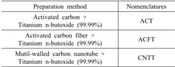
Table 1. Nomenclatures of carbon‐TiO2 composites prepared by different carbon sources and titanium n‐butoxide
Preparation method Nomenclatures Activated carbon +
Titanium n-butoxide (99.99%) ACT Activated carbon fiber +
Titanium n-butoxide (99.99%) ACFT Mutil-walled carbon nanotube +
Titanium n-butoxide (99.99%) CNTT
ACF powder and oxidized MWCNT were put into the TNB solution, respectively. At the same time, the mixtures were stirred with a magnet in a container for 5 h at 343 K. The mixtures were kept at room temperature until it formed uni- form suspension. After thermally treating at 873 K for 1 h with a heating rate of 279 K/min, the TNB in the mixture would change to TiO2, and consequence the carbon-TiO2 com- posites were obtained. The preparation condition and code of samples were listed in Table 1.
3. Characterization
Synthesized carbon-TiO2 composites were characterized by various techniques. SEM and TEM were used to observe the surface state and structure of the carbon-TiO2 composites were carried out by using a JSM-5200 JOEL electron microscope (Japan). The Brunauer-Emett-Teller (BET) surface area of the carbon-TiO2 composites was measured using a Quantachrome Surface Area analyzer (MONOSORB, USA). XRD was used for crystal phase identification and estimation of the anas- tase-to-rutile ratio. XRD patterns were obtained at room tem- perature with a meter Shimata XD-D1 (Japan) using CuKα radiation. EDX was used to measure the elemental analysis of the carbon-TiO2 composites. UV-vis spectra for the MB solution obtained from degradation by carbon-TiO2 composites dispersion under UV ray irradiation were recorded using a Genspec Ⅲ (Hitachi, Japan) spectrometer.
4. Photocatalytic decomposition
The photocatalytic effect of carbon-TiO2 composites was determined using MB decomposition in aqueous solution under an ultraviolet (UV) lamp (356 nm, 1.2 mW/cm2). The initial MB concentration was 1.0×10⁻⁵ mol/L (c0). The amount of suspended composites was kept at 1 g/L in 50 mL MB solution. Before turning on UV lamp, the solution mixed with composites was kept in the dark for at least 2 h, allowing the adsorption-desorption equilibrium to be reached. Then, the solution was irradiated with UV. The first sample was taken out at the end of the dark adsorption period (just before the
AC
TiO
2
ACF TiO
2(a) (b)
CNT TiO
2(c) (d)
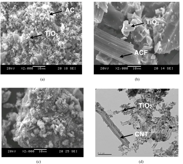
Figure 1. SEM images of the carbon‐TiO2 composites; (a) ACT, (b) ACFT, (c) CNTT and (d) TEM image of the sample CNTT.
light was turned on), in order to determine the MB concen- tration in solution, which was hereafter considered as the initial concentration (cads) after dark adsorption. Samples were then withdrawn regularly from the reactor by an order of 30 min, 90 min, 120 min and 300 min, and immediately centrifuged to separate any suspended solid. The clean transparent solution was analyzed by using a UV-vis spectrophotometer (250~600 nm). The spectra (550-750 nm) for each sample were recorded and the absorbance was determined at characteristic wave- length 660 nm for the each MB solution degraded.
Ⅲ. Results and Discussion
1. Characteristics of carbon-TiO2 composites
Morphology of carbon-TiO2 composites prepared from differ- ent carbon sources with TNB is characterized by SEM and
TEM. The SEM images of the carbon-TiO2 composites are shown in Figure 1. In the case of sample ACT (Figure 1 a), the TiO2 particles are mixed with AC very well and distributed regularly on the surface of AC with small aggregation. The morphology of sample ACFT is observed in Figure 1 (b). It is clear that the particles of TiO2 aggregated into clusters and are fixed on the surface of ACF. As shown in Figure 1 (c), the sample CNTT is an irregular aggregate of particles with large amount of TiO2 particles and small amount of CNT particles. And the MWCNTs are embedded into TiO2 particle aggregates. Furthermore, the TEM image in Figure 1 (d) con- firms the more detailed morphology of sample CNTT. It is cleanly seen that TiO2 particles are coated on the surface of MWCNT irregularly with some agglomeration.
The results of BET surface area of pristine AC, ACF, MWCNT and carbon-TiO2 composites prepared from different carbon sources with TNB are shown in Table 2. The BET
Table 2. The BET surface area of carbon‐TiO2 composites pre- pared by different carbon sources and titanium n‐butoxide
Samples SBET (m2/g)
As-received AC 1083
As-received ACF 1842
As-received MWCNT 232
ACT 728
ACFT 978
CNTT 84
10 20 30 40 50 60 70 80
-200 0 200 400 600 800 1000 1200 1400 1600 1800 2000 2200 2400 2600 2800 3000
CNTT ACFT
Intensity (Counts)
2-Theta (o)
ACT
Figure 2. XRD patterns of carbon‐TiO2 composites prepared by different carbon sources and titanium n‐butoxide.
surface area of pristine AC, ACF and pristine MWCNT is 1083 m2/g, 1842 m2/g and 232 m2/g, respectively. Comparing with these pristine materials, it can be clearly seen that there is a markedly decrease of BET surface area after pristine AC, ACF and pristine MWCNT reacting with TNB, which is 728 m2/g, 978 m2/g and 84 m2/g, respectively. As the TNB is sol- ution, so it can be reacted with carbon sources very well and introduced the pore of carbon sources easily. Moreover, the TiO2 particles which coated on the surface of carbon sources are agglomerated together thus decreased the BET surface area.
Figure 2 shows typical XRD patterns of carbon-TiO2 com- posites prepared from different carbon sources with TNB. As we know,18-20 the anatase phase formed below 773 K starts to transform to rutile-type structure above 873 K and changed into single phase of rutile at 973 K-1173 K, the crystal struc- ture of the titanium dioxide is mainly determined by the heat treatment temperature, and the peaks at 25.3, 37.8, 48.0 and 62.5 are the diffractions of (101), (004), (200) and (204) planes of anatase, the peaks at 27.4, 36.1, 41.2 and 54.3 belong to the diffraction peaks of (110), (101), (111) and (211) of rutile.
In this present case, all of the composites are heat-treated at
873 K for 1 h and have peaks at 25.3, 37.8, 48.0, 53.8, 54.9 and 62.5 are the diffractions of (101), (004), (200), (105), (211) and (204) planes of anatase without any other peaks at 27.4, 36.1, 41.2 and 54.3 belong to the diffraction peaks of (110), (101), (111) and (211) of rutile, indicating all of the composites only existed in an anatase state. On the other hand, the charac-
(a)
(b)
(c)
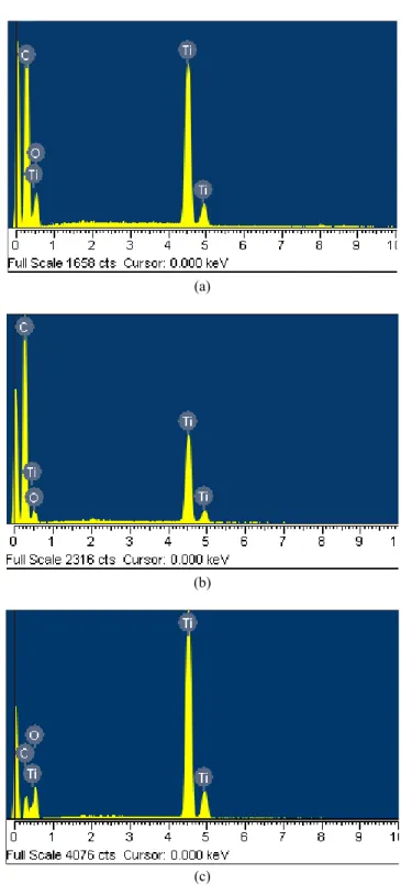
Figure 3. EDX microanalyses of the carbon‐TiO2 composites;
(a) ACT, (b) ACFT and (c) CNTT.
Table 3. EDX elemental microanalysis (wt. %) of carbon‐TiO2
composites prepared by different carbon sources and titanium n‐butoxide
Samples Elements
C O Ti
ACT 51.91 20.72 27.37
ACFT 40.70 27.42 31.56
CNTT 22.51 37.17 40.32
teristic peaks of MWCNTs could hardly be identified from the XRD patterns of carbon-TiO2 composites. These high angle diffractions are complicated and not easily detected in the fig- ure because of the overlapping of diffraction peaks attributed to TiO2 and those of the MWCNTs support.
The carbon-TiO2 composites prepared from different carbon sources with TNB are characterized by EDX. The EDX spectra and EDX elemental microanalysis (wt. %) are shown in Figure 3 and Table 3. From these data, we can see that the main elements such as C, O and Ti are existed in each sample.
And the samples ACT and ACFT are richer in C element than sample CNTT, indicated that they have better adsorption effect than sample CNTT. However, the sample CNTT are richer in Ti and O elements than samples ACT and ACFT, indicated sample CNTT have better photocatalytic effect than both of samples ACT and ACFT.
2. Photocatalytic degradation of the MB solution
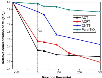
The changes in relative concentration (c/c0) of MB in the aqueous solution on time of UV irradiation for the carbon-TiO2
composites were determined and the results are shown in Figure 4. As mentioned above, before turning on UV lamp, the MB solution mixed with composites was kept in the dark for at least 2 h, allowing the adsorption-desorption equilibrium to be reached. From the Figure 4, we can see that the concen- tration of MB solution is reduced 65% and 53% after adsorp- tion by samples ACT and ACFT. However, the sample CNTT shows lowest adsorption ability for MB solution, only remove 13%. It can be explained from the data of BET surface showed above. After turning the UV lamp, the photocatalytic effect is started. The concentration of MB solution for all samples is decreased by an increasing order of UV irradiation time.
As we forecasting, the sample CNTT have most excellent pho- tocatalytic effect, which removed 30% of MB solution. The sample ACFT also has excellent photocatalytic effect, which removed 27% of MB solution. And the sample ACT has lowest photodegradation ability, which only removed 9% of MB solution. The apparent kinetic constant (kapp) of photocatalytic effect by the synthesized catalysts was also showed in Table 4.
-100 0 100 200 300
0.1 0.2 0.3 0.4 0.5 0.6 0.7 0.8 0.9 1.0
cads
Relative concentration of MB(c/c0)
Reaction time (min)
ACT ACFT CNTT Pure TiO2
Figure 4. Dependence of relative concentration of MB in the aqueous solution c/c0 on time of UV irradiation for the pure TiO2 and carbon‐TiO2 composites prepared by different carbon sources and titanium n‐butoxide; the concentration of MB sol- ution: 1.0×10‐5 mol/L.
Table 4. Apparent kinetic constant (kapp) of pure TiO2 and car- bon‐TiO2 composites prepared by different carbon sources and titanium n‐butoxide
Samples kapp (min-1)
ACT 9.6×10⁻⁴
ACFT 1.98×10⁻³
CNTT 2×10⁻³
Pure TiO2 3.14×10⁻⁴
The samples ACFT and CNTT gave the apparent constant of 1.98×10⁻³ min-1 and 2.0×10⁻³ min-1, respectively. However, comparing the samples ACFT and CNTT, the sample ACT gave much lower apparent kinetic constant, which is only 9.6×10⁻⁴ min-1. But it is even higher than pure TiO2 (3.14×10⁻⁴ min-1). It can be indicated that the samples ACFT and CNTT have much more photocatalytic activity than sample ACT.
According to our previous works,20,21,29 the degradation of MB solution for carbon-TiO2 composites may have several effects. Firstly, adsorption effect, because the AC, ACF and MWCNT have large surface areas and different aperture struc- ture, can adsorb oxygen and MB particles in solution on the inside or outside of the surface. Secondly, photocatalytic ef- fect, the TiO2 has excellent photocatalytic effect under the UV irradiation. Furthermore, the carbon sources can also adsorb the photo-induced electron (e-) by UV irradiation. Oxygen will get electron from MWCNTs to form very reactive superoxide radical ion O2·-, which not only enhances oxidation ability but also absorbs electron on the surface of carbon sources. Thus the photocatalytic activities can be strongly improved. In this
study, we used AC, ACF and MWCNT as carbon sources which have different structures. From the SEM images, we can observe that AC is formed by powder structure, ACF is formed by column structure, and MWCNT is formed by tube structure. It can be considered that the column structure and tube structure could adsorb the photo-induced electron (e-) by UV irradiation more strongly, due to they have much bigger surface area to adsorp the UV light than powder structure.
In conclusion, the sample ACFT has best degradation of MB solution.
Ⅳ. Conclusions
The carbon-TiO2 composites were prepared from AC, ACF and MWCNT with titanium n-butoxide. By the SEM and TEM observations, the TiO2 particles were coated on the surface of carbon sources and with some aggregations. There is a markedly decrease of BET surface area after carbon sources reacting with TNB, and the samples ACT and ACFT have large BET surface area. XRD results were indicating all of the composites only existed in an anatase state. From the EDX data, the main elements such as C, O and Ti were existed.
Finally, according to the results of MB degradation experi- ment, we could see that sample ACFT had most excellent deg- radation of MB solution. And the degradation of MB solution for carbon-TiO2 composites could be considered by adsorption effect of carbon sources and photocatalytic effect of TiO2. Furthermore, carbon sources could also adsorb the photo-in- duced electron (e-) by UV irradiation, which could be strongely improved the photocatalytic activities.
References
1. K.E. Coulter and A.G. Sault, “Effects of activation on the surface properties of silica-supported cobalt catalysts”, J.
Catal., 154, 56 (1995).
2. T. Wakanabe, A. Kitamura, E. Kojima, C. Nakayama, K.
Hashimoto, A. Fuijishima, in: D.E. Olis, H. Al-Ekabi (Eds.),
“Photocatalytic Purification and Treatment of Water and Air”, Elsevier, Amsterdam, 1993, p. 747.
3. A.M. Tonejc, M. Goti, B. Grzeta, S. Music, S. Popovi, R.
Trojko, A. Turkovi, and I. MuSevic, “Transmission electron microscopy studies of nanophase TiO2”, Mater. Sci. Eng. B, 40, 177 (1996).
4. E. Traversa, G. Gnappi, A. Montenero, and G. Gusmano,
“Ceramic thin films by sol-gel processing as novel materials for integrated humidity sensors”, Sens. Actuators B, 31, 59 (1996).
5. B. Ohtani and S. Nishimoto, “Effect of surface adsorptions of aliphaticalcohols and silver ion on the photocatalytic activ- ity of TiO2 suspended in aqueous-solutions”, J. Phys. Chem., 97, 920 (1993).
6. K. Fukushima and I. Yamada, “Electrical properties of TiO2
films deposited by a reactive-ionized cluster beam”, J. Appl.
Phys., 65, 619 (1989).
7. B. O’Regan and M. Gratzel, “A low-cost, high-efficiency so- lar cell based on dye-sensitized colloidal TiO2 films”, Nature, 353, 737 (1991).
8. Y.J. Liu and R.O. Claus, “Blue light emitting nanosized TiO2
colloids”, J. Am. Chem., 119, 5273 (1997).
9. J. Matos, J. Laine and J.M. Herrman, “Effect of the type of activated carbons on the photocatalytic degradation of aqueous organic pollutants by UV-irradiated titania”, J.
Catal., 200, 10 (2001).
10. B. Tryba, A.W. Morawski, and M. Inagaki, “Application of TiO2-mounted activated carbon to the removal of phenol from water”, Appl. Catal. B, 41, 427 (2003).
11. C.H. Ao and S.C. Lee, “Enhancement effect of TiO2 immobi- lized on activated carbon filter for the photodegradation of pollutants at typical indoor air level”, Appl. Catal. B, 44, 191 (2003).
12. Y.C. Chiang and C.P. Huang, “Effects of pore structure and temperature on VOC adsorption on activated carbon”, Carbon, 39, 523 (2001).
13. M. Inagaki, Y. Hirose, T. Matsunaga, T. Tsumura, and M.
Toyoda, “Carbon coating of anatase-type TiO2 through their precipitation in PVA aqueous solution”, Carbon, 41, 2619 (2003).
14. G.M. Colon, C. Hidalgo, and M. Macias, “Enhancement of TiO2/C photocatalytic activity by Sulfate Promotion”, Appl.
Catal. A, 259, 235 (2004).
15. M.C. Lu and J.N. Chen, “Effect of adsorbents coated with titanium dioxide on the photocatalytic degradation of propox- ur”, Chemosphere, 38, 617 (1999).
16. J. Arana and J.M. Dona, “TiO2 activation by using activated carbon as a support part I. surface characterisation and decant- ability study”, Appl. Catal. B, 44, 161 (2003).
17. S.X. Liu, X.Y. Chen, and X. Chen, “A TiO2/AC composite photocatalyst with high activity and easy separation prepared by a hydrothermal method”, J. Hazard. Mater., 143, 257 (2007).
18. W.C. Oh, M.L. Chen, and C.S. Lim, “Preparation with differ- ent mixing ratios of anatase to activated carbon and their pho- tocatalytic performance”, J. Cera. Process. Res., 8, 119 (2007).
19. W.C. Oh, J.S. Bae, M.L. Chen, and Y.S. Ko, “Characterisation of composite prepared with different mixing ratio of TiO2
to activity carbon and their photocatalytic activity”, Analy.
Sci. Technol., 19, 376 (2006).
20. W.C. Oh, J.S. Bae, and M.L. Chen, “Characterisation of AC/TiO2 composite prepared with pitch binder and their pho- tocatalytic activity”, Bull. Korean Chem. Soc., 27, 1423 (2006).
21. W.C. Oh and M.L. Chen, “Electrochemical preparation of TiO2/ACF composites with TNB electrolyte and their photo-
catalytic effect”, J. Ceram. Process. Res., 9, 100 (2008).
22. P. Le Cloirec, C. Brasquet, and E. Subrenat, “Adsorption onto fibrous activated carbon: applications to water treatment”, Energy Fuels, 11, 331 (1997).
23. S. Iijima, “Helical microtubeles of graphitic carbon”, Nature, 354, 56 (1991).
24. A. Jitianu, T. Cacciaguerra, R. Benoit, S. Delpeux, F. Beguin, and S. Bonnamy, “Synthesis and characterization of carbon nanotubes-TiO2 nanocomposites”, Carbon, 42, 1147 (2004).
25. W.C. Oh and M.L. Chen, “Synthesis and characterization of CNT/TiO2 composites thermally derived from MWCNT and titanium(Ⅳ) n-butoxide”, Bull. Korean Chem. Soc., 29, 159 (2008).
26. M.L. Chen and W.C. Oh, “Preparation and photocatalytic ef
fect of MWCNT/TiO2 composites”, Analy. Sci. Technol., 21, 229 (2008).
27. M.L. Chen, F.J. Zhang, and W.C. Oh, “Photocatalytic degra- dation of methylene blue by CNT/TiO2 composites prepared from MWCNT and titanium n-butoxide with benzene”, Journal of the Korean Ceramic Society, 45, 651 (2008).
28. M.L. Chen, F.J. Zhang, and W.C. Oh, “Preparation and photo- catalytic degradation of CNT/TiO2 composites using MWCNT and various titanium alkoxide precursors”, Analy. Sci.
Technol., 21, 553 (2008).
29. M.L. Chen, F.J. Zhang, and W.C. Oh, “Synthesis, character- ization, and photocatalytic analysis of CNT/TiO2 composites derived from MWCNTs and titanium sources”, New Carbon Materials, 24, 159 (2009).