에 관한 차원 유한요소 분석적 연구 Kimplant 3
서울대학교 치과대학 보철학교실 김우영 장경수 김창회 김영수․ ․ ․
Three Dim ensional Finite Elem ent Analysis of Kim plant
Woo-Uoung Kim, Kyung-Soo Jang, Chang-Whe Kim, Yung-Soo Kim
Department of Prosthodontics, College of Dentistry, Seoul National University
In this study, the biomechanical characteristics of Kimplant were compared with that of Brånemark implant by using three dimensional finite element analysis.
Two finite element models were fabricated by inserting each implant into the bone model. The bone model was designed to have 18mm height, 13mm width and 15mm length. The size of each implant was planned to have 4mm width and 10mm length. A 200N force was applied on the center of abutment top in three directions - vertical, horizontal and oblique. After analyzing the stresses of fixture and surrounding bone, following results were obtained.
1. There was similar stress distribution between the two models.
2. The magnitude of maximum principal stress on the implant was similar between the two models but the location of maximum principal stress on the implant was different.
3. The magnitude and location of maximum principal stress on the surrounding bone was similar between the two models.
K ey words : Kimplant, finite element analysis, implant design
Ⅰ 서. 론
지난 30여년간 골유착 현상을 이용한 치과 임플 랜트는 성공적으로 사용되어 왔고 발전을 거듭하, 였다 근래에는 골유착 자체의 성공여부에 대한 관. 심을 넘어서 빠르고 쉽고 안정적인 결과를 얻고자, , 노력하고 있다.1-9)
임플랜트의 성공에 관여하는 요소는 여러 가지를 들 수 있다 임플랜트 재료의 생체 적합성 임플랜. , 트의 표면형태 식립한 부위의 골조직의 양과 질, , 외상을 최소화 하는 부드럽고 정교한 외과적 술식, 적절한 하중 분담을 이루어 낼 수 있는 보철물 설계 등이 있다 이중에서 임플랜트 표면의 거시적 미시. , 적 형태는 세포수준의 골조직 치유과정 나아가 골, 유착 과정에 영향을 미치는 것으로 알려져 있다.
는 서울대학교 치과대학 보철학교실의 김 Kimplant
영수 교수님께서 개발하신 임플랜트로서 현재 임상 과 실험실에서 제한적으로 사용되고 있다 거시적.
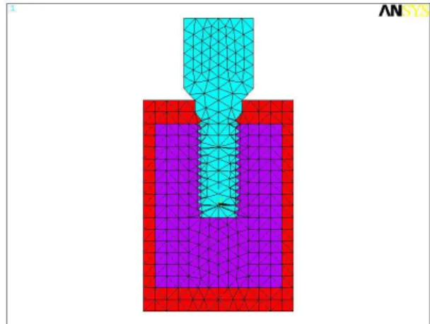
Fig. 1. Cross section of Brånemark implant model.
형태는external hex형의 상단부를 가진 나선형 임플 랜트이다 각 나선의 상면은 임플랜트 장축에 수직. 이고 나선의 하면은 상방으로, 45도 경사진 형태를 가지고 있으며 임플랜트의 근단부가 반원형으로 만 곡된 특징적인 형태를 가지고 있다 미시적으로는.
처리된 거친 표면을 가지고 있다
RBM .
본 연구에서는Kimplant와Brånemark 임플랜트에 대한 차원 유한요소 분석을 통해 거시적 형태에3 대한 생역학적인 특징을 비교 관찰하고자 하였다.
Ⅱ 연구재료 및 방법. 차원 유한요소모형 제작 1. 3
유한요소모형 설계용 소프트웨어인 I-DEAS (master series version 8.0, Structural Dynamics Research 를 이용하여 Corporation, Milford, Ohio, U.S.A.)
상에서 차원 유한요소모형을 설계하였 Pentium PC 3
다.
Fig. 2. Cross section of Kimplant model.
에 관한 차원 유한요소 분석적 연구 Kimplant 3
서울대학교 치과대학 보철학교실 김우영 장경수 김창회 김영수․ ․ ․
에는2mm,측면에는1mm가 되도록 하였다 임플랜. 트는 직경4mm, 길이 10mm로 설정하였고 지대주, 가 부착된 형태를 갖도록 하였다 임플랜트 식립 깊. 이는 고정체와 지대주의 연결부위가 골조직의 상면 에 일치되도록 하였다.
모형은 Brånemark 임플랜트를 식립한 것과 를 식립한 개를 제작하였다
Kimplant 2 .(Fig.1,2) 완성된 모형의 절점과 요소수는 Table 1과 같다.
물성치 및 경계조건 2.
실험에 사용된 재료의 물성치는 선현들의 연구를 참고로 하여 표와 같이 부여하였다.10-14)(Table 2) 모 든 재료는 균질성(homogeneity), 등방성(isotropy),선 탄성(linear elasticity)을 가지고 각 재료의 계면은 완 전한 결합상태인 것으로 가정하였다.
골조직 모형의 하면은 모든 방향에 대해서 자유 도가 고정된 것으로 하였고 측면은 수직방향으로, 의 변위만 고정되도록 경계조건을 지정하였다.
3. 하중조건
하중은 지대주 상면의 중앙에 가하였다 하중은. 교합력 분석자료를 토대로 200N의 하중15) 을 선택
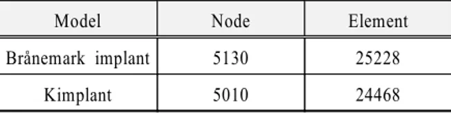
Table 1. Nodes and elements of each model.
Model Node Element
Brånemark implant 5130 25228
Kimplant 5010 24468
Table 2. Young's modulus and Poisson's ratio of some materials.
Young's modulus
(GPa) Poisson's ratio
Titanium 103.4 0.35
Cortical bone 13.7 0.30
Cancellous bone 1.37 0.30
해석은 ANSYS (Ver. 5.3, Swanson Analysis 유한요소분석 프로그 System Incorporation, U.S.A.)
램을 이용하여 시행하였다.
해석결과의 평가는 임플랜트와 골조직에 대한 최 대 주응력과 응력분포를 관찰 대상으로 하였다.
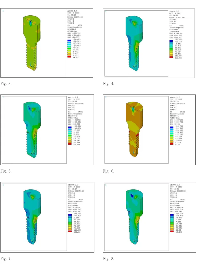
Ⅲ 결. 과 고정체에 대한 최대주응력 1.
수직하중에 대해 Brånemark 임플랜트의 경우 의 최대압축응력과 의 최대인장응 35.8MPa 9.5MPa
력을, Kimplant의 경우 39.1MPa의 최대압축응력과 의 최대인장응력을 나타내었다 최대압축응
7.0MPa .
력은 힘이 작용된 주위에서 나타났고 최대인장응, 력은 Brånemark 임플랜트의 경우 근단부에서, 의 경우 첫번째 나선주위에서 관찰되었다
Kimplant .
수평하중에 대해 Brånemark 임플랜트의 경우 의 최대압축응력과 의 최대인장응 25.5MPa 110.0MPa
력을, Kimplant의 경우 25.5MPa의 최대압축응력과 의 최대인장응력을 나타내었다 최대압축
114.0MPa .
응력은 Brånemark 임플랜트의 경우 원심부 번째2 나선 근처에서, Kimplant의 경우 원심부 첫번째 나 선주위에서 관찰되었다 최대인장응력은. Brånemark 임플랜트와Kimplant 모두 근심부 첫번째 나선주위 에서 관찰되었다.
경사하중에 대해 Brånemark 임플랜트의 경우 의 최대압축응력과 의 최대인장응 31.0MPa 41.9MPa
력을, Kimplant의 경우 33.8MPa의 최대압축응력과 의 최대인장응력을 나타내었다 최대압축
43.0MPa .
응력은 Brånemark 임플랜트의 경우 원심부 번째2 나선 근처에서, Kimplant의 경우 원심부 고정체와 지대주 경계부위에서 관찰되었다 최대인장응력은. 임플랜트와 모두 근심부 첫번 Brånemark Kimplant
째 나선주위에서 관찰되었다.
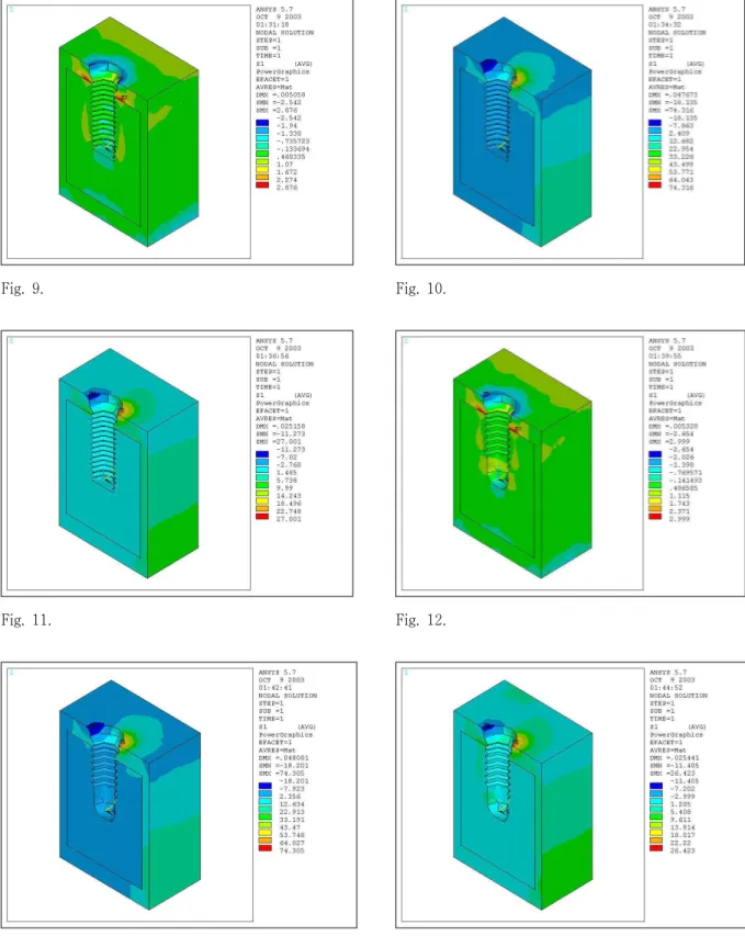
주변골에 대한 최대주응력 2.
수직하중에 대해 Brånemark 임플랜트의 경우 의 최대압축응력과 의 최대인장응력 2.0MPa 1.5MPa
을, Kimplant의 경우 2.1MPa의 최대압축응력과 의 최대인장응력을 나타내었다 최대압축응
1.7MPa .
력은 Brånemark 임플랜트와 Kimplant 모두 피질골 상연에서 관찰되었고 최대인장응력은 Brånemark 임플랜트와Kimplant 모두 피질골과 해면골의 경계 부위에서 관찰되었다.
수평하중에 대해 Brånemark 임플랜트의 경우 의 최대압축응력과 의 최대인장응 15.9MPa 62.8MPa
력을, Kimplant의 경우 15.9MPa의 최대압축응력과 의 최대인장응력을 나타내었다 최대압축
63.1MPa .
응력은 Brånemark 임플랜트와 Kimplant 모두 피질 골 상연 원심부에서 관찰되었고 최대인장응력은 임플랜트와 모두 피질골 상연 Brånemark Kimplant
근심부에서 관찰되었다.
경사하중에 대해 Brånemark 임플랜트의 경우 의 최대압축응력과 의 최대인장응 9.7MPa 22.9MPa
력을, Kimplant의 경우 9.8MPa의 최대압축응력과 의 최대인장응력을 나타내었다 최대압축
22.5MPa .
응력은 Brånemark 임플랜트와 Kimplant 모두 피질 골 상연 원심부에서 관찰되었고 최대인장응력은 임플랜트와 모두 피질골 상연 Brånemark Kimplant
근심부에서 관찰되었다.
Ⅳ 총괄 및 고안.
임플랜트 디자인은 임플랜트 식립시의 초기 안정 성과 관련이 있을 뿐 아니라 임플랜트와 골조직간 의 계면에 교합력이 전달되는 양상에도 영향을 줄 수 있다 거시적으로 볼 때 임플랜트의 외형 직경. , , 길이 나선의 형태 등이 임플랜트 디자인과 관련되,
어 있다.
임플랜트의 길이가 길어질수록 임플랜트의 초기 안정성을 높일 수 있고 전체 임플랜트 골조직 계면, - 을 증가시킬 수 있어서 응력분산에 유리하다고 알 려져 있다 또한 짧은 길이의 임플랜트에서 낮은 성. 공률을 보였다는 임상 연구 보고도 다수 접할 수 있
다.16-21) 그러나Lum등22)의 정역학 연구 결과에 의하
면 임플랜트의 길이가 12mm 이상이 되면 길이가 증가한 만큼의 응력 감소 효과는 없다고 보고한 바 있다 그리고. Bruggenkate등23)이 6mm의 짧은 ITI 임 플랜틀를 식립한 후 년 뒤에 평가한 결과 누적생6 존율이 94% 이었다고 보고하면서 골질이 나쁘지 않은 경우에는 짧은 임플랜트의 사용도 가능함을 주장한 바 있다.
임플랜트 직경이 증가하게 되면 임플랜트의 둘레 길이가 길어지게 되고 따라서 골조직과의 접촉 면 적이 증가하게 된다 임플랜트의 길이 증가가 치조. 골능 부위에서의 응력 감소 효과는 크지 않은 반면, 임플랜트의 직경을 증가시키면 치조골능 부위의 응 력을 감소 시킬 수 있다 임플랜트를 통해 교합력이. 작용될 경우 대부분의 응력이 치조골능 주위에 집 중된다는 점을 고려해 볼 때 임플랜트의 직경은 더 중요한 의미를 가진다고 볼 수 있다.22)
임플랜트 나선은 초기고정을 증가시키고 접촉면, 적을 넓혀 주며 임플랜트와 골조직간의 계면에서, 응력을 분산시켜 주는 역할을 한다 나선의 깊이. , 두께 각도 나선간의 거리 나선의 회전각도 등이, , , 생역학적으로 영향을 주게 된다 현재. V자형 사각, 형, buttress형 등의 나선 형태를 가진 제품을 접할 수 있는데 각각의 형태에 대해 주장되는 차이는 있, Table 3. Maximum principal stress of implant and surrounding bone.
Bone (Mpa) Implant (Mpa)
Compressive Tensile Compressive Tensile
Brånemark implant
Vertical -2.0276 1.5426 -35.846 9.4541
Horizontal -15.855 62.815 -25.453 109.99
Oblique -9.6841 22.886 -31.043 41.884
Kimplant
Vertical -2.1080 1.6612 -39.054 7.0010
Horizontal -15.924 63.092 -25.513 113.99
Oblique -9.7886 22.518 -33.822 42.993
임플랜트와 는 모두 나선형 Brånemark Kimplant
임플랜트로써 근단부의 모양 나선의 수와 위치 나, , 선의 모양에 있어서 외형적인 차이를 보이고 있다.
는 근단부가 둥근 형태를 가지고 있으며
Kimplant ,
근단1/3부위에는 나선이 형성되어 있지 않다 나선. 간의 간격도 약간 넓으며 나선의 형태는 각 나선의, 상면이 임플랜트 장축에 수직이고 나선의 하면은 상방으로 45° 경사진 삼각형 형태의 모양을 갖고 있다 이러한 구조는 유한요소 분석을 통해 다른 형. 태보다 작은 응력을 보이는 것으로 알려져 있다.24) 본 실험에서는 유한요소 분석법을 이용하여 임플랜트와 를 비교하고자 하였 Brånemark Kimplant
다 그러나 이 실험은 실제 임상에서 접하는 상황과. 는 다소 차이가 있음을 고려하여야 한다 여기에서. 설계한 골조직은 충분한 폭경과 높이를 가지고 있 다 따라서 임플랜트는 대부분 해면골에 식립되어. 있고 단지 임플랜트의 치경부에서만 피질골과 접하 고 있다 그러나 실제 임상에서 접하는 골조직은 다. 양한 폭경과 골질을 보이고 있어서 임플랜트가 피 질골과 접하는 양상이 다양하게 나타날 것이다 이. 러한 상황에서의 응력 분포는 다소 차이를 보일 것 으로 예견된다.
본 연구에서는 골조직 임플랜트 계면이 완전히- 접촉한다고 가정하였다 또한 임플랜트 고정체와. 지대주를 편의상 일체된 형태로 설계하였는데 이, 러한 면도 실제와는 다른 상황이라고 볼 수 있다.
이 외에도 많은 부분이 실제 임상에서 접하는 상황 과는 다른 면을 가지고 있다 그러나 여러 상황을. 단순화하여 필요한 부분만을 비교 평가하고자 하는 것이 본 연구의 궁극적인 목적이라고 할 수 있다.
실험결과 두 임플랜트에 작용된 최대주응력은 거, 의 유사하였고 단지 응력 분포에 있어서 약간의 차, 이를 보이고 있었다 대체로. Kimplant에서 좀 더 치 관쪽에 최대주응력이 분포되어 있었다 그러나 최. 대주응력 분포위치의 차이가 크게 나타나지는 않았 다 이 결과는 원등. 25)의 토끼를 대상으로 한 동물실 험 결과와도 관련이 있다고 볼 수 있다 원등은. 와 형태의 임플랜트에 대해 공진 Kimplant Brånemark
주파수 분석과 회전제거력 실험을 한 결과 두 임플 랜트간에 유의할 만한 차이가 관찰되지 않았다고
사용되고 있는데 좀 더 많은 연구결과가 발표될 것 으로 기대하고 있다 또한 향후 장기적인 임상연구. 를 통해 Kimplant의 예후 관찰이 필요하리라 사료 된다.
V. 결 론
와 임플랜트의 응력분포는 유 1. Kimplant Brånemark
사한 양상을 보였다.
고정체에 대한 최대주응력의 크기는 두 임플랜 2.
트간에 차이가 관찰되지 않았으나 최대주응력이 나타나는 부위는 차이가 관찰되었다.
주변골에 대한 최대주응력의 크기와 최대주응력 3.
이 나타나는 부위는 두 임플랜트간에 차이가 관 찰되지 않았다.
참 고 문 헌
1. Ericsson I, Randow K, Glantz P-O, Lindhe J, Nilner K.
Clinical and radiographical features of submerged and non-submerged titanium implants. Clin Oral Impl Res 1994;5:185-189.
2. Ericsson I, Randow K, Nilner K, Petersson A. Some clinical and radiographical features of submerged and non-submerged titanium implants. A 5-year follow-up study. Clin Oral Impl Res 1997;8:422-426.
3. Becker W, Becker BE, Israelson H, et al. One-step surgical placement of Brånemark implants: a prospective clinical multicenter study. Int J Oral Maxillofac Implants 1997;12:454-462.
4. Collaert B, deBruyn H. Comparison of Brånemark fixture integration and short-term survival using one-stage or two-stage surgery in completely and partially edentulous mandibles. Clin Oral Impl Res 1998;9:131-135.
5. Schnitman PA, Whörle PS, Rubenstein JE. Immediate fixed interim prostheses supported by two-stage threaded implants: methodology and results. J Oral Implantol 1990;16:96-105.
6. Schnitman PA, Whörle PS, Rubenstein JE, Silva JD, Want NH. Ten-year results for Brånemark implants loaded with fixed prostheses at fixture placement. Int J Oral Maxillofac Implants 1997;12:495-503.
7. Henry PJ, Rosenberg I. Single-stage surgery for rehabilitation of the edentulous mandible. Preliminary results. Pract Periodont Aesthetic Dent 1994;6:1-9.
8. Balshi TJ, Wolfinger GJ. Immediate loading of Brånemark implants in edentulous mandibles: a preliminary report. Implant Dent 1997;6:83-88.
9. Randow K, Ericsson I, Nilner K, Petersson A, Glantz P-O. Immediate functional loading of Brånemark dental implants. An 18-month study. Clin Oral Impl Res 1999;10:8-15.
10. Meijer HJA, Starmans FJM, Bosman F, Steen WHA. A comparison of three finite element models of an edentulous mandible provided with implants. J Oral Rehabil 1993;20:147-157.
11. Lee JM, Kim YS, Kim CW, Kim YH. 3-D FEA of three different single tooth abutments: cement-retained vs screw-retained. J Korean Acad Prosthodont 1999;37(2):269-280.
12. Van Rossen, I.P. Stress-absorbing element in dental implants. J Prosthet Dent 1990;64:198-205.
13. Katona TR, Winkler MM. Stress analysis of a bulk-filled clV light-cured composite restoration. J Dent Res 1994;73(8):1470-1477.
14. Jang KS, Kim YS, Kim CW. Three dimensional finite element analysis on the minimum contact fraction of bone-implant interface. J Korean Acad Prosthodont 1997;35(4):627-640.
15. Haraldson T, Carlsson GE. Bite force and oral function in patients with osseointegrated oral implants. Scand J Dent Res 1977;85:200-208.
16. Bahat O. Treatment planning and placement of implants in the posterior maxillae: report of 732 consecutive Nobelpharma implants. Int J Oral Maxillofac Implants.
1993;8:151-161.
17. Buser D, Mericske-Stern R, Bermard JP, et al.
Long-term evaluation of non-submerged ITI implants.
Part 1: 8-year life table analysis of a prospective multi-center study with 2359 implants. Clin Oral Implants Res. 1997;8:161-172.
18. Quirynen M, Naert I, van Steenberghe D, et al. The cumulative failure rate of the Brånemark system in the overdenture, the fixed partial, and the fixed full prosthesis design: A prospective study on 1273 fixtures.
Journal of Head and Neck Pathology. 1991;10:43-53.
19. Lekholm U, van Steenberghe D, Hermann I, et al.
Osseointegrated implants in the treatment of partially edentulous patients. A prospective 5-year multicenter study. Int J Oral Maxillofac Implants. 1994;9:627-635.
20. Leckholm U, Gunne J, Henry P, et al. Survival of the Brånemark implant in partially edentulous jaws: a 10-year prospective multicenter study. Int j Oral Maxillofac Implants. 1999;14:639-645.
21. Ferrigno N, Laureti M, Fanali S, et al. A long-term follow-up study of non submerged ITI implants in the treatment of totally edentulous jaws. Part 1:ten-year life table analysis of a prospective multicenter study with 1286 implants. Clin Oral Implants Res. 2002;13:
260-273.
22. Lum LB, Osier JF. Load transfer from endosteal implants to supporting bone: an analysis using statics.
Part 1:horizontal loading. J Oral Implantol. 1992;18:
343-348.
23. ten Bruggenkate CM, Asikainen P, Foitzik C, et al.
Short (6-mm) nonsubmerged dental implants: results of a Multicenter clinical trial of 1 to 7 years. Int J Oral Maxillofac Implants. 1998;13:791-798.
24. Kim YS. 3-dimensional finite element study on surface characteristics and stress of implants. SNUDH Dept of Prosthodontics. Unpublished.
25. Won MK, Park CJ, Jang KS, et al. An experimental study of newly desinged implant with RBM surface in the rabbit tibia: resonance frequency analysis and removal torque study. J Korean Acad Prosthodont.
2003;41(6):720-731.
Fig. 3. Stress distribution of Brånemark implant under vertical force.
Fig. 4. Stress distribution of Brånemark implant under horizontal force.
Fig. 5. Stress distribution of Brånemark implant under oblique force.
Fig. 6. Stress distribution of Kimplant under vertical force.
Fig. 7. Stress distribution of Kimplant under horizontal force.
Fig. 8. Stress distribution of Kimplant under oblique force.
Fig. 9. Stress distribution of surrounding bone of Brånemark implant under vertical force.
Fig. 10. Stress distribution of surrounding bone of Brånemark implant bone under horizontal force.
Fig. 11. Stress distribution of surrounding bone of Brånemark implant under oblique force.
Fig. 12. Stress distribution of surrounding bone of Kimplant under vertical force.
Fig. 13. Stress distribution of surrounding bone of Kimplant under horizontal force.
Fig. 14. Stress distribution of surrounding bone of Kimplant under oblique force.
Fig. 3. Fig. 4.
Fig. 5. Fig. 6.
Fig. 7. Fig. 8.
Fig. 9. Fig. 10.
Fig. 11. Fig. 12.
Fig. 13. Fig. 14.