http://dx.doi.org/10.5228/KSTP.2014.23.3.139
조압연 공정의 판 폭 퍼짐 예측 모델 – Part I : 도그 본 형상에 적용
이동훈
1
· 이경보1
· 황상무#
A New Model for Predicting Width Spread in a Roughing Mill - Part I:
Application to Dog-bone Shaped Inlet Cross
D. H. Lee, K. B. Lee, S. M. Hwang
(Received October 7, 2013 / Revised January 14, 2013 / Accepted March 4, 2014)
Abstract
In the current study, we present a new model for predicting width spread of a slab with a dog-bone shaped cross section during rolling in the roughing train of a hot strip mill. The approach is based on the extremum principle for a rigid plastic material and a three dimensional admissible velocity field. The upper bound theorem is used for calculating the width spread of the slab. The prediction accuracy of the proposed model is examined through comparison with the predictions from 3-D finite element (FE) process simulations.
Key Words : Width Spread, Roughing Mill, Extremum Principle, Admissible Velocity Field, Finite Element Method, Flat
Rolling, Dog-bone
1. 서 론
근래에 압연 강판의 폭 정밀도 향상에 대한 요구 가 높아지고 있다. 폭 정도 개선은 품질 뿐만 아니 라 실수율(yielding percentage) 향상에도 크게 기여하 기 때문이다.
과거에는 최종 제품의 목표 치수가 형성되는 사 상 압연에서의 폭 퍼짐에 대한 연구가 주를 이루었 으나 최근에는 조압연에서의 슬라브(slab)의 폭 거동 에 대한 관심이 높아지는 추세이다.
조압연 공정은 사상압연과 달리 폭 압연과 수평 압 연(vertical-to-horizontal rolling)이 연속적으로 진행된다.
특히 폭 압연에 의해 슬라브의 에지부에서 국부적인 소성 변형이 발생하여 판 두께가 부풀어 오르는데 이 를 도그 본(dog-bone) 형상이라 한다. 지금까지 여러
연구자들에 의해 폭 퍼짐에 관한 모델이 제안되었으 나 대부분 평판에 대한 폭 퍼짐 모델이었고 도그 본 형상에 대한 모델은 거의 없었다[1~2].
본 연구에서는 extremum principle을 기초로 하여 근사해를 구하기 위해 새로운 가용 속도장[3~4]을 적용하였다. 본 연구에서 제시된 폭 퍼짐 예측모델 로부터 얻은 결과는 3차원 비정상상태 유한요소해 석(FE simulation)을 이용해 검증하였다.
2. 폭 퍼짐 예측 모델 수식화
2.1 Extremum principle
롤과 소재가 맞물리는 영역(bite zone)에서 일어나 는 소성 변형에 대하여 extremum principle을 적용하 면 다음과 같은 식이 된다.
1. 포항공과대학교 기계공학과
# Corresponding Author : Department of Mechanical Engineering, POSTECH, E-mail:[email protected]
Fig. 1 Definition sketch of flat rolling. Only a quadrant of the rolling geometry is shown
* * *
1 ' *
1
( )
C
lS
R
n
l
V d V V d
k V d
(1)
여기서 는 소재의 유동 응력(flow stress)를 의미 하고,
*는 유효 변형률 속도(effective strain rate), V
R은 롤 속도이다. 적용 가능한 여러 가용 속도장 (admissible velocity field) V
*가운데 실제 속도장 V 가 위의 식을 최소화한다. 또한 는 롤과 판의 접 촉면에 작용하는 마찰 응력(friction stress)이고
k 는 '최대 전단 응력(maximum shear stress)를 의미하는데 다음과 같이 나타낼 수 있다.
n (2)
' / 3
k (3)
와
n은 각각 쿨롱 마찰 계수와 수직 응력 (normal stress)를 나타낸다.
Fig. 1은 압연되는 소재의 기하학적인 개략도이다.
R 은 롤 반경을, l 은 롤과 판이 맞물리는 영역의 길이(bite length), H y
1( ) 와 H y
2( ) 는 입측과 출측의 두께의 반을 의미하며, b 는 판의 입측 반폭이다.
식 (1)의 우변의 첫 번째 항은 소성 변형에 의한 에너지를 의미하고, 두 번째 항은 마찰에 의한 에너 지를 나타낸다. 앞서 정의한 값들을 이용하면 다음 과 같이 정리할 수 있다.
,
* *
0 0 0 l b h x y
d dz dy dx
(4)
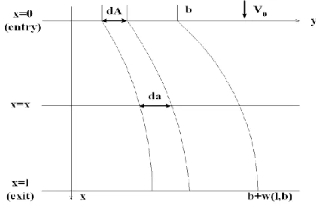
Fig. 2 Change in the width of a small element in the bite zone, lateral spread. etc
*
2
* * 2 *
0 0
cos sin
cos
C
R
l b x z R y
n
V V d
V V V V
dydx
(5)
식 (1)의 우변의 세 번째 항은 속도 불연속에 의 해 발생되는 에너지로 속도 불연속이 롤의 입측과 출측에서 발생한다고 가정하면 다음과 같이 표현된 다.
1
2
1 ' * ' * 2 * 2
0 0
1 0
2 2
' * *
0 0 lS
n b H y
y z
i x
b H y
y z
x l
k V d k V V dzdy
k V V dzdy
(6)
2.2 가용 속도장
Fig. 2는 압연 중 일어나는 소재의 폭 변동을 나 타낸 것으로 dA 는 변형 전의 미소 폭을, da 는 변 형되고 있는 상태의 미소 폭을 의미한다.
두께 방향의 변화를 무시하면 폭 방향 변위 (lateral displacement) w x y ( , ) 는 다음과 같이 정의할 수 있다.
da dA dw
dA dy
(7)
비압축성 조건을 이용하면 다음과 같은 식을 세 울 수 있다.
*
0
(0, ) ( , )
( , )
x
h y dA V x y V
h x y da
(8)
여기서 V
0는 소재의 롤 입측 속도를 의미한다.
식 (7)을 식 (8)에 대입하면 압연 진행 방향의 속도 는 다음과 같다.
* 1
0
( , ) ( ) 1
x
,
H y dw
V x y V
h x y dy
(9)
폭 방향 속도는 진행 방향 속도와 식 (10)과 같은 관계에 있다.
*
*
( , ) ( , ) ( , )
y x
V x y dw x y
V x y dx (10)
정리하면 폭 방향 속도는 다음과 같다.
*
10
( , ) ( ) 1
y
,
H y dw dw V x y V
h x y dy dx
(11)
소성 변형 중인 소재의 비압축성 조건을 이용하 면 두께방향 속도를 구할 수 있다.
* *
* x y
z
dV dV
dV
dz dx dy (12)
*
*
( , , )
zz
V x y z dV z C
dz (13)
식 (9)와 식 (11)을 식 (13)에 대입하고, 경계 조건 0
z 에서 V
z* 0 을 대입하면 두께 방향 속도는 다 음과 같이 정리할 수 있다.
1 1
0
*
2 2
1
0 2
( ) ( )
1 ( , ) ( , )
( ) ( , )
z
H y H y
dw d d dw
V dy dx h x y dy h x y dx
V z
H y d w dw d w dw V h x y dy dx dxdy dy
(14)
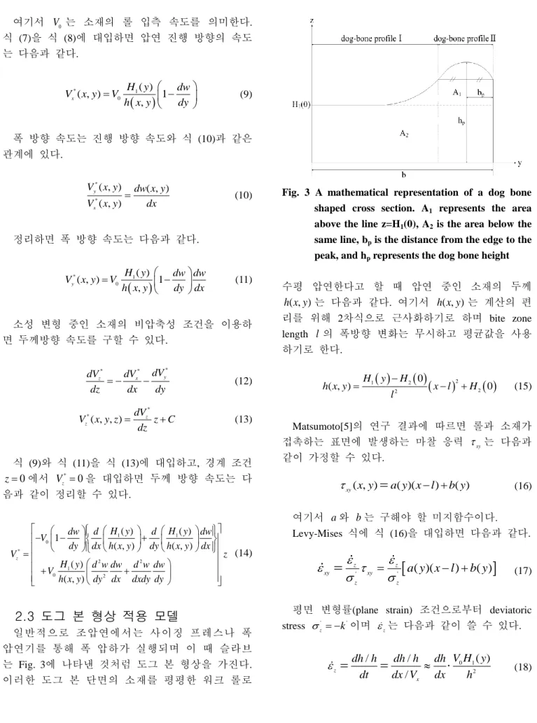
2.3 도그 본 형상 적용 모델
일반적으로 조압연에서는 사이징 프레스나 폭 압연기를 통해 폭 압하가 실행되며 이 때 슬라브 는 Fig. 3에 나타낸 것처럼 도그 본 형상을 가진다.
이러한 도그 본 단면의 소재를 평평한 워크 롤로
Fig. 3 A mathematical representation of a dog bone shaped cross section. A
1
represents the area above the line z=H1
(0), A2
is the area below the same line, bp
is the distance from the edge to the peak, and hp
represents the dog bone height수평 압연한다고 할 때 압연 중인 소재의 두께 ( , )
h x y 는 다음과 같다. 여기서 h x y ( , ) 는 계산의 편 리를 위해 2차식으로 근사화하기로 하며 bite zone length l 의 폭방향 변화는 무시하고 평균값을 사용 하기로 한다.
2
1 2
2 2
( , ) H y H 0 0
h x y x l H
l
(15)
Matsumoto[5]의 연구 결과에 따르면 롤과 소재가 접촉하는 표면에 발생하는 마찰 응력
xy는 다음과 같이 가정할 수 있다.
( , ) ( )( ) ( )
xy
x y a y x l b y
(16)
여기서 a 와 b 는 구해야 할 미지함수이다.
Levy-Mises 식에 식 (16)을 대입하면 다음과 같다.
' '
( )( ) ( )
z z
xy xy
z z
a y x l b y
(17)
평면 변형률(plane strain) 조건으로부터 deviatoric stress
'zk
'이며
z는 다음과 같이 쓸 수 있다.
0 1
2
( )
/ /
z /
x
V H y dh h dh h dh
dt dx V dx h
(18)
식 (15)를 x 에 대하여 미분한 후 식 (18)에 대입 하면
z는 다음과 같이 나타낼 수 있다.
0 1 2 1
2 2
2 0 ( )
z
V H y H H y x l
l h
(19)
y
/ V x
와 비교해서 V
x/ y 는 작은 값이므로 무 시하면
xy( , ) x y 는 다음과 같다.
1 1
( , )
2 2
y x y
xy
V V V
x y x y x
(20)
식 (17)에 식 (19), (20), (15)와
z'k
'를 대입하 고 적분하여 다음과 같이 정리할 수 있다.
0 1 2 1
' 2
4 ( ) ( )
y
( )
V H y H H y
V G y
k l
(21)
2
2
3 3 2 2
2
0
( )( ) ( )( ) ( )
1 ( ) ( )
( ) ( )
3 2
x
a y x l b y x lG y dx
h
a y b y
x l l x l l
h
(22)
1 2
0
1 1 2
3 ( ) 3
l
h hdx H y H
l
(23)
여기서 h 는 h x y
( , )의 평균값이다.
식 (21)에서 경계 조건 x l 에서 V
y 0 을 적용 하면 G y ( ) 0 을 만족해야 하는데 식 (22)에 대입 후 정리하면 다음과 같다.
( ) 2 ( ) 3
b y l
a y (24) 폭 방향 변위 w x y
( , )는 다음과 같이 정의할 수 있다.
0 0
0 1
( , )
( )
x x
y y y
x
dx h
w x y V dt V V dx
V V H y
(25)
식 (25)에 식 (21)을 대입하고 적분하여 정리하면 다음과 같이 나타낼 수 있다.
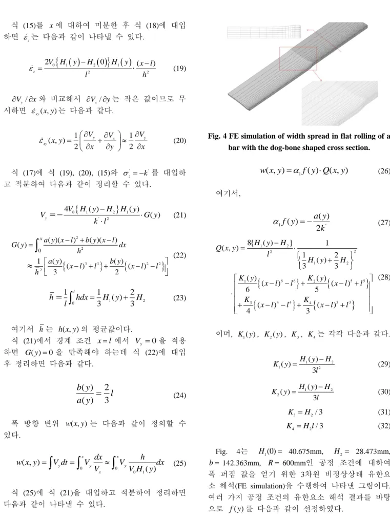
Fig. 4 FE simulation of width spread in flat rolling of a bar with the dog-bone shaped cross section.
( , )
1( ) ( , )
w x y f y Q x y (26) 여기서,
1 '
( ) ( ) 2
f y a y
k (27)
1 2
2 2
1 2
6 6 5 5
1 2
4 4 3 3
3 4
8{ ( ) } 1
( , )
1 2
3 ( ) 3
( ) ( )
( ) ( )
6 5
( ) ( )
4 3
H y H Q x y
l H y H
K y K y
x l l x l l
K K
x l l x l l
(28)
이며, K y
1( ) , K y
2( ) , K
3, K
4는 각각 다음과 같다.
1 2
1 2
( ) ( )
3 H y H
K y l
(29)
1 2
2
( ) ( )
3 H y H
K y l
(30)
3 2
/ 3
K H (31)
4 2
/ 3
K H l (32)
Fig. 4는 H
1(0) 40.675mm, H
2 28.473mm, b 142.363mm, R 600mm인 공정 조건에 대하여 폭 퍼짐 값을 얻기 위한 3차원 비정상상태 유한요 소 해석(FE simulation)을 수행하여 나타낸 그림이다.
여러 가지 공정 조건의 유한요소 해석 결과를 바탕
으로 f y
( )를 다음과 같이 선정하였다.
4 2
( ) 1 2 y y
f y b b b
(33)
3. 모델 검증 및 결과
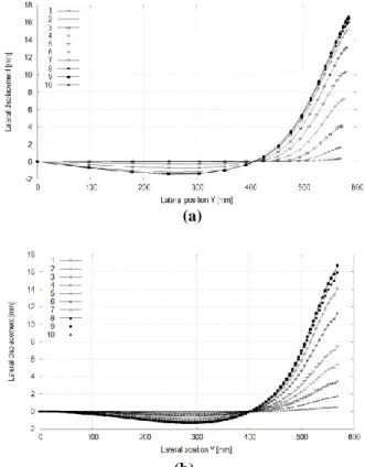
Fig. 5(a)와 (b)는 H
1(0) 62.5mm, H
2 50mm, b 570mm, R 600mm인 공정 조건에 대하여 각각 유한요소 해석과 본 연구에서 제안된 모델의 입측 에서 출측까지 bite zone 내부에서의 폭방향 변위를 나타낸 것으로, 두 결과가 잘 일치하는 것을 확인할 수 있다. 이는 여기서 선택된 f y
( )의 타당성을 입 증한다.
가용 속도장 식 (9), (11), (14)와 식 (26)을 식 (1)에 대입하고, 상계 정리(upper bound theorem)를 적용하 면 식 (1)을 최소화하는
1을 구할 수 있다. 이 때 quadratic curve fitting[9]이라는 최적화 기법을 이용하 며 이렇게 찾은
1을 통해 폭 퍼짐 양을 계산할 수 있게 된다.
Table 1에 정리한 공정 조건에 대해 이러한 일련 의 과정을 수행하여 폭 퍼짐 양을 구하고 3차원 비 정상상태 유한요소 해석을 실행하여 그 결과를 Fig.
6에 비교하였다. 대부분의 경우 유한요소 해석과 모 델의 전체 폭에 대한 폭 퍼짐의 오차 범위가 5mm 내에서 형성되는 것을 볼 수 있다.
한편, Fig. 7에 나타낸 것처럼 도그 본의 높이(dog- bone height)가 증가할수록 본 연구에서의 폭 퍼짐 모델의 예측 정밀도가 향상되는 것을 알 수 있었다.
4. 결 론
본 논문에서는 조압연 공정에서 도그 본 형상을 가지는 슬라브를 수평 압연할 때 발생하는 폭 퍼짐 을 예측하는 모델을 개발하였다. 본 연구의 폭 퍼짐 예측 모델을 구하기 위하여 extremum principle을 기반 으로 가용 속도장을 이용하였고, 유한요소 해석 결과 를 분석하여 폭방향 변위에 관한 식을 유도하였으 며 상계 정리(upper bound theorem)을 적용하여 폭 퍼 짐 양을 구했다. 다양한 공정 조건에 대하여 3차원 비정상상태 유한요소 해석을 실행했고 본 연구의 모델과 비교하여 폭 퍼짐 예측 정도를 검토하였다.
유한요소 해석과 본 연구의 모델의 오차는 5mm로
(a)
(b)
Fig. 5 (a) FEM - lateral displacements in the bite zone across the bar width. Line no. 1 indicates the lateral displacement at the roll entrance, while line no. 10 indicates the lateral displacement at the roll exit, (b) Model - lateral displacements in the bite zone across the bar width.
1 3.9627 is usedFig. 6 Width spread for the problem of a dog bone shaped inlet cross section. Comparison between predictions from the present model and those from FEM. The data represents change in the whole width (not half width) after rolling
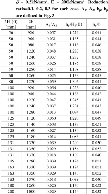
Table 1 Rolling conditions for the problem of dog bone shaped inlet cross sections. R = 600mm, V
R
= 1666.7mm/sec,
= 0.3. Regarding the flow stress and Young’s modulus of the slab material,
= 0.2kN/mm2
, E = 200kN/mm2
. Reduction ratio=0.1, 0.2, 0.3 for each case. A1
, A2
, bp
, hp
are defined in Fig. 32H 1 (0) [mm]
2b
[mm] A 1 /A 2 h p /H 1 (0) b p /b
50 920 0.057 1.279 0.041
50 960 0.031 1.185 0.044
50 980 0.017 1.118 0.046
50 1220 0.048 1.283 0.038
50 1240 0.037 1.232 0.038
50 1260 0.026 1.176 0.038
50 1280 0.014 1.108 0.038
60 1260 0.025 1.153 0.045
80 1220 0.059 1.306 0.041
100 920 0.056 1.225 0.040
100 940 0.044 1.188 0.042
100 1220 0.047 1.245 0.041
100 1240 0.037 1.201 0.043
100 1280 0.013 1.094 0.047
125 1120 0.050 1.220 0.049
125 1140 0.038 1.178 0.051
125 1160 0.027 1.134 0.052
125 1180 0.014 1.083 0.041
131 1330 0.039 1.200 0.050
131 1350 0.029 1.156 0.052
131 1370 0.018 1.109 0.040
145 1280 0.039 1.184 0.051
163 1330 0.039 1.184 0.051
163 1350 0.029 1.143 0.052
163 1370 0.018 1.099 0.040
180 1260 0.026 1.130 0.052
200 1000 0.029 1.144 0.052
양호하였고, 도그 본 높이(height)가 증가할수록 본 연구의 모델의 예측 정밀도가 향상되는 것을 확인 하였다.
본 연구의 폭 퍼짐 예측 모델에 사용된 가용 속 도장과 extremum principle은 도그 본 형상 뿐만 아 니라 평판에 대한 적용도 가능한데 이는 Part II에서 다루기로 한다.
본 연구를 통해 개발된 해석 기법과 결과는 도그 본 프로파일 예측 모델[6]과 더불어 폭 압연(edge
Fig. 7 The effect of dog-bone profile on width spread
rolling)이 폭 퍼짐에 끼치는 영향에 대한 연구와 폭 퍼짐 예측 모델 정도 향상을 위한 견고한 기초를 형성하기를 기대한다.
REFERENCES