동적 충격하중에 의한 미소균열 직조복합구조의 특성
허해규
†· 김민성
*· 정재권
*· 김용진
*Micro-Cracked Textile Composite Structures’ Behavior on the Dynamic Impact Loading
Hae-Kyu Hur, Min-Sung Kim, Jae Kwon Jung, Yong Jin Kim
Key Words : Textile-Layered Composite(직조적층 복합재), Repeating Unit Cell (반복단위격자) Abstract
This study is focused on an integrated numerical modeling enabling one to investigate the dynamic behavior and failure of 2-D textile composite and 3-D orthogonal woven composite structures weakened by micro-cracks and subjected to an impact load. The integrated numerical modeling is based on: I) determination of governing equations via a three-level hierarchy: micro-mechanical unit cell analysis, layer- wise analysis accounting for transverse strains and stresses, and structural analysis based on anisotropic plate layers, II) development of an efficient computational approach enabling one to perform transient response analyses of 2-D plain woven and 3-D orthogonal woven composite structures featuring the matrix cracking and exposed to time-dependent loads, III) determination of the structural characteristics of the textile-layered composites and their degraded features under various geometrical yarn shapes, and finally, IV) assessment of the implications of stiffness degradation on dynamic response to impact loads.
1. Introduction
To solve the problem of dynamic response of the 2-D textile and the 3-D woven textile composites, shown in Fig. 1, a thorough study of their mechanical properties and structural behavior is needed. For example, the main difficulty in the textile composite structures is the computational complexity in terms of geometry and material modeling. A review of publications on the mechanical property predictions and static response analysis of 3-D woven composites can be found in several studies1-8. These structures were also investigated in previous studies of this study. In Ref. [1], an example of multi-scale predictive analysis of 3-D woven composites exposed to static loads was presented. Some aspects of the aforementioned publication5-8 are implemented in this work for developing a dynamic analysis approach.
The approach of the damage and failure of the 2-D textile and the 3-D orthogonal woven textile composite structures under severe dynamic loads involves a number of issues of high complexity that should be addressed such as: complex damage modes in the textile composite materials; the material behavior under different strain rates, and determination of the constitutive behavior of composites in the presence of matrix cracking5, matrix and/or fiber yielding. These problems are already mentioned in Ref. [6]. It is essential to develop a computational methodology7 that may lead to an improved understanding of the impact mechanisms about the textile layered structures.
To predict the dynamic response of 2-D and 3-D woven textile composite structures featuring matrix cracking5, see Fig.2, a unit cell model of 3-D woven yarn with small infinite slit cracks of matrix regions is considered. This study assumes that a number of small slit cracks along the transverse direction, and the specific system of yarns consist of the transverse cracks and fibers. The crack can be depicted by a crack density (β ), and a crack dimension (a).
This study uses the following three hierarchal steps7: (i) unit cell micro-level (similarly to the level of static analysis Ref. [1]), (ii) homogenized warp and fill fiber
†정회원,국방과학연구소(Agency for Defense Development)
*비회원,국방과학연구소(Agency for Defense Development) E-mail: [email protected]
Tel.: (042)-821-3342
대한기계학회 2008년도 추계학술대회 논문집
ply level (thus modeling 2-D and 3-D woven composite in a layer-wise fashion, similarly to the “discrete layer”
approach in Ref.[1]), and (iii) by adopting a thick anisotropic layer, the structural model is implemented. In order to validate some results obtained within this structural model, the degradation of structural characteristics are compared with results as shown in previous literature.
Moreover, additional numerical schemes; micro- mechanical equations, the Self-Consistent method and an iterative scheme6, are applied into the three hierarchical levels at each time-step. The implementation of the three hierarchical levels is essential in order to get solutions of the behavior of 2-D and 3-D degraded textile composite structures exposed to impact loads. To fulfill the three hierarchical levels in the context of this research, a numerical program on the dynamic modeling of textile composite structures layered shell types, as a simple in- house code for shell structures, is developed.
For a better understanding of micro-cracked textile composite structures, this study uses basic concepts and algorithms on the hierarchical level analyses. And also, for studying the geometrical effects of textile yarns’
geometry, several mathematical and geometrical models5-
6 are implemented and compared the results of their models. From the comparisons, this study found that the strand geometry considerably effect the dynamic behavior of textile composite structures subjected to dynamic impact loads. More detail numerical procedures and examples for the micro-cracked textile composites are presented next sections.
2. Three-level Hierarchical Analysis
As mentioned in the introduction, the three-level hierarchical analysis7 consists of three parts; the micro- mechanical analysis, the layer-wise analysis and the structural analysis. In this section, the basic constitutive equations and concepts of three-level hierarchical analysis are explained.
2.1 Micro-mechanical analysis
As a first step, the micro-mechanical analysis uses the 2-D and 3-D micro-model to determine the effective elastic characteristics via the laminate model/Repeating Unit Cell (RUC) concept5-6 shown in Fig.1. The laminate model consists of four lamina layers: the warp, the fill, and the top and the bottom lamina, these are all represented in Ref.[7]. To calculate the effective elastic properties, micro-mechanical equations of composites are used, and in this context, the iso-stress methodis applied for the fiber and matrix components in each lamina. Within this step, the crack density scheme for the matrix cracking is used to calculate the degraded effective elastic properties in the yarns that depend on geometrical parameters, such as yarn-thickness, tow- packing factors and fiber packing types, etc. The matrix cracking is expressed as a function of the crack density defined as the average number of cracks within a control
domain. For the cracked structures, the Self-Consistent scheme6 and the relationship between stress and strains are applied
Cε
σ = ,ε =Sσ ,CS =SC =I,Q
=
C−
CPC(1) Here, C and S are the stiffness and compliance matrices, and I is the unit diagonal matrix. Also σandε are stress and strain matrices, respectively. The matrices P and Q are the relative stiffness and compliance matrices about the matrix C and S , respectively. All components in the stiffness and compliance matrices include the crack density values. To find the overall stiffness and compliance matrices for the yarns, the relations between the average values for the stress and strain are used
∑vr = 1, σavg =∑vrσr, εavg =∑vrεr (2)
Here rmeans the fiber and matrix phases in the yarns.
To get the relative dimensions of fiber and matrix in the yarns, this study introduces volume weight factors such as volume fractions (vr); these terms will intervene in the constitutive relations for fiber and matrix phases that have to satisfy the equilibrium and compatibility equations within micro-yarn slices.
2.2 Layer-wise Analysis
As a second step, the layer-wise analysis considers each warp and fill layer of fibers with their associated resin as a homogenized anisotropic lamina having effective properties determined in Step 1 (Micro- mechanical analysis). For example, a 3-D woven composite with 2 “warp”, 3 “fill” and 2 “surface”
effective composite laminae will be treated as a 7-layer laminate. As a result, a layer-wise approach shown in Ref.[7] will be applied to the components of lamina layers (upper surface, fill, warp and lower surface laminae).
By combining several sub-laminate layers, a thick laminate is formed within an RUC. A typical repeating cell contains N composite laminas including the fill, warp and z-yarns in an arbitrary orientation. The coordinate system is set up such that warp (x) and fill (y) axes lie in the plane of the yarns and z-axis (z) is perpendicular to this plane. Within the RUC, the following effective properties of stresses and strains are defined as
∫σ
= σ
V ij
ij dV
V
1 , ε = ∫ε
V ij
ij dV
V
1 (3)
In the above equations, V is a representative volume that contains the total thickness of the RUC, and its in- plane dimensions are considered to be infinitesimal so that the stresses and strains (
σ
ij=σ
avg,ε
ij=ε
avg) in each lamina are uniform in the planar directions. Since the stresses and strains in each lamina are constant, Eq.3 can be integrated to yield∑=
σ ν
=
σ
Nk
k ij k ij
1 )
( , ∑
=
ε ν
=
ε
Nk k ij k ij
1 ) ( ,
h tk
k
=
ν
(4)Here σ(kij)and ε(kij)are the stresses and strains in the kth sub-laminate layer, and
ν
kand tk are the volume fraction and thickness of the kthe sub-laminate layer, respectively, and his the total thickness of the RUC.2.3 Structural Analysis
As a third step using the undamaged effective elastic properties in each lamina, the equivalent elastic properties of the textile composite, assumed to be a single-layer anisotropic material, are determined using the iso-strain method. This method assumes the same strains in each lamina along the z-axis. In the second step, the “degraded” effective elastic properties of the textile layered composite are predicted. The micro-cracks illustrated in Fig. 2 are produced at the limit load level, particularly on the tension side of the textile layers subjected to bending moments. To solve the case without cracks, the study assumes that some friction forces exist in the crack surfaces. As a result, the no crack case of the yarns is modeled by assigning the values for the crack density to be zero.
To obtain tangent stiffness matrix and the updated state of stress, our model has to first find whether the crack is opened or closed after each time-step by considering the sign of the transverse stresses or strains at the material points within the element or the RUC.
Depending on the opening and closing of a crack, the stiffness terms in the constitutive relation corresponding to the transverse direction, are assumed to be changed/unchanged. The finite element analysis is performed until the state of crack opening and closing in the textile composite becomes unchanged. The scheme to update the degraded tangent stiffness is implemented using an iterative method.
3. Dynamic Plate & Shell Structures
This section considers the dynamic behaviors of shell structures9-12 based on a developed degenerated shell element.
3.1 Dynamic Behavior of General Plates This section considers only the dynamic behavior of the general shell structures on the impact loading, while the dynamic response of textile composite structures is suggested in next section.
This work investigates effects of initial stress on the simply supported rectangular plate. The same geometry, loading and material properties of Ref. [11] are used to describe transient dynamic behaviors. Prior to and during the application of the transverse load, the plate is subjected to a constant and uniformly distributed membrane pre-stressσx=EFxin the direction of the plate edge of lengtha as shown in Fig. 3. For different initial stress conditions, Figures 3 show the time history
of the plate bending moments with the thickness ratio,α =0.1. The present dimensionless results are compared with those of Reismann and Tendorf11.
From the same numerical examples suggested in the previous literature11-12, the current dynamic modeling of shell structures shows a considerably good concurrency and validation, see Figs.4. By using this same degenerated shell modeling and the developed three- level hierarchical analysis, this study explores the problem of dynamic response of the textile composite shells. In addition the geometrical effects on the dynamic behavior of textile-layered shell structures are investigated by various mathematical and geometrical models of the 2-D plain woven and the 3-D orthogonal woven composites.
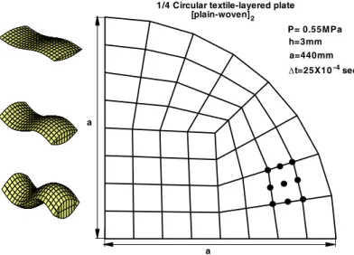
3.2 Dynamic Behavior of Textile Shells To evaluate the dynamic behavior of textile composite shell structures, this study considers a clamped circular textile-layered plate subjected to a suddenly applied uniformly distributed load shown in Fig.5. Material property of Hercules of AS4 Graphite & 3501-6 Epoxy suggested in Ref. [3] is used. The plate shown in Figure 25 consisting of 41 elements is subjected to a distributed step pressure of P =0.55MPa using the time stepΔt=25E-4 sec and boundary conditions of clamped edges are used. The radius and thickness are
=
a 440mm and h=3mm are considered. Layers of plate consist of two plain–woven textile layers modeled by Sine Function Model I (SFM I)13 and yarn sizes of 2K, 10K and 18K are used here. Here, K means 1000 fiber bundles within a yarn. Figure 6 shows that the large yarn size has larger deflections to the uniform loading.
In Fig.7 a textile-layered spherical cap subjected to a suddenly applied uniformly is described. Material property of E-glass/Vinylester suggested in Ref. [4] is used. The 41 degenerated shell elements, the uniform pressure P=6psi, the time stepΔt=1E-5sec, the radius
=
R 13in, the thickness t=0.03in and the central angle of α=23oare considered respectively. The shell stacking sequence is [plain-woven]3 modeled by Sine Function Model I and the yarn geometry is given in Ref. [4].
Figures 7 show that the crack densities and gap lengths affect the central deflections. From Fig. 7, large values of crack density show large changes in deflections with increases in gap lengths.
From Figs. 6 and 7, the dynamic behavior of textile composite shells is considerably related to geometrical shapes of strands. In the first case of Fig. 6, the three yarn cases (2K, 10K and 18K) made a little different time history of central deflections. However, the trend curves of Fig. 7 are showing the same tendency of central deflections with different magnitudes during the infinitesimal time steps. In the second case of a spherical textile layered cap shown in Fig. 7, this study investigates the dynamic behavior of textile layered caps consisting of various gap lengthened yarns under a uniform pressure. And also different crack densities and a constant fiber volume fraction are considered to check
the dynamic behavior of spherical textile layered cap under the uniform pressure. As shown in the first case of a clamped circle textile layered plate, the central deflection time history of spherical textile layered cap show the considerably geometrical dependency of strand shapes. The geometrical yarn dependency of textile layered shells and plates are basically induced from yarns’ material properties connected with yarn formations. For example, a large sized yarn makes more curved arc-lengths along the center line of yarns, while a small sized yarn shapes a little curved center line along the fiber bundle axis. When more curved arc-lengths for the large sized yarns make large crimp angles with respect to different bent regions of strands, the transverse direction components of yarn stiffness are more various values compared to those of the small sized yarns. More detailed phenomena for yarn crimp angles are presented in Refs. [5-6].
4. Summary
This study shows the dynamic behavior of general shell structures and textile layered composite structures on the transient loading. From the current numerical analyses, we can see that the presented hierarchical modeling for textile layered shells is very effective to depict the dynamic behavior. Although the geometrical model of textile layered shells is a difficult model unlike general shell structures, this work shows that the present modeling of three-level hierarchical analysis effectively analyzed the textile layered structures’ dynamic response by employing the introduction of micro-mechanical equations on the composites, the concept of layer-wise analysis and the structural level approaches. With the numerical results, the textile composite structures are considerably dependent on the geometrical shapes of yarns in the unit cells. For example, the different strand of fills and warps induce variant stiffness of yarns during the micro-mechanical analysis. Furthermore the different stiffness induces various equivalent moduli of textile composite layers in the layer-wise analysis, and the dynamic response of textile layered shells is finally made.
From this work, some interested dynamic behavior of textile composites are briefly suggested, and other geometrical effects of yarns on the transient response of textile composites are presented. First of all, when the textile layered structures are analyzed, more exact modeling for geometrical yarn shapes and composites in the fill and the warp is needed. To obtain better solutions, there will be needed the exact geometrical variables of yarns and the appropriate continuum equations of fiber and matrix in the strands. In addition a better transient algorithm can make good solutions on the dynamic response of textile layered structures. For future challengeable researches, there are several different typed textile composite structures, i.e. 2-D braids and 3- D orthogonal weaves. From this point, the current research is studying a various types of 2-D plain weaves and applying to the three-level hierarchical analysis.
Acknowledgements
The authors acknowledged a number of discussions with the late lamented Prof. L. Librescu, Virginia Tech, on the composite shell structures and also appreciated helpful suggestions from Prof. M. Hyer, Virginia Tech, and Dr. A. E. Bogdanovich, 3-TEX Company, about the textile composite structures.
Reference
(1) Bogdanovich, A.E., “Multi-scale Predictive Analysis of 3-D Woven Composites,” Proceedings of the 35th International SAMPE Technical Conference, Vol. 35, Dayton, OH, September 28-October 2, 2003.
(2) Tan, P., Tong, L. and Steven, G..P., “Modeling Approaches for 3-D Orthogonal Woven Composites,”
Journal of Reinforced Plastic and Composites, 1998, Vol.17, No. 6, pp. 545-577.
(3) Naik, R.A., “Analysis of Woven and Braided Fabric Reinforced Composites,” NASA Contract Report CR- 194930, 1994.
(4) Scida, D., Aboura, Z., Benzeggagh, M.L. and Bocherens, E., “A Micro-mechanics Model for 3D Elasticity and Failure of Woven-Fiber Composite Materials,” Composites Science and Technology, Vol.
59, No.4, 1999, pp. 505-517.
(5) Hur, H.-K, Johnson, E. R. and Kapania, R.K., “A Simple Homogenization of Degraded Micro-Cracked Plain Woven and Braided Textile Composites,” The 47th AIAA/ASME/ASCE/AHS/ASC Structural Dynamics and Materials Conference, May 1-May 4, 2006, Rhode Island, Newport, AIAA-2006-1692.
(6) Hur, H.-K, Johnson, E. R. and Kapania, R.K.,
“Degraded Strength Prediction of Micro-Cracked Plain Woven Textile Composites,” The 47th AIAA/ASME/ASCE/AHS/ASC Structural Dynamics and Materials Conference, May 1-May 4, 2006, Rhode Island, Newport, AIAA-2006-2173.
(7) Hur, H.-K. and Kapania, R.K., “Impact of Plain Woven Textile-Ceramic Plates Using Macro/Meso Modeling,” The 48th AIAA/ASME/ASCE/AHS/ASC Structural Dynamics and Materials Conference, April 23-April 26, 2007, Honolulu, Hawaii, AIAA-2007- 1996.
(8) Hur, H.-K. and Kapania, R.K., “The Mechanical Characteristics of 2-D Braided Textile Composite Using Geometrical Representation,” The 48th AIAA/ASME/ASCE/AHS/ASC Structural Dynamics and Materials Conference, April 23-April 26, 2007, Honolulu, Hawaii, AIAA-2007-2402.
(9) Hinton, E., Owen, D.R.J. and Shantaram, D.,
“Dynamic Transient Linera and Nonlinear behavior of Thick and Thin Plates, “The Mathematics of Finite Element and Applications II (MAFELAP 1975), Academic Press, New York and London, 1976, pp.
423-438.
(10) Reismann. H. and Lee, Y.C., “Forced motion of Rectangular Plates,” Proceedings of the 4’th Biennial
South-Eastern Conference, Tulane University, New Orleans, Pergamon Press, New York, 1968.
(11) Reismann. H. and Tendorf, Z.A., “Dynamics of Initially Stressed Plates,” Journal of Applied Mechanics, Vol. 43, June, 1976, pp. 304-308.
(12) Hinton, E., “The Dynamic Transient Analysis of Axisymmetric Circular Plates by the Finite Element Method,” Journal of Sound and Vibration, Vol. 46, No.4, 1976, pp. 465-472.
(13) Hur, H.-K. and Kapania, R.K., “Analytical Modeling Problems of 2-D Plain Woven Textile Composites Using Geometrical Representations,” The 18th Engineering Mechanics Division Conference of the American Society for Civil Engineers, June3-June 6, 2007, Virginia Tech, Blacksburg, Virginia.
Fig. 1 2-D plain weaves and 3-D orthogonal weaves.
Fig. 2 Unit cell shape of 3-D weaves with small cracks.
Fig. 3 Plate geometry, loading and bending moment history for an initially stressed plate11.
2-D plain weave textile
3-D orthogonal woven textile
Warp yarn
Fill yarn Z-yarn
Resin
X Y Z
β 2a
2a
v = u x
u = 0 .4 in
U .D .L ., q
a = 1 . 4 1 4 2 in
F Fx
b = 1 .0 in
0.0 2.5 5.0 7.5 10.0 12.5 15.0 17.5
0 5 10 15 20 25 30 35 40
Central bending moment
12Mx/(qh2 )
Static solution
Static solution Static solution
T/a(ρ/E)0.5 σx = 0.
σx = 1.0 (σ
x)cr/E σx = -0.5 (σ
x)cr/E
0.0000 0.0005 0.0010 0.0015 0.0020 -2.0
-1.6 -1.2 -0.8 -0.4 0.0 0.4
B C
B C
B A
Central deflection time history for a textile-layered plate
Central deflection (mm)
Time (sec) 2K 10K 18K
Fig. 4 Circular plate and bending moment history12.
Fig. 5 Three yarn sizes and symmetric quadrant of clamped circular textile-layered plate.
Fig. 6 Central deflection time history.
Fig. 7 Spherical textile layered cap with uniform pressure and central deflection time histories with various crack densities and gap-lengths.
=10 lb-sec /in
a a
q=0.1lb/in E=100 lb/in h=20 in
=0.3 2 4
ρ Δ
2
t=0.6sec 2
a=100 in υ
0 100 200 300 400
-50 0 50 100 150 200 250
Central bending moment (lb in/in)
Time (sec)
Bending moment
a a
1/4 Circular textile-layered plate [plain-woven]2
Δt=25X10 sec a=440mm h=3mm P= 0.55MPa
-4
0.000 0.001 0.002 0.003 0.004 0.005
-0.12 -0.10 -0.08 -0.06 -0.04 -0.02 0.00 0.02 0.04 0.06 0.08 0.10
Crack density β = 0.8, Fiber volum fraction Vf = 0.8
Time (sec) g = 0. in
g = 0.004 in g = 0.008 in
Deflection, w0 (inch)