• 검색 결과가 없습니다.

Design Verification of APR1400 Reactor Vessel Through Re-engineering Approach

N/A
N/A
Protected

Academic year: 2021

Share "Design Verification of APR1400 Reactor Vessel Through Re-engineering Approach"

Copied!
9
0
0

로드 중.... (전체 텍스트 보기)

전체 글

(1)

www.kosse.or.kr

Design Verification of APR1400 Reactor Vessel Through Re-engineering Approach

Mutegi Peter Mutembei, Ihn Namgung

*

KINGS (KEPCO INTERNAL NUCLEAR GRADUATE SCHOOL

Abstract : This paper describes verification of APR1400 reactor vessel by applying the system engineering approach, in which the design re-engineering method is used to check the design parameters of APR1400 RV (reactor vessel). The RV is classified as safety class 1 and therefore must adhere strictly to the rules of ASME BPVC section III, subsection NB and seismic category I. This study explores designing the RV by following the ASME guidelines and making a comparative study with the current design. To meet this objective we apply system engineering methodologies to structure the process and allow for verification and validation of the major RV design parameters such as thickness of RV. The structural thicknesses of various part of RV are determined as well as reinforcements on the RV major nozzles. A 3D virtual reality model was created based on the design parameters using CATIA V5 and animation using Dassault Composer V2016. A comparison of re-engineered ARP1400 RV and standard APR1400 RV was done to show which design parameters were taken more conservative approach.

Key Words : Re-engineering, APR1400, Reactor Vessel, Nuclear Component

Received: November, 2016 / Revised: June 21, 2017 / Accepted: June 26, 2017

* Corresponding Author : Ihn Namgung, [email protected]

This is an Open-Access article distributed under the terms of the Creative Commons Attribution Non-Commercial

License(http://creativecommons.org/licenses/by-nc/3.0) which permits unrestricted non-commercial use, distribution,

and reproduction in any medium, provided the original work is properly cited.

(2)

[Figure 1] Reactor vessel assembly manufacturing process

1. Introduction

The RV is classified as safety class 1 and therefore must adhere strictly to the rules of ASME BPVC section III, subsection NB. Figure 1 shows the RV and its subparts. The RV forms the primary pressure boundary of Nuclear Steam Supply System, supports reactor internals and core and provides coolant flow path. There are 4 inlet nozzles and 2 outlet nozzles for coolant flow, and 4 direct injection nozzles and 61 ICI nozzles (bottom mount nozzles). The RV is supported vertically by 4 columns attached to cold-leg and horizontally by 4 shear lugs at the bottom of outside bottom head. The 4 shear lugs and base plate of support columns allows expansion of RV due to temperature rise while restraining horizontal movement during seismic events.

Figure 1 shows manufacturing process of reactor vessel. All of the sub-parts of the reactor vessel are made of forgings from ring for shell part and plate for head part. These forged parts are then cladded and welded together to form reactor vessel. The core region is made out of one shell section to prevent adverse effect on the reactor vessel

from welding process. Note also current RV manufacturing has been improved so that all weldings in RV are in circumferential weld and there are no longitudinal welds. The change of fabrication practice is to reduce the chances of stress corrosion cracking in the longitudinal weld.

The basic shape of RV is cylinder and sphere and openings for nozzle. Stresses in cylinder and sphere could be predicted accurately, but stresses rear by openning is not. The numerous nozzles/ openings that provide interface points to other systems and components form geometric discontinuities that create stress concentration. Henc there's a need to ascertain that proper structural compensation is made to ensure safety. The ASME BPVC section III, subsection NB provides guidelines for the design of vessel thickness and nozzles. The re-engineered design carried out in this study followed the ASME procedure. These ASME procedure is minimum guidelines to ensure safety of RV.

2. System Engineering Process

The system engineering approach takes on the design process of the system as a whole rather than focusing on individual components.

2.1 System Engineering Methodology

At the highest level, the systems engineering

methodology focuses on several major steps

including: problem statement, identification of

objectives and requirements documentation,

concept generation, analysis of alternatives

and trade studies, selection of primary concept,

system creation, including decomposition, design,

(3)

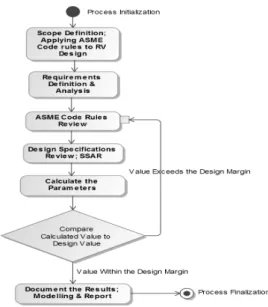
[Figure 2] Process Activity Relationships

[Figure 3] Flow chart of the project process

[Figure 4] Project process V-model

development, integration, verification and validation, and system operation and life cycle disposal.

The system is then physically reconstructed from its individual components into subsystems and eventually integrated into a complete system.

These steps are typically combined together in a manner that decomposes the problem into subsystem and eventually component-level

“pieces” that can be handled by individual engineers. Plans are created by the System Engineer to ensure that the subsystems and overall system perform as designed (verification) and ultimately meet the desired intent of the customer (validation) by performing the desired function.

Implementing the system engineering approach assesses the problem in a more efficient manner and makes the application of the desired codes for the RV design easy. When analyzing the RV structural design, and combining the desired codes, the output will be a design that satisfies the ASME code rules. This procedure is shown in Figure 2.

Figure 3 shows a flow chart representing the decision making process for the project.

The re-engineering process is represented in the V-model shown in Figure 4 below. It is a systematic approach to understand and project requirements of the client and maps these

requirements to process definitions. The V-model also performs reviews on multiple levels tracing all requirements through the entire project life cycle so as to ensure clear and unambiguous requirements.

2.2 Systems Engineering Requirements of ASME Design by Formula

In this study, ASME Section III Subsection

NB code requirements are considered as minimum

requirements. Any additional requirements by owner

or regulatory body will be additional requirements

which will increase conservatism in the design

of RV.

(4)

ASME code requirement are mostly concerned about high pressure of primary system, and it contains two different procedures. One is for the design by stress analysis and the other is the design by formula. Since the procedure for the design by formula need to includes uncer- tainties, it is more conservative than the design by analysis. While design by analysis is more accurate and allows less conservative design, it requires detailed stress analysis and complete and lengthy documentation of the analysis result.

In this study, design by formula is taken as re-engineering design of RV. In essesce the cylindrical shell thickness of RV and bottom head thickness to determin.

- Cylindrical Shells (NB-3324.1)

- Spherical Shells (NB-3324.2)

where

P = Design Pressure

R = inside radius of shell or head R o = outside radius of shell or head

S m = design stress intensity values (Sec. II, Part D, Subpart 1, Tables 2A and 2B) t = thickness of shell or head

Other requirements are related to nozzle openings. Since opening in vessel weaken the strength, it has to be reinforced. The Opening Reinforcement is defined in NB-3332. This reinforcement are also limited to the vicinity of openings in order to effectively reinforce the openings. The limit of reinforcement is defined in NB-3334. The strength of reinforcing

matrerial is defined in NB-3336, and requirements on multiple opennings are defined in NB-3335.

Also special vessel requirements are define in NB-33360.

In the design of vessel, these requirements shall be meet as minimum. Any specific owner requirement and regulatory requirements are additional requirements.

3. Sizing Calculation Methodology

3.1 Core and Reactor Internals Design Data Since the design re-engineering is based on APR1400 reactor design, the core design of APR1400 is used to determine the inner diameter of reactor vessel. Figure 5 shows the APR1400 core arrangement.

[Figure 5] Core Arrangement of APR1400

With reference to APR 1400 SSAR, we get the parameters of Core Support Barrel and Core Shroud as shown in Table 1 below.

The arrangement of ractor core is shown in

Figure 6 with design parameters given in

Table 1 is used.

(5)

<Table 1> Core Support Barrel and Core Shroud parameters

Components Parameter

Core Shroud OD: 3987.8 mm (157 in) CSB ID: 3987.8 mm (157 in) Reactor Vessel ID: 4629.15 mm (182.25 in)

Ø3987.8mm ID Ø4629.15mm

Core Shroud

Core Support Reactor Vessel

Ø3987.8mm OD

[Figure 6] Reactor Core Cross Section

[Figure 7] ASME RV Material Specifications

3.2 Reactor Vessel Sizing

3.2.1 Operating Parameters and Materials APR1400 intrinsic material properties and operating conditions are tabulated in Table 2 and 3, and Figure 7.

<Table 2> APR 1400 RCS Design parameters

Parameter Value

Design thermal power, MWt 4000

Design pressure, kg/cm2A(psia) 175.8 (2500) or 17.237 MPa Design temperature, oC(oF) 343.3 (650)

<Table 3> Reactor Vessel Materials

Reactor Vessel Material Specification

• Forging part SA – 508, Grade 3 Class 1

• Plate part SA-533 Type B Class 1

3.2.2 Sizing Calculations

The procedural application of appropriate ASME code for determining the major design

parameters of the reactor vessel is as follows,

a. Reactor Vessel thickness of active core region:

Thickness of Reactor Vessel; ASME Code NB- 3324.1 Cylindrical Shells

     



Where:

P = 17.237 MPa: pressure inside of RV S m : Design stress intensity values (Section II, Part D, Subpart 1, Tables 2A and 2B), Sm= 26.7 ksi or 184 MPa

R: Inner radius of RV, dRV = 4629.15

   

  

    ×   ×

 ×

 

b. Reactor Vessel lower head thickness:

The reactor vessel lower head thickness is determined by using ASME Code NB-3324.2 for spherical shells; NB-3324.2 Spherical Shells

      

    ×   

 × 

 

c. RV lower head radius:

To ensure continuity of reactor vessel design,

we choose radius of RV lower head part equal

(6)

<Table 4> Diameter of Hot-leg and Cold-leg

Components Parameter

Hot-leg inner dia., mm (in) 1066.8 (42) Cold-leg inner dia., mm (in) 762 (30)

with the inner radius of RV, 2314.575 mm

d. Hot-leg and Cold-leg Sizing

i. Hot-leg and Cold-leg Thickness

According to ASME NB-3324.1 for Cylindrical Shells

     



Where:

- P: Design Pressure = 17.237 MPa - R = 1066.8: Inside radius of shell

- S m : design stress intensity values (Section II, Part D, Subpart 1, Tables 2A and 2B) - t: Thickness of shell

SA-508 Design Stress Intensity Value: Sm

= 184 MPa

      

      × 

 × 

  

      

      × 

 × 

 

ii. Hot-leg Reinforcement

According to NB3332.2 Required Area of Reinforcement:

The total cross-sectional area of reinforcement A, requires in any given plane for a vessel under internal pressure, shall not be less than

   ×  ×      Where:

d = finished diameter of a circular opening or finished dimension (chord length) of an opening on the plane being considered for elliptical and around openings in corroded condition. (in this

case d = 1066.8 mm)

F = a correction factor which compensates for the variation in pressure stresses on dif- ferent planes with respect to the axis of a vessel. In this case, we choose F= 0.5

tr =230 mm, the thickness which meets the requirements of NB-3221.1 in the absence of the opening.

Substituting these values to the equation returns the required area as,

A = 1,066.8 x 230 x 0.5 = 122,682 mm 2 According to NB-3334.1 Limit of Reinforcement along the Vessel Wall:

(a) One hundred percent of the required reinforcement shall be within a distance on each side of the axis of the opening equal to the greater of the following:

(1) The diameter of the ?nished opening in the corroded condition;

L limit - > D Hot-leg = 1066.8 mm

(2) The radius of the ?nished opening in the corroded condition plus the sum of the thicknesses of the vessel wall and the nozzle wall.

L limit > r Hot-leg + t v + t Hot-leg = 533.4 + 230 + 112.5= 875.9 mm

Comparing the 2 cases, one hundred percent of the required reinforcement shall be within a distance on each side of the axis of the opening:

L limit-1 = 1,066.8 mm

Required Area of Reinforcement not less than a half of the required material shall be on each side of the center line. It's mean: A v >

0.5A= 0.5 x 122682 = 61341 mm 2 , so the thickness of material add along the vesssel wall is:

  ∙      ⇒    



  

(7)

(b) Two-thirds of the required reinforcement shall be within a distance on each side of the axis of the opening equal to the greater of the following:

(1)      , where R is the mean radius of shell or head, t is the nominal vessel wall thickness, and r is the radius of the finished opening in the corroded condition;

     

lim             × 

 

(2) The radius of the finished opening in the corroded condition plus two-thirds the sum of the thicknesses of the vessel wall and the nozzle wall.

        

     

      

     

Combine 2 cases, Two-thirds of the required reinforcement shall be within a distance on each side of the axis of the opening

L limit-2 = 907.16 mm

So the thickness of two third of the required reinforcement is:

 

     ∙     ⇒      × 

 × 

  

Hence,       

According to NB-3334.2 Limit of Reinforcement;

Normal to the Vessel Wall



  

 

where,

r i : inside radius of nozzle

r m : mean radius = r i +0.5t n = 533.4+0.5t n

r 2 : transition radius, between nozzle and wall (choose 50 mm)

t n : nominal nozzle thickness, as indicated t n = t 0 +t reinforcement . Where t 0 = 104.8 mm By iteration methodology we apply values of

treinforcement from 0, 10, 20.... to find L limit-2

We get the value of thickness of reinforcement:

t reinforcement = 150 mm and the long of reinforcement is: L Limit-2 = 233.8 mm

At that point, the thickness of Hot-leg after reinforcement is: t n = 262.5 mm

iii. Cold-leg reinforcement

The radius and thickness of cold-leg had been calculated previously.

t cold-leg =74.89 mm R Cold-leg =381 mm According to NB3332.2 Required Area of Reinforcement:

The total cross-sectional area of reinforcement A, requires in any given plane for a vessel under internal pressure, shall not be less than

  ×

×   

 

  × × ×  

- According to NB-3334.1 Limit of Re- inforcement along the Vessel Wall:

(a) One hundred percent of the required reinforcement shall be within a distance on each side of the axis of the opening equal to the greater of the following:

(1) The diameter of the finished opening in the corroded condition;

L limit > D Cold-leg = 762 mm

(2) The radius of the finished opening in the corroded condition plus the sum of the thicknesses of the vessel wall and the nozzle wall.

L limit > r Hot-leg + t v + t Hot-leg = 381 + 230 + 80 = 691 mm

Comparing the 2 cases, One hundred percent of the required reinforcement shall be within a distance on each side of the axis of the opening:

L limit-1 = 762 mm

Required Area of Reinforcement not less

than a half of the required material shall be on

(8)

each side of the center line. It's mean:

    ×     , so the thickness of material add along the vesssel wall is:

   ∙     ⇒     



  

(b) Two-thirds of the required reinforcement shall be within a distance on each side of the axis of the opening equal to the greater of:

      , where R is the mean radius of shell or head, t is the nominal vessel wall thickness, and r is the radius of the finished opening in the corroded condition;

     



 

 

  

      ×  

Two-thirds of the required reinforcement shall be within a distance on each side of the axis of the opening

L limit-2 = 754 mm

So the thickness of two third of the required reinforcement is:

 

     ∙     ⇒      × 

 × 

  

t V2 < t V1 ; So the thickness of material added along to the vessel will be 57.6 mm

• Limit of Reinforcement of Cold-leg Normal to the Vessel Wall

 ≥       Where:

r i : inner radius

r m : mean radius = r i + 0.5t n = 381+0.5 x t n

r 2 : transition radius, between nozzle and wall (choose 50mm)

t n : nominal nozzle thickness, as indicated = t cold-leg + t reinforcement

We can find the value of t reinforcement by

iteration. The iteration was done for initial value of t reinforcement from 0, 10, 20 and found the final value of L limit-2 .

We get the value of thickness of reinforcement : t reinforcement = 120 mm and the length of reinforcement is: L Limit-2 = 209 mm

Considering the limit of reinforcement and thickness for various cases, the resulting thickness of Hot-leg after reinforcement is: t n = 210 mm.

4. Sizing result and 3D Design of RV

In the previous chapter, important design parameters were shown how to drive them.

Table 5 below summarize the results.

Figure 7 and 8 show the 3D design result that was carried out using CATIA V5.

No. Parameter Re-eng.

(mm)

Standard (mm) 1 RV active core region thickness 227 230

2 RV nozzle region thickness (not

including the reinforced section) 227 285 3 RV bottom head thickness 114 165 4 RV bottom head inner radius 2315 2330

5 RV Inner radius 2315 2330

<Table 5> Re-engineered design parameters and APR1400 RV design parameters

No. Parameter Re-eng.

(mm) Standard (mm)

6 Hot leg thickness 105 112.5

7 Cold-leg thickness 75 80

8 Hot-leg reinforcement thickness

along the vessel wall 58 55

9 Hot-leg reinforcement length

along the vessel wall 1067 ext.

nozzle region 10 Hot-leg reinforcement thickness normal to the vessel wall 150 195

11 Hot-leg reinforcement length

normal to the vessel wall 236 355 12 Cold-leg reinforcement

thickness along the vessel wall 58 55 13 Cold-leg reinforcement length

along the vessel wall 762 ext.

nozzle region 14 Cold-leg reinforcement thickness

normal to the vessel wall 150 235 15 Cold-leg reinforcement length

normal to the vessel wall 194 450

(9)

[Figure 7] ASME Code specification RV geometrical model

[Figure 8] Current design specification RV geometrical model

5. Conclusion

In this study only the major mechanical design parameters of the RV was explored whereas thermal-hydraulic functionality considerations

were referred directly to the SSAR. The calculated design parameters, namely the thickness of reactor vessel parts, were lower compared to those of the standard APR1400 design. It showed that the APR1400 standard design parameters of RV exceed the ASME margins;

this indicates a conservative structural design approach in the APR1400 reactor vessel. Thus ensuring structural integrity for the component.

Acknowledgements

This work was supported by the 2016 Research fund of the KEPCO International Nuclear Graduate School (KINGS), Republic of Korea. The authors would like to express appreciation toward KINGS.

References

1. Kossiakoff, A. and W.N. Sweet, Systems Engineering: Principles and Practice, Wiley- Interscience, Hoboken, NJ, pp. 69-109, 2011.

2. INCOSE, “Systems Engineering Handbook”, version 3.2.2., INCOSE TP-2003-002-03.2.2., pp. 61-218, October 2011.

3. ASME, 2010. “Section III, Division 1 - NB. Article NB-3000 Design”

4. Ihn Namgung, Conceptual Design of PWR600 Reactor Pressure Vessel Mechanical Design, KINGS textbook, 2015

5. Korea Electric Power Corporation and

Korea Hydro & Nuclear Power Co., Ltd.,

2001, “APR1400 SSAR (Standard Safety

Analysis Report)”, Republic of Korea,

Chapter 4 Reactor.

수치

Figure  1  shows  manufacturing  process  of  reactor  vessel.  All  of  the  sub-parts  of  the  reactor  vessel  are  made  of  forgings  from  ring  for  shell  part  and  plate  for  head  part
Figure  3  shows  a  flow  chart  representing  the  decision  making  process  for  the  project
Figure  7  and  8  show  the  3D  design  result  that  was  carried  out  using  CATIA  V5.

참조

관련 문서

Current APR1400 CPCS requirement and DNBR algorithm are analyzed in the reverse engineering process and FPGA based DNBR algorithm design and development are done

In this paper, an event/accident simulation model for ³Human´KDVEHHQGHYHORSHG, which is one of level 1 performance shaping factor for the reactor pressure vessel

This study describes a case study of convergence of curriculum and engineering and design, focusing on the 2019 comprehensive engineering design subject of the researcher..

This paper suggests a system framework and its essential components for the verification of a pressure vessel design using the industrial standards of Korea.. The authors

In this paper, a new approach of engineering education based on academia-industrial cooperation and design-centered teaching technique for the students who need

Park, S Kwon Korea Electrotechnology Research Institute Abstract - This paper deals with the design of control cabinet.. based on safety PLC for reactor

Abstract In this paper, we introduce a model of the teaching and learning method for multidisciplinary convergence capstone design at Kongju National

Abstract : This paper describes a design and a verification of linear state observers for a motorized seat belt system to estimate state information such as angular velocity