• 검색 결과가 없습니다.

A Study on the Robot Structure of Hand for the Rehabilitation Training of Stroke Patients

N/A
N/A
Protected

Academic year: 2021

Share "A Study on the Robot Structure of Hand for the Rehabilitation Training of Stroke Patients"

Copied!
9
0
0

로드 중.... (전체 텍스트 보기)

전체 글

(1)

학 술 논 문

http://dx.doi.org/10.9718/JBER.2019.40.3.116

116

A Study on the Robot Structure of Hand for the Rehabilitation Training of Stroke Patients

Jong-Bok Kim 1,3 , Jong-Chul Kim 2,3 and Dae-Joon Hwang 1

1

Graduate School of Department of Electrical and Computer Engineering of Sungkyunkwan University

2

Department of Mechanical Design and Product Engineering of Konkuk University

3

Research and Development Center of Yoi System (Ltd.)

(Manuscript received 10 April 2019 ; revised 21 June 2019 ; accepted 21 June 2019)

Abstract: The rehabilitation training robots for treating the upper limbs of stroke patients were mainly focused on the upper proximal treatment of it, but recently studies of the distal parts of the upper limbs for rehabilitation of the hand is making some progress even though it is still a small number so far. In this paper, we present the hand robot for the rehabilitation training of stroke patients that is the fingertip contact-typed mechanism, and it has also equipped with the wrist rehabilitation unit to be worked like human hand that enables any movements through mutual coop- eration by fingers while picking up or grasping objects. The robot that is presented for this purpose supports the movement of fingers with 5-DoF and the wrist with 3-DoF that moves independently, and operates with a structure that allows the joints of the wrist and fingers to be collaborated organically together to each other. Also, hereby the simulation and evaluation test on its robot mechanism are performed to ensure that fingers with 5-DoF and the wrist with 3-DoF of the serial kinematical mechanism are designed to comply with or exceed ROM for ADL.

Key words: Stroke rehabilitation, Rehabilitation robot, Modified scott-russell mechanism, Degrees of freedom, Serial kinematic mechanism with 3-DoF

I. Introduction

Stroke is a disorder of the cerebral blood system that involves paralysis of the whole body, one side of the body, or some of the body, causing the complete immobilization or the partial motion. This causes all muscles, such as skeletal muscles and knuckle mus- cles, to stiffen up, which each muscle of them may be relaxed through proper exercise. For these stroke patients, continuous and repetitive rehabilitation training can be performed to recover or improve damaged functions, and it may be more effective to use the robot as an aid to cause repetitive motion [1,2]. The robot with the fin- gertip contact-typed method proposed in this paper is

also one of the hand rehabilitation robots, which is still a small number so far but is making some prog- ress [1].

Hand rehabilitation robots can be divided into finger joint contact-typed robot and fingertip contact-typed robot depending on the shape they implement respec- tively. The study in this paper performs a hand reha- bilitation robot that can perform natural daily actions for rehabilitation training of stroke patients with smaller and simpler structure compared to others, and adds the function of wrist rehabilitation into it for collab- oration with each other. The proposed robot enables to carry out the hand and wrist rehabilitation performing movements in which wrist and hand can collaborate organically together. The robot that is presented for this purpose also supports the movement of finger with 5- DoF (Degrees of Freedom) and the wrist with 3-DoF (Degrees of Freedom) that move independently, and operates with a structure that allows the joints of the wrist and fingers to be linked together to each other [2-4].

Corresponding Author : Dae-Joon, Hwang

Department of Electrical and Computer Engineering of Sungkyunkwan University

Tel.: +82-31-290-7109 E-mail: [email protected]

This research was conducted with the support of project of

Small and Medium Business Administration: "The development

of hand and wrist for active rehabilitation training device

based on VR".

(2)

117 In this paper, the mechanism structure of fingers

with 5-DoF based the modified scott-russell linkage struc- ture is implemented and simulated by SolidWorks to validate. Hereby these fingertip movements by the link- age traveling along with the straight-line motion of the actuator are similarly moving such as a trajectory of the human finger’s movement. And this is also ver- ified whether the wrist 3-DoF mechanism meets or exceeds ROM (Range of Motion) for ADL (Activity for Daily Living) required in rehabilitation training for stroke patients [5,6].

II. Design of Rehabilitation Robot

1. Hand’s mechanism structure with 5-DoF

In order to design the rehabilitation robot for hand and wrist in a fingertip contact-typed so that it can move naturally, it is necessary to derive the motion of movements and their trajectory traveled by biomechanical structure in hand and wrist that consist of a lot of complex joints and muscles organically working with collaboration [1,7]. For deriving it, hand’s anthropo- metric data such as those shown in Fig. 1, which pres- ents the hand length, length of each fingers, angle of finger flexion and joints, angle of thumb radial adduc- tion including index finger, and etc. by A.R Tilley et al. [8], has been generated into kinematic mechanical factors that are useful for its robot design. And, based

on this, the work of modeling the human hand accord- ing to the kinematic mechanism is carried out.

Hereby the calculated factors by modeling the human hand is analyzed by forward kinematics derived the cartesian coordinate (x-y position) from the angular coordinate of the joint, or inverse kinematics derived the angular coordinate of the joint unit from the car- tesian coordinate (x-y position), which applies to the design of the kinematic structure for robot in order to travel in similar trajectory such as human fingers.

And with the range of motion presented by D.A. Neu- mann’s study on the range of motion of finger knuckles [9] and by S.L. Delp et al.’s study on the range of motion of the wrist joint[10], we will reflect them on the design of rehabilitation robot with the target performance and evaluate whether robot is satisfied. Hereby respectively, Table 1 shows the range of motion with respect to the knuckles of fingers with the metacarpophalangeal (MCP), proximal interphalangeal (PIP) and distal interphalan- geal (DIP), and also Table 2 shows the range of motion with respect to the wrist joint.

(1) Design of single finger

In this paper, we adopts the modified scott-russell linkage mechanism by enhancing scott-russell link- age mechanism which is a structure that can basically output a straight-line motion of input by redirecting it to 90 degrees, and presents the design of finger robot based on it [7].

Fig. 1. Structure of human hand.

Table 2. ROM on Wrist Joint

Wrist Movement Normal Range of Motion (deg.)

Flexion 65-80

Extension 55-70

Radial Deviation 15

Ulnar Deviation 30

Pronation 75

Supination 85

Table 1. Finger ROM on MCP, PIP, DIP

Finger Movement Normal Range of Motion(deg.)

MCP 0-90

PIP 0-100

DIP 0-70

(3)

118

The modified scott-rusell linkage mechanism pre- sented in this paper holds an angle of 15 degrees by adding the structure of point-A kind of things as shown in Fig. 2, and places each linkages into 120 mm for AC, 70 mm for OC, 82 mm for CD, 110 mm for BD and 137.2 mm for BC as shown in Table 3. Hereby while point-A with 126.7 degrees of Point-C moves to the horizontal direction (X-axis) by straight-line motion, point-B which is an end-effector, moves in a nonlinear trajectory with similar movements such as a motion trajectory at human fingertip.

In Fig. 2, while point-A that is actuator is straight- ened 59.5 mm from A0 to A10 along a direction of the driveshaft, point-B that is an end-effector travel in conjunction with a linkage on the X-Y plane to move 95.34 mm from B0 to B10 as shown in Table 5. As a result, Bxy X-Y coordinate of point-B which is an end- effector, become a nonlinear trajectory as shown in Fig. 3. And the setting of the length of fingers can be

fitted by adjusting the traveling distance of point-A because the length of fingers may be different per per- son.

Fig. 4 shows a finger robot of the single-finger mecha- nism designed based on the movement trajectory of the fingertip, which consists of two links ( OC, AB) and one drive unit that equips with motor, ball-screw, and linear guide.

(2) Design of hand mechanism with five-fingers The finger rehabilitation unit combines five single- finger robots to form a hand, and hand robot with five fingers is attached to the main fixed plate to form a five-finger structure. Hereby fingers in the right to left order become thumb, index, middle, ring, and lit- tle finger respectively. The hand robot unit is coupled to the wrist robot unit through a fixed hole located at the back of the fixture plate.

Fig. 2. The modified scott-russell linkage mechanism.

Table 3. Length of the modified scott-russell linkage

Linkage AC OC CD BD BC Slope angle (deg.)

Length (mm) 120 70 82 110 137.2 15

o

Fig. 3. Trajectory graph of Bxy-axis.

Fig. 4. Mechanism of single finger robot.

Fig. 5. Hand mechanism with five-fingers.

(4)

119 Fig. 5 shows an interval angles between the fingers

in the finger robot, and A.R Tilley et al. presents the angle of a maximum of 80° about thumb radial adduc- tion [8].

This hand robot has layouted the interval angle of 20° from little finger to index finger and the interval angle of 70° between index and thumb respectively.

Hereby those angles of fingers are also derived from the hand’s anthropometric data with performing a lot of experiments about whether robot motion are syn- chronized organically to the trajectory of the fingertips that is applied with a modified scott-russel linkage mechanism, driven individually by the attached drive unit.

And one left thumb also adds to the kinematic struc- ture of the proposed hand with five fingers to form a symmetrical structure, with the right hand and the left hand combined.

2. Design of wrist mechanism structure with 3-DoF The wrist robot unit consists of a three-motor drive unit, a reduction gear that decelerates the speed of the fast rotating drive, a fixed part of finger robot, and an instrumental structure unit with forearm guide and main body coupled with 3-Armbars. Fig. 6 shows the wrist robot unit.

Hereby to get it to form 3-DoF, the three motors are respectively positioned so that they each face the ori- gin of the center of the wrist rotation and coincides with the axial lines in x, y, and z three directions [3].

Motor-1 is driven to produce radial deviations of the wrist head toward the thumb and ulnar deviations of the wrist head toward the little finger respectively.

Motor-2 produces a movment that flexes or extends

the wrist, and motor-3 performs a motion that is respectively pronated or supinated in the wrist of forearm.

To do a rehabilitation training of hand, here is that should be carried out traveling human hand along the forearm guide and with the back of hand facing upward, placing the tip of five fingers on the robot’s finger, then fastening the wrist with a velcro.

III. Simulation on Fingers with 5-DoF

In this paper, the trajectory of point-B, which is the individual finger mechanism designed to behave sim- ilarly as if the motion trajectory of the fingertip as shown in Fig. 7, is analyzied by the forward kine- matics the values derived the cartesian coordinate of the x-y position on point-B working as an end-effector from the angular coordinate of point-B, and also per- forms to simulate by solidworks that enables the closed loop simulation.

Fig. 8 shows each correlation in which point-B is going to be moved while point-A of the drive unit trav- els along its driveshaft. In Fig. 8(a), A0 is an origin point, which is the default position before the drive unit is moved, and the status values associated with the point-A travel, Bx X-axis coordinate, By Y-axis coordinate, and point-B travel distance then become all zero. Fig. 8(b) shows that the coordinates of Bxy results in X-axis 30.25 mm and Y-axis 23.56 mm, while point-A travels 29.75 mm from A0 to A5 with 29.75 mm along its driveshaft, which point-B become to B5 with 38.34 mm in conjunction with it respectively.

In Fig. 8(c), this also shows that the coordinates of Bxy results in X-axis 70.14 mm and Y-axis 64.57 mm, while point-A travels from A5 to A10 with 59.50 mm along its driveshaft and point-B become to B10 with

Fig. 6. Mechanism structure of wrist with 3-DoF. Fig. 7. Mechanism structure of single finger.

(5)

120

93.34 mm.

Fig. 9 respectively shows, while the straight-line move- ment of point-A travels from A0 to A10 sequentially, on the trajectory of the Bxy moving in conjunction with its 11 points. In Table 4, it shows to be summarized the movement distances and Bxy X-Y coordinates at which point-B moves while point-A travels from A0 to A10 along the drive shaft. As a result, Bxy X-Y coordinate of point-B which is an end-effector, is orbiting in non- linear its movement trajectory as shown in Fig. 3.

IV. Prototype and Performance Assesment

1. Prototype of the proposed rehabilitation robot Fig. 10 shows that implements the robot based the fingertip contact-typed for a rehabilitation training of hand and wrist of stroke patients.

This robot consists of a wrist rehabilitation unit and a finger rehabilitation unit respectively, and the fin- ger rehabilitation unit located in the front is tightly attached to the arm plate located in the front of the wrist rehabilitation device.

The wrist rehabilitation unit consists of a three-motor drive unit, a reduction gear that decelerates the speed of the fast rotating drive, a fixed part of finger robot, Fig. 8. Bxy trajectory. (a) point-A0 (b) point-A5 (c) point-A10.

Fig. 9. Kinematic simulation of finger.

Table 4. Finger’s kinematic trajectory

Items A0 A1 A2 A3 A4 A5 A6 A7 A8 A9 A10

Movement Length of

Point-A (mm) 0 5.95 11.90 17.85 23.8 29.75 35.70 41.65 47.60 53.55 59.50

Bx (mm) 0 5.70 11.54 17.54 23.76 30.25 37.07 44.31 52.09 60.6 70.14

By (mm) 0 3.63 7.80 12.50 17.74 23.56 30.00 37.13 45.10 54.12 64.57

Movement Length of

Point-B (mm) 0 6.76 13.92 21.54 29.65 38.34 47.68 57.81 68.90 81.25 95.34

Fig. 10. Robot for rehabilitation training of hand and wrist.

(6)

121 and an instrumental structure unit with forearm guide

and base plate coupled with 3-Armbars. This, based 3- DoF, performs activities such as the wrist movement of flexion and extension including radial deviation, ulnar deviation, pronation, and supination.

The finger rehabilitation unit has five-fingers with individual one, based 1-DoF, attached to the main plate respectively. Whereby the finger robot performs cor- responding movements according to the force magni- tude measured by the force sensor attached to a tip of the finger, in which the robot's finger movements per- form natural movements similar to the trajectory of the human finger.

The operation of this robot for a rehabilitation train- ing of hand and wrist of stroke patients works by acti- vating the robot control in main control unit. To do it, in advance here is that should be carried out traveling human hand along the forearm guide and with the back of hand facing upward, placing the tip of five fingers on the robot’s finger sensor, then fastening the wrist with a velcro. The pictures in Fig. 10 show the proposed robot of prototype unit, the wrist fixed to the robot stand, and the fingers placed on the robot finger.

2. Structure comparison on rehabilitation robots In this chapter, we examine the advantages and dis- advantages through comparing the rehabilitation robot presented in this paper with the main characteristics and structures on hand robot of Amadeo

®

robot and the Wage’s robot. This cross-comparison is performed about numbers of DoF, the mechanism structure, num- bers of motor, finger attachment method, and hand fixture.

Fig. 11 shows wage’s hand robot [7], Amadeo

®

hand robot [11], and the proposed robot in this paper respec- tively.

Wage’s hand robot is one of the finger joint contact- typed robot as shown in Fig. 11(a) and equipes with 20 actuators for supporting 20-DoF [4]. This robot enables a natural hand movements, while increasing numbers of actuator and sensor that actuates hand movements, and complicating the structure of robot mechanism, resulting in larger size. It also causes the increase of robot weight as well as requiring a series of complicated processes to put on, so resulting in inconvenience in use.

Tyromotion Amadeo

®

robot is a fingertip contact- typed robot with five degrees of freedom, consisting of the movement mechanism with sliders, magnets, hand and arm support aids, and electronic lifting column height adjusting, which provide the movement of flex- ion and extension on four fingers and the thumb respec- tively.

Amadeo

®

robot has the structure with two sliders

dividing the thumb and the rest of the fingers as shown

in Fig. 11(c). To attach human finger to robot finger,

in advance it attaches the finger support with perma-

nent magnet to human finger, and then is connected

to the robot's fingertip via magnet couplings using

plasters. This robot is mainly offered the rehabilita-

tion training for flexion and extension exercise of patients

with motor disorders in the hands, and the various

types of finger support sizes are also provided for dif-

ferent hand size of human. And human arm is attached

Fig. 11. Rehabilitation robot. (a) wage’s robot (b) Amadeo

®

robot-hand fixation (c) Amadeo

®

robot-finger sliders for thumb

and other fingers (d)the proposed robot.

(7)

122

to the hand and arm support aids with the hook and loop fasteners as shown in Fig. 11(b).

The rehabilitation robot presented in this paper is a fingertip contact-typed robot with five degrees of free- dom, consisting of the movement mechanism with sin- gle module based a five-finger integral hand structure unlike Amadeo

®

robot as shown in Fig. 11(d). It provides the movement of adduction and abduction as well as a flexion and extension for fingers, and is connected to the robot as just placing the fingers without any phys- ical medium on the robot’s fingertip as shown in Fig- ure 11(d), which fastening the wrist via a velcro. With regard to the adjustment of different hand sizes in adult patients, this robot provides with enabling a function that can be adjusted the hand size in the setup menu by software. Additionally, as adding the wrist robot unit into it, this also presents the enhanced mecha- nism structure of robot that allows finger and wrist to co-work together movements that can be generated by mutual cooperation such as grasping and picking objects.

Table 5 shows a summary of the main characteristics and structures of robots compared to each other.

By comparing the robot presented in this paper with other robots, this robot is reduced the number of motors from 20 to 5 compared with the wage's hand robot, and also implemented two-module type to single-mod- ule type compared with the Amadeo® hand robot, result- ing in smaller size.

Here, the proposed robot is shown to be relatively smaller and more wearable by providing the structure that can be attached to the robot’s fingers in direct with- out any medium and enabling it to adjust the size of the hand by software method.

In addition, the movement function of the wrist is

supported, allowing the fingers and wrist to collaborate to perform movements, thus extending the range of reha- bilitation therapy.

3. Performance assesment on the proposed rehabilitation robot

The performance of hand rehabilitation robot pre- sented in this paper shows that the range of finger joint motion and the range of wrist movement angles are equivalent or better performance enhancement respectively, as shown in the results of the perfor- mance evaluation shown below. And 5-DoF of fingers was verified to meet the performance by evaluating the range of finger joint motion and also done on 3- DoF of the wrist by evaluating the range of wrist movement angles.

(1) The range of finger joint motion

The performance of the range of finger joint motion is measured for the movement angles [9] of MCP, PIP and DIP on each of the thumb, index, middle, ring, and little finger, and the target is to be equal or more than 90° of MCP, 110° of PIP and 70° of DIP. The evaluation test for the range of motion of joint angle measures the range of each motion of five fingers on them using laser tracker measuring equipment and then applying the physical distance of each finger to calculate the range of motion of MCP, PIP and DIP respectively.

Fig. 12 shows the results of measurements of laser tracker equipment and, when comparing these mea- surements to the target performance, all MCP of five- fingers are equal to the target performance with 90°

and all DIP have +20° improvement in performance with 90°. And on PIP, it has at least the improvement Table 5. Robot structure comparison

Items Wage's Robot Amadeo

®

Robot Proposed Robot

Number of DoF 20-DoF 5-DoF 5-DoF

Structure of mechanism Five modules separated every finger

Two modules separated by the

slider of thumb and other fingers One module with five fingers

Number of motors (ea) 20 5 5

Finger attachment method

Finger joint contact-typed robot

Fingertip contact-typed robot and connected via magnet

couplings using plasters

Fingertip contact-typed robot and connected directly without

anything

Hand fixation NA Fastened by hook and loop

fasteners Fastened by a velcro

(8)

123

of +2° with 112° at index finger and +38

o

improvement with 148° at little finger in maximum.

(2) The range of wrist movement

The performance objectives for the range of wrist Fig. 12. Measurement of finger ROM on MCP, PIP, DIP.

Fig. 13. Measurement of wrist ROM.

(9)

124

movement angles [10] presented in this paper are Flex- ion (80°)-Extension (70°) 150°, Radial deviation (15°)- Ulnar deviation (30°) 45°, Pronation (75°)-Supination (85°) 160°, and the evaluation test is also conducted to confirm them. The evaluation test for the target per- formance of the range of them measures the angle of wrist movement using laser tracker measuring equip- ment. Fig. 13 shows that the measurement of the laser tracker equipment has the result of a +10.4° improve- ment for the Flexion-Extension to 160.4°, +22.8° improve- ment for the Radial deviation-Ulnar deviation to 67.8°, and -0.7° down for the Presentation-Supination to 159.3°.

V. Conclusions

Robot for the rehabilitation training of hand and wrist is one of the convergence engineering combined with rehabilitation medicine, ergonomics, and robotics [12]. The research in this field is steadily progressing, seeking directions to effectively implement field-based rehabilitation treatments through robots. The robot with the fingertip contact-typed method proposed in this paper is also one of the hand rehabilitation robots, which is still a small number so far but is making some progress.

In this paper, the robot has been designed for the rehabilitation of the wrist and fingers of stroke patients and the evaluation test is conducted to verify the tar- get performance. The presented robot structure is a fingertip contact-typed mechanism, and the biomechani- cal structure of the hand was analyzed and reflected in the robot’s structure to implement the motion sim- ilar to the trajectory of the human finger.

In addition, the robot structure was miniaturized and simplified to make it easier for patients to wear and use, and the degree of rehabilitation was assessed by linking it with programs to induce a sense of immer- sion in rehabilitation training so that patient could know the extent to which he is recovering.

Future tasks of this study will require research to make the structure of robot smaller, simpler, and easier to use, and clinical tests on stroke patients to obtain data of a wider variety of symptoms and their usefulness.

References

[1] G. G. Min and P. H. Jang, “Research trends on hand rehabil- itation robot,” Journal of Institute of Control, Robotics and Systems, vol. 16, no. 3, pp. 16-20, 2010.

[2] P. Vischer and R. Clavel, “Argos: a novel 3-DoF parallel wrist mechanism,” The International Journal of Robotics Research, vol. 19, no. 1, pp. 5-11, 2000.

[3] A. U. Pehlivan, S. Y. Lee, and M. K. O’alley, “Mechanical design of RiceWrist-S: a forearm-wrist exoskeleton for stroke and spinal cord injury rehabilitation,” The Fourth IEEE RAS/

EMBS International Conference on Biomedical Robotics and Biomechatronics, Roma, Italy, Jun. 2012, pp. 1573-1578.

[4] A. A. Amis, “Variation of finger forces in maximal isometric grasp tests on a range of cylinder diameters,” Journal of bio- medical engineering, vol. 9, no. 4, pp. 313-320, 1987.

[5] J. H. Ku, H. J. Im, and Y. J. Kang, “Upper extremity rehabil- itation using virtual reality after stroke,” Brain & Neuroreha- bilitation, vol. 7, no. 1, pp. 30-38, 2014.

[6] J. Y. Ahn, J. S. Han, and K. S. Min, “Experimental study for defining range of motion required for daily activities in wrist join,” J. of Korean Orthop. Assoc., vol. 35, no. 5, pp. 797- 802. 2000.

[7] A. Wege and A. Zimmermann, “Electromyography sensor based control for a hand exoskeleton,” Proc. of the IEEE Interna- tional Conference on Robotics and Biomimetics, Sanya, China, Dec. 2007, pp. 1470-1475.

[8] A. R Tilley, S. B. Wilcox, and Dreyfuss Henry Asso., The Measure of Man Woman Human Factors in Design, New Yok, USA: John Wiley & Sons Publ., 2002, pp. 75.

[9] D. A. Neumann, Kinesiology of the Musculoskeletal System:

Foundations for physical rehabilitation, Mosby Publ., 2002, pp. 277-350.

[10] S. L. Delp, A. E. Grierson, and T. S. Buchanan, “Maximum isometric moments generated by the wrist muscles in Flex- ion-Extension and Radial-Ulnar deviation,” J. Biomechanics, vol. 29, no. 10, pp. 1371-1375, 1996.

[11] https://tyromotion.com/en/produkte/amadeo/, accessed on April 18, 2019.

[12] P. Heo, G. M. Gu, S. J. Lee, K. Rhee, and J. Kim, “Current

hand exoskeleton technologies for rehabilitation and assis-

tive engineering,” International Journal of Precision Engi-

neering and Manufacturing, vol. 13, no. 5, pp. 807-824, 2012.

수치

Fig. 1. Structure of human hand.
Table 3. Length of the modified scott-russell linkage
Fig. 6. Mechanism structure of wrist with 3-DoF. Fig. 7. Mechanism structure of single finger.
Fig. 10. Robot for rehabilitation training of hand and wrist.
+4

참조

관련 문서

The significance of this study is that a robot programming language has been developed that addresses the concepts of both procedure and reactivity in such

웹 표준을 지원하는 플랫폼에서 큰 수정없이 실행 가능함 패키징을 통해 다양한 기기를 위한 앱을 작성할 수 있음 네이티브 앱과

_____ culture appears to be attractive (도시의) to the

The index is calculated with the latest 5-year auction data of 400 selected Classic, Modern, and Contemporary Chinese painting artists from major auction houses..

A frame size error in a frame that could alter the state of the entire connection MUST be treated as a connection error (Section 5.4.1); this includes any frame carrying a

1 John Owen, Justification by Faith Alone, in The Works of John Owen, ed. John Bolt, trans. Scott Clark, "Do This and Live: Christ's Active Obedience as the

This study is based on the fact that demand for housing has been under the influence of change of population structure... people live in

Injury is a burden on athletes, but the rehabilitation exercise of this study suggests that the improvement of knee muscle function and knee function
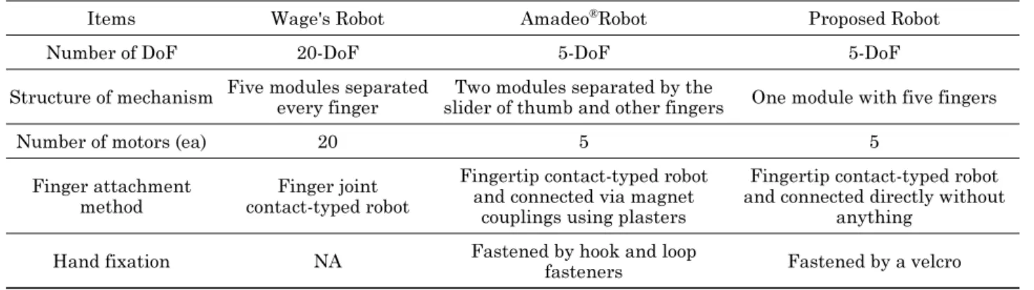