송전선로 Stockbridge Damper 진동특성 분석
Vibration Characteristics of Stockbridge Damper for Transmission Line
박 수 만*ꞏ 송 오 섭† Sooman Park* and Ohseop Song†
(Received May 3, 2018 ; Revised June 25, 2018 ; Accepted June 28, 2018)
Key Words : Stockbridge Damper(스톡브리지 댐퍼), Aeolian Vibration(풍성 진동), Transmission Line(송전선 로), Vibration Characteristic(진동특성), Natural Frequency(고유진동수)
ABSTRACT
Aeolian vibration, the cyclic conductor motions of overhead transmission lines, is wind-induced due to the shedding of vortices, and causes damages that negatively affect the service life of the overhead transmission lines. Generally, Aeolian vibration occurs in the range of 3 Hz ~ 150 Hz when the wind of 1 m/s ~ 7 m/s meets the transmission lines. Since Stockbridge dampers are used to sup- press Aeolian vibrations on overhead transmission lines, it is necessary to control the vibration per- formance of the Stockbridge damper that absorbs energy caused by the vibration. This paper per- forms dynamic characteristics and harmonic response analysis of the Stockbridge damper by mass variations of metal weights and length variations of messenger cable, and presents the influence of parameters reducing the vibration analyzed for each case.
1)
1. 서 론
가공송전선로에서 바람에 의해 발생하는 주된 진 동은 aeolian 진동, sub span 진동, galloping 진동, sleet jump 등으로 분류한다. 그 중 전력선에 작용 하는 바람에 의한 aeolian 진동을 저감시키기 위해 스톡브리지 댐퍼를 사용하고 있다(1~8).
송전선에 많이 사용되고 있는 스톡브리지 댐퍼는 1 m/s ~ 7 m/s 미풍구간에서 vortex shedding 현상에 의해 바람과 직각 방향으로 3 Hz ~ 150 Hz 영역에서 발생하는 풍진동을 효과적으로 저감하는 장치이다.
스톡브리지 댐퍼의 진동성능을 확보하고, 효율을 높 여서 송전선로의 풍진동으로 발생하는 에너지를 흡
수함과 동시에 송전선로의 진동을 저감시키는 것이
필요하다(1~13). 일반적으로 송전선로의 경간은 300 m
~ 450 m, 고유진동수는 0.1 Hz ~ 0.2 Hz 범위이고 국 내에 설치된 스톡브리지 댐퍼의 공진점은 15 Hz 미 만에서 발생하고 있다(9,10,14).
이 논문에서는 스톡브리지 댐퍼의 messenger cable 의 길이 및 댐퍼 양단의 metal weight의 질량 변화를 줄때 송전선의 진동에너지 흡수에 미치는 영향을 확 인하기 위해 스톡브리지 댐퍼에 대한 동특성해석과 그 결과를 토대로 조화응답해석을 수행하였다(9,10).
2. Stockbridge Damper의 3차원 모델 보통 다수의 부품으로 구성된 조립체는 해석모델
Corresponding Author; Member, Dept. of Mechanical Engineering at Chungnam National University
E-mail: [email protected]
* Member, Korea Electric Power Research Institute
Recommended by Editor Hyung Jo Jung
The Korean Society for Noise and Vibration Engineering
Fig. 3 FEM model of stockbridge damper
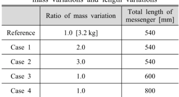
Ratio of mass variation Total length of messenger [mm]
Reference 1.0 [3.2 kg] 540
Case 1 2.0 540
Case 2 3.0 540
Case 3 1.0 600
Case 4 1.0 800
Table 1 Stockbridge damper model according to mass variations and length variations
Fig. 1 Stockbridge damper
Fig. 2 3-D Model of stockbridge damper 치수를 실측하여 모델링한다.
스톡브리지 댐퍼는 metal weight, galvanized steel messenger cable 및 aluminum vise clamp로 이루어 진 조립체이다. 따라서, 따라서 댐퍼의 실제 모델에 대한 진동특성평가를 위해 실제 사용하는 모델을 실 측하여 3차원 모델을 작성하였다. Fig. 1에는 스톡브
선로의 진동은 고주파의 주기적인 진동을 하고 있으 므로 작은 진폭에도 큰 영향을 받을 수 있다. 따라 서 스톡브리지 댐퍼와 같은 진동진폭 저감 장치를 사용한다. 스톡브리지 댐퍼는 전선의 지지점에서의 bending stress를 줄이기 위해 지지점 부근에 설치되 는 것이 일반적이다.
스톡브리지 댐퍼 양단의 무게 및 messenger ca- ble의 길이에 따른 진동특성의 변화를 검토하기 위 해 Table 1와 같이 양단의 총 무게 및 전체 길이의 변화를 고려하여 해석모델을 작성하였다.
3. 댐퍼의 유한해석 모델
스톡브리지 댐퍼의 3차원 모델을 토대로 해석을 수행하기 위해 유한요소 모델을 작성하였다. 해석모 델은 상용 유한요소 해석 프로그램인 ANSYS를 사 용하였으며, 스톡브리지 댐퍼에 대한 유한요소 해석 모델을 Fig. 3에 나타내었다. 이 댐퍼의 해석모델은 8절점 3차원 구조해석용 요소인 SOLID185를 주요 소로 사용하여 모델링하였다.
이 댐퍼는 송전선로에 aluminum vise clamp와 bolt로 연결되어 있다. Clamp와 bolt 연결부의 유한 요소 해석모델을 Fig. 4에 나타내었고, 댐퍼의 구성 품 중 에너지 소산에 가장 큰 영향을 미치는 부품인 metal weight와 messenger cable의 유한요소 해석모
Fig. 4 Aluminum vise clamp & bolt
Fig. 5 Metal weight
Horizon mode [Hz] Vertical mode [Hz]
Reference 13.468 13.544
Case 1
(X2.0) 9.524 9.577
Case 2
(X3.0) 7.776 7.820
Table 2 Vibration nature for damper model accord- ing to mass variation
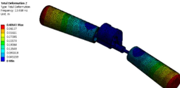
Fig. 6 Frequency mode of horizon direction (reference case, 13.468 Hz/1st mode)
Fig. 7 Frequency mode of vertical direction (reference case, 13.544 Hz/1st mode)
델을 Fig. 5에 나타내었다. 댐퍼의 질량은 metal weight의 mass만 고려하였고, messenger cable은 강 성과 감쇠 기능만 한다고 가정하고 기존 연구(3,4,8) 등에서 실험적으로 얻은 관계식을 적용하여 해석모 델을 작성하였다. Cable 강성은 개별 소선을 단일 rod형태로 등가강성화하여 적용하였다. 댐퍼는 송전 선로에 클램프로 결속되어 있어, 해석모델을 작성하 기 위해 접촉되어 있는 부분은 결속조건(bonded condition)을 적용하였다. 실제 설치된 스톡브리지 댐퍼는 철탑사이의 긴 송전선로에 의해 강체모드와 같은 거동을 갖지만 스톡브리지 자체의 동적특성을 파악하기 위해서 클램프의 접촉면을 고정조건으로 정의하고 경계조건을 적용하였다.
4. 동특성 해석
스톡브리지 댐퍼에 대한 유한요소 해석 모델을 토대로 감쇠가 없는 시스템을 구성하여 모드해석을 수행하였다. 댐퍼의 선로 수평 및 수직방향으로의 진동특성평가를 위해 클램프의 내부면에 대한 자유 도를 구속하여 모드를 추출하였다.
Figs. 6, 7은 스톡브리지 댐퍼 기준모델(무게 3.2 kg, 길이 540 mm)의 수평(F-R) 및 수직방향의 1차 진동 모드이며 고유진동수는 각각 13.468 Hz, 13.544 Hz이 다. 1차 모드의 고유진동수는 댐퍼의 공진점으로 바람 에 의해 송전선로에 저장된 에너지를 진동으로 소산하 는데 큰 영향을 미치는 주요 모드라고 할 수 있다.
기준모델의 댐퍼 해석모델을 기준으로 metal weight의 mass를 각각 2배, 3배 증가시켜 얻은 댐 퍼의 진동특성은 Table 2와 같고, 이에 대해 진동모 드를 계산하였다.
Figs. 8, 9는 mass를 3배 증가시켰을 때의 진동 모
Fig. 8 Frequency mode of horizon direction (3 times metal weight, 7.776 Hz/1st mode)
Fig. 9 Frequency mode of vertical direction (3 times metal weight, 7.820 Hz/1st mode)
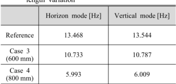
Horizon mode [Hz] Vertical mode [Hz]
Reference 13.468 13.544
Case 3
(600 mm) 10.733 10.787
Case 4
(800 mm) 5.993 6.009
Table 3 Vibration nature for damper model according to length variation
Fig. 10 Frequency mode of horizon direction (messenger cable length 600 mm, 10.733 Hz
/1st mode)
Fig. 11 Frequency mode of vertical direction (messenger cable length 600 mm, 10.787 Hz
/1st mode)
드이며, 댐퍼의 mass를 기준모델 대비 증가할수록 고유진동수의 감소폭이 커지는 것으로 나타났다. 그 리고, messenger cable의 길이를 각각 600 mm, 800 mm 증가시켜 얻은 댐퍼의 진동특성은 Table 3과 같고, 이의 진동모드를 계산하였다. Figs. 10, 11은 길이를 600 mm로 늘렸을 때의 진동 모드이며, mes- senger cable의 길이를 기준모델 대비 증가할수록 고유진동수의 감소폭이 커지는 것으로 나타났다.
5. 무게와 길이 변화에 따른 조화응답 해석 스톡브리지 댐퍼에 대한 동특성해석을 수행한 결
과를 토대로 조화응답해석을 수행하였다. 가진력은 송전선에 작용하는 바람에 의한 공력을 조화 진동 조건으로 metal weight의 끝단의 질량중심점에 단위 하중(1N), 0 Hz ~ 50 Hz의 범위로 적용하였다.
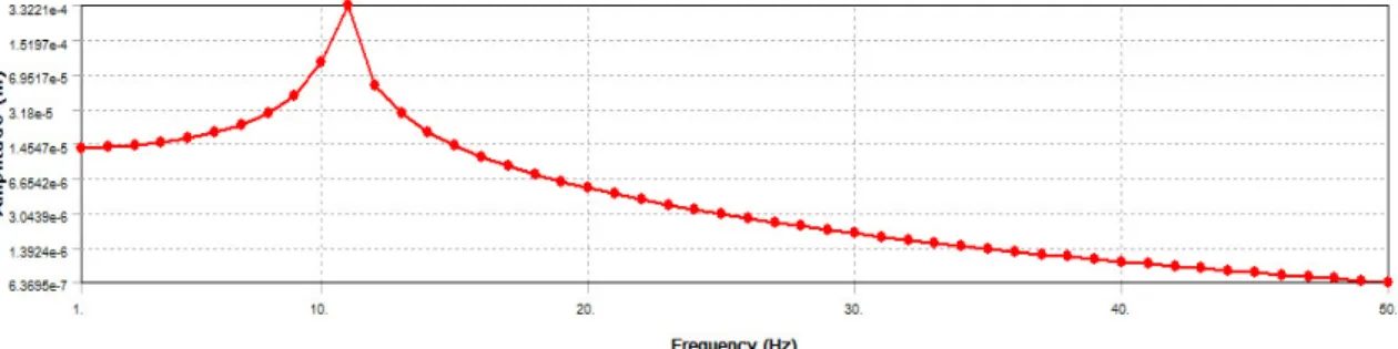
댐퍼의 metal weight의 mass 변화와 messenger cable의 길이 변화에 따른 진동특성의 관계를 확인하 기 위하여 조화응답해석을 수행하였다. Fig. 12는 기 준모델의 응답 특성이고, Fig. 13은 metal weight의 mass를 2배 증가시켰을 경우의 응답이고, Fig. 14는 messenger cable의 길이를 각각 600 mm로 변화시켰 을 때의 응답을 나타내었다.
해석결과, mass가 늘어나는 경우 즉 고유진동수가 감소하는 경우일수록 진동진폭의 상대적인 크기는 줄어들고, 길이가 길어지는 경우에는 진동진폭의 상 대적인 크기가 커지는 것을 알 수 있다. 따라서, 송 전선에 작용하는 풍압에 의한 진동은 송전선의 길이, 경계조건에 의하여 주파수가 결정되므로 이 주파수 에 의한 반복 하중의 저감을 위해서는 댐퍼의 mass 와 messenger cable 길이를 적절히 조절하여 고유진 동수를 튜닝함으로써 진동을 저감할 수 있다.
Fig. 12 Displacement of damper’s Vert. direction for reference model (Max. Amp. = 1.132E-4)
Fig. 13 Displacement of damper’s Vert. direction (2 times mass, Max. Amp. = 8.6E-5)
Fig. 14 Displacement of damper’s Vert. direction (messenger length 600 mm, Max. Amp. = 3.322E-4) 6. 결 론
스톡브리지 댐퍼는 바람에 의해 흔들리는 송전선 이 받은 에너지를 흡수하고, 댐퍼의 양 끝단의 met- al weight가 진동함으로써 에너지를 소산하고 시스 템의 진동진폭을 감소시키는 장치이다. 송전시스템 의 진동진폭을 감소시키기 위해서는 다양한 바람의 성분에 따른 댐퍼의 동적인 응답을 예측해야 한다.
이에 스톡브리지 댐퍼의 양 끝단 metal weight의 mass를 변화시키는 경우와 messenger cable의 길이 를 증가시켰을 때 동특성 해석과 그 결과를 토대로 조화응답해석을 수행하였다. 동특성 해석결과, mass
에 의한 수평, 수직방향의 고유진동수는 mass가 증 가함에 따라 작아졌으며, messenger 길이를 증가시 킬수록 고유진동수가 작아지는 것을 확인할 수 있었 다. 조화응답해석 결과, 양 끝단의 metal weight의 mass가 2배, 3배로 늘어나는 경우 즉 고유진동수가 감소하는 경우일수록 진동진폭의 상대적인 크기(기 준모델 > Case 1 > Case 2)는 줄어들고, messenger cable의 길이 변화시 길이가 길어질수록 진동진폭의 상대적인 크기(Case 4 > Case 3 > 기준모델)는 커지 는 것을 알 수 있었다.
일반적으로 철탑과 철탑사이의 스팬 길이가 증가 하면 송전선로의 고유진동수는 감소하고, 애자형이
이 연구는 한국전력공사의 재원으로 전력연구원 2014년 주력연구개발과제로 지원을 받아 수행된 것 임(과제번호 : R14TA02).
References
(1) Chan, J., 2006, EPRI Transmission Line Reference Book: Wind-Induced Conductor Motion, EPRI.
(2) Kiessling, F., Nefzger, P., Nolasco, J. F. and Kaintzyk, U., 2003, Overhead Power Line: Planning, Design, Construction, Springer, Berlin; New-York, pp.
323~340.
(3) Barbieri, N., 2012, Dynamic Analysis of Stockbridge Damper, Advances in Acoustics and Vibration, Vol. 2012., Article ID 659398, DOI: 10.1155/2012/659398.
(4) Canales, C. N., López, A. L., Venegas, J. C., Razo-Garcia, J. and Aguilera-Cortés, L. A., 2008, Optimal Design of Stockbridge Dampers, Ingenieria Mecanica, Vol. 2, No. 2, pp. 193~199.
(5) Kasap, H., 2012, Investigation of Stockbridge Damper for Vibration Control of Overhead Transmission Lines, Middle East Technical University, Ankara.
(6) Kim, C. J., 2016, Determination of Design Parameters of Stockbridge Damper, Transactions of the Korean Society for Noise and Vibration Engineering, Vol. 26, No. 7, pp. 814~819.
(7) Vaja, N. K., Barry, O. and DeJong, B., 2017, Finite Element Modeling of Stockbridge Damper and Vibration Analysis: Equivalent Cable Stiffness, International Journal of Aerospace and Mechanical Engineering, Vol. 11, No. 6, pp. 1190~1194.
(8) Claren, R. and Diana, G., 1969, Mathematical Analysis of Transmission Line Vibration, IEEE Transaction on Power Apparatus and Systems, Vol. 88, No. 12, pp. 1741~1771.
Corporation, pp. 142~198.
(11) Tian, L. and Zeng, Y., 2016, Parametric Study of Tuned Mass Dampers for Long Span Transmission Tower-line System under Wind Loads, Shock and Vibration, Vol. 2016, Article ID 4965056, DOI:
10.1155/2016/4965056.
(12) Kalombo, R. B., Loubser, R. and Moodley, P., 2012, Bending Stress of Stockbridge Damper Messenger Cable: Experimental Data and Modelling, Presented at 18th World Conference on Nondestructive Testing
(13) Lara-Lόpez, A. and Colín-Venegas, J., 2001, Endurance of dampers for electric conductor, International Journal of Fatigue, Vol. 23, pp. 21~28.
(14) Kim, C., Ryu, E., Jang, S., Keum, E., Lee, C.
and Choi, S., 2017, Study on Dynamic Characteristics of Stockbridge-type Damper Installed in South Korea, 2017 Joint Conference by KSNVE, ASK and KSME, p. 418.
Sooman Park received his B.S. degree in the Department of Mechanical Engineering in Hanyang University in 1987. His M.S. degree was awarded by Chungnam National University. He is currently a chief researcher at KEPCO Research Institute, Korea.
Ohseop Song received B.S. degree from the Dept. of Mechanical Design Engineering at Seoul National University. His Ph.D. degree was awarded by Virginia Polytechnic Institute & State University. He is cur- rently a professor in the Dept. of Mechanical Engineering at Chungnam National University, Daejeon, Korea.