서론 I.
, , ,
.
(motion detection) .
.
, .
[1,2].
. 3
,
.
(RFID, Vision )
,
[3].
[4,5]
* (Corresponding Author)
: 2010. 3. 5., : 2010. 6. 1., : 2010. 9. 30.
, , :
([email protected]/[email protected]/[email protected])
2010 .
[6].
.
3 1
. 3
3 .
,
,
[7-9].
.
,
, .
, .
, , .
, .
.
Foot Movement Tracking System using Ultrasonic Sensors and Inertial Sensors
, ,
*(Jang Hun Boo1, Sang Kyeong Park1, and Young Soo Suh1)
1Univ. of Ulsan
Abstract: This paper presents a foot movement tracking system using ultrasonic sensors and inertial sensors, where the position and velocity of foot are computed using inertial sensors and ultrasonic sensors mounted on a shoe. A foot movement can be estimated using an inertial navigation algorithm only; however, the error tends to increase due to biases of gyroscopes and accelerometers. To reduce the error, a localization system using ultrasonic sensors is additionally used. In the localization system using ultrasonic sensors, the position is continuously calculated in the absolute coordinate. An indirect Kalman filter is used to combine inertial sensors and ultrasonic sensors. Through experiments, it is shown that the proposed system can track a foot movement.
Keywords: ultrasonic sensors, inertial sensors, motion tracking, Kalman filter, inertial navigation algorithm
Copyright© ICROS 2010
시스템구성 II.
,
.
2 . 2
.
,
.
, .
,
[7-9]
,
.
1 (
MCU1, MCU2). MCU1 .
,
. MCU2
3
,
. MCU1 MCU2
3 .
움직임 추적 III.
초음파센서를 이용한 차원 위치 추정
1. 2
,
, .
3
.
. 2
2 . 2
, ,
( ) ,
.
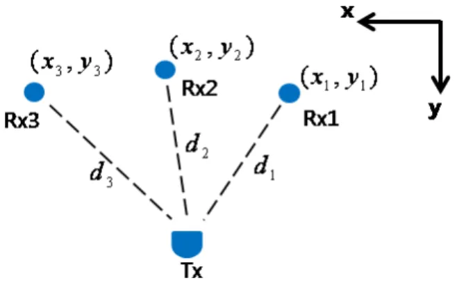
, (Tx)
.
3 .
3 Rx1 Rx2, Rx2
Rx3, Rx3 Rx1 3
. (Tx)
3(Rx1,Rx2,Rx3) (
,
), (
,
), (
,
) .
(1) (2)
. (1)
(2)
(3) (y > 0) .
,
,
,
.
(
) .
관성센서를 이용한 차원 궤적 추정
2. 3
3 , ,
, , ,
1. . .
Fig. 1. System overview.
2. .
Fig. 2. Estimation system using ultrasonic sensors.
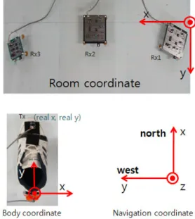
.
3
. 3
. (body coordinate)
. (room coordinate) 3
. (navigation coordinate)
, .
.
.
(4)
관성항법알고리즘 IV.
관성항법알고리즘 1.
[4]
.
(4) .
.
( ) .
,
,
,
,
.
∙ ∈×:
∙ ∈×:
∙ ∈×:
∙ ∈× :
∙ ∈× :
∙ ∈× :
∙ ∈× :
∙ ∈× :
∙ ∈× :
∙ ∈× :
∙ ∈× :
.
(5)
≜
.
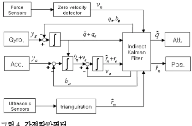
(6) 간접칼만필터2.
(6)
,
(5) (7)
.
(7)
⊗ ,
.
≈
∈× (8)
(7) (5)
.
3. .
FIg. 3. Coordinate definition.
(9)
(9)
≠ , ≠, ≠ ,
.
≜
≜ (10)
, , ,
(8) (10) , ,
.
.
∈× (11)
.
(12)
, ( ) .
,
(12)
.
4 .
영속도 보정 3.
4 (, ,
) (, )
. 0
,
0 .
.
.
,
[5].
.
0 ,
, ( ) () ( )
. (FlexiForce A201)
. 실험 V.
초음파센서테스트 1.
T/R40-16 10Hz MCU1
. 1000 4 5m~
, .
200 ,
2.5m .
1 1 200
.
1
,
.
4. .
Fig. 4. Indirect kalman filter.
.
.
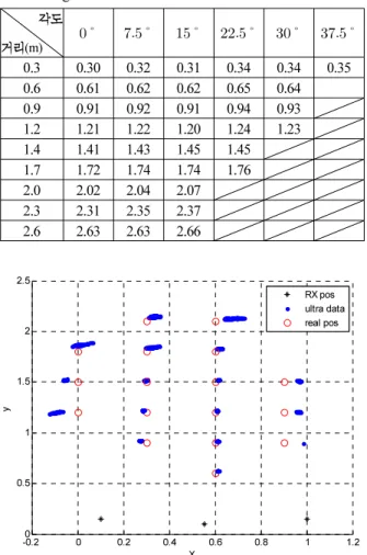
5 2 (Tx)
(Rx1~3)
x , y 30㎝
. (0.54, 1.60)
5 x
(Rx2) x=0.54
. 5
,
0.3~1.0m, 0.6~2.3m .
2 2
, 3 RMS .
x 0.3 0.6m, y~
1.2 1.5m~ 0.02m
. 관성센서테스트
2.
Xsens
MTi . 100Hz
. x 0.3 0.6m,~
y 1.2~1.5m ,
(0.6, 1.5) (0.6,1.2), (0.3,1.2),
(0.3, 1.5) 1
. 6-7
. 6
1.
Table 1. Distance measurements with different ultrasonic sensor angles.
(m)
0.3 0.30 0.32 0.31 0.34 0.34 0.35 0.6 0.61 0.62 0.62 0.65 0.64 0.9 0.91 0.92 0.91 0.94 0.93 1.2 1.21 1.22 1.20 1.24 1.23 1.4 1.41 1.43 1.45 1.45 1.7 1.72 1.74 1.74 1.76 2.0 2.02 2.04 2.07 2.3 2.31 2.35 2.37 2.6 2.63 2.63 2.66
-0.20 0 0.2 0.4 0.6 0.8 1 1.2
0.5 1 1.5 2 2.5
X y
RX pos ultra data real pos
5. 2 .
Fig. 5. 2D estimation using only ultrasonic sensors.
2. .
Table 2. Means of 2D estimation results.
2.1 (0.33, 2.15) (0.67, 2.13) 1.8 (0.01, 1.87) (0.32, 1.84) (0.62, 1.83)
1.5 (-0.05, 1.52) (0.29, 1.52) (0.61, 1.52) (0.96, 1.51) 1.2 (-0.09, 1.20) (0.28, 1.22) (0.60, 1.22) (0.96, 1.21) 0.9 (0.27, 0.92) (0.61, 0.92) (0.98, 0.90)
0.6 (0.61, 0.63)
y(m)
x(m) 0 0.3 0.6 0.9
3. RMS.
Table 3. RMS values of 2D estimation results.
2.1 0.0583 0.0762
1.8 0.0707 0.0447 0.0361
1.5 0.0539 0.0224 0.0224 0.0608
1.2 0.0900 0.0283 0.0200 0.0608
0.9 0.0361 0.0224 0.0800
0.6 0.0316
y(m) x(m)
0 0.3 0.6 0.9
0.1 0.2 0.3 0.4 0.5 0.6 0.7 0.8
1.1 1.2 1.3 1.4 1.5 1.6 1.7 1.8
X Y plane (room coordinate)
X (m) Y (m
)
6.
( ).Fig. 6. plane ( Result only using inertial sensors).
2 , 7
.
6-7
.
. 7
. 항법알고리즘 시뮬레이션 3.
. 1 , 1
1m . 8
.
1m,
(11). 9-10
. 10 A C
. 3
0.02 .
10 A
2 , B
. C
.
초음파센서와 관성센서를이용한 차원 움직임 추정
4. 3
100Hz 10Hz
. 10-11
, 10
.
, 10Hz
. 12
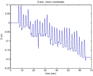
0 10 20 30 40 50 60 70
-0.25 -0.2 -0.15 -0.1 -0.05 0 0.05
0.1 Z axis (room coordinate)
time (sec) Z (m
)
7.
( ).Fig. 7. axis ( Result only using inertial sensors).
0 0.5 1 1.5 2 2.5 3
-0.5 0 0.5 1 1.5
time(sec) real p
ositio
n (m) X axis pos
Y axis pos Z axis pos
8. .
Fig. 8. Simulation model's positions according to the time.
0 0.2
0.4 0.6
0.8 1 -0.2 -0.1 0 0.1 0.2 0
0.1 0.2 0.3 0.4 0.5
Y (m) X (m)
Z (m )
real pos estimated pos
9. 3 .
Fig. 9. 3D movement tracking simulation.
0 0.5 1 1.5 2 2.5 3
0 0.01 0.02 0.03 0.04 0.05 0.06 0.07 0.08 0.09
time (sec) error
(m)
A B C
10. .
Fig. 10. The position error on the simulation.
.
(0.6, 1.5, 0) y
,
. 13 , 14
. 13 a
, b
.
a b
. b
(0.82, 1.71, -0.08) a 0.31m
. 14 6
7.8 . 2
0.31m
. b
.
13 b a
. 결론 VI.
. 0.2 0.25 0.3 0.35 0.4 0.45 0.5 0.55 0.6 0.65 0.7
1.1 1.15 1.2 1.25 1.3 1.35 1.4 1.45 1.5 1.55
1.6 X Y plane (room coordinate)
X (m) Y (m
)
10.
( + ).Fig. 10. plane ( inertial sensors and ultrasonic sensors.
0 10 20 30 40 50 60 70
-0.08 -0.06 -0.04 -0.02 0 0.02 0.04 0.06 0.08 0.1
0.12 Z axis (room coordinate)
time (sec) Z (m
)
11.
( + ).Fig. 11.axis (inertial sensors and ultrasonic sensors).
0.3 0.4 0.5 0.6 1.2
1.3 1.4 1.5 1.6 -0.05
0 0.05 0.1
X (m) Y (m)
Z (m )
12. .
Fig. 12. 3D Foot movement tracking.
0.6 0.7 0.8 0.6
0.8 1 1.2 1.4 1.6 0 0.1 0.2 0.3
X (m) Y (m)
Z (m )
a b
13. .
Fig. 13. 3D Foot movement tracking.
14. .
Fig. 14. Velocity from the inertial sensor.
0 2 4 6 8 10 12
-3 -2 -1 0 1 2 3
time (sec) veloc
ity (m /s)
.
,
. 9 z
.
.
,
3 .
.
참고문헌
[1] K. Yokoi, M. Niituma, and H. Hashimoto, “Localization of human hand by using inertial sensors,” Proc. of SICE Anual Conference 2008, pp. 1818-1822, 2008.
[2] L. Gan, S. Lik-kwan, and Z. Ulrike, “Dynamic hand gesture tracking and recognition for real-time immersive virtual object manipulation,” Proc. of 2009 Ineternational Conference on Cyber Worlds, pp. 29-35, 2009.
[3] L. Cheng and S. Hailes, “On-Body wireless inertial sens- ing foot control applications,” Proc. of IEEE 19th International Symposium, pp. 1-5, 2008.
[4] S. K. Park and Y. S. Suh, “Gait state classification by HMMS for pedestrian inertial navigation system,” Proc.
of KIEE Journal, vol. 58, no. 5, pp. 1010-1018, May 2009.
[5] L. Ojeda and J. Borenstein, “Personal dead-reckoning system for GPS-denied environments,” Proc. of IEEE International Workshop, pp. 1-6, 2007.
[6] S. K. park, Y. S. Suh, and D. T. Nhut, “The pedestrian navigation system using vision and inertial sensors,”
Proc. of ICCAS-SICE International conference, pp.
3970-3974, 2009.
[7] J. J. Park, D. H. Lee, S. Y. Kim and Y. S. Mun, “A study on the recognizing range expansion techniques of the ultrasonic location awareness system for the ubiq- uitous computing,” Proc. of KICS Journal, vol. 31, no.
7B, pp. 595-601, Jul. 2006.
[8] S. S. Lee, M. G. Choi, J. H. Park and J. M. Lee,
“Localization of a high-speed mobile robot using Ultrasonic/RF sensor and global features,” Journal of Institute of Control, Robotics and Systems, vol. 15, no.
7, pp. 734-741, Jul. 2009.
[9] U. L. Hwang, K. S. Jung and D. H. Shin, “Position er- ror due to distance error in the localization system using Ultrasonic,” Proc. of KSME Conference 2007, pp. 2837- 2842, May 2007.
부 장 훈 2009
. 2009 ~ .
.
박 상 경 2002
. 2004 . 2006 ~
. .
서 영 수
1990 .
1992 . 1997
. 2000 ~
. .