***†김병탁(교신저자) : 부경대학교 기계설계공학과 E-mail : [email protected], Tel : 051-629-6161
*이민영 : 부경대학교 대학원 기계설계공학과
**† Kim Byung-Tak(corresponding author) : Department of Mechanical Design Engineering, Pukyong National University E-mail : [email protected], Tel : +82-51-629-6161 *Lee Min-Young : Graduated school of Mechanical Design
Engineering, Pukyong National University
A Study on the Contact Characteristics of Metal Ring Joint Gaskets
Lee Min-Young* and Kim Byung-Tak**†
(Received 19 January 2016; Accepted 13 June 2016)
Abstract : Gaskets are usually used for the sealing of flange joints. The joint is usually composed of two flanges, a ring gasket and clamping bolts. The metal ring gasket is suitable for pipe flanges, pumps and valve joints in high temperature and high pressure environments. A very high surface stress is developed between a ring type joint gasket and the flange groove when the ring type joint is bolted up in a flange. The dimensions of flanges and ring joint gaskets for the pipe sizes that are in common use are specified in the ANSI codes. However, sometimes it is necessary to make a new design for the flange joint which is not specified in the codes, as the equipment is getting larger and larger in size. This paper presents the contact behavior of Class 600 ring joint gaskets with oval and octagonal cross sections. Five different sizes of gaskets are employed in the analysis, and one of them is newly designed on the basis of analysis results obtained from existing models. Three load steps are used to find the stress, stain and contact pressure etc., and to compare the contact characteristics among the models due to the bolt clamping force and the working surface pressure. ANSYS Workbench version15 is used to conduct the finite element analysis.
Key Words : Finite Element Analysis, Metal Ring Gasket, Contact Characteristics, Bolt Pretension Performance
1. Introduction
A flange joint is a connection of pipes, where the connecting pieces have flanges by which the parts are bolted together. In order to prevent leakage, various types of gaskets are available depending upon their construction,
materials and features. The types of gaskets commonly used are non-metallic gaskets, spiral-wound gaskets and ring joint gaskets[1-3].
The ring joint gasket is suitable for pipe flanges, pumps and valve joints in high temperature and high pressure environments.
Ring joint gaskets are used with ring type
[논문] 한국태양에너지학회 논문집 Journal of the Korean Solar Energy Society
Vol. 36, No. 3, 2016 IS S N 1 5 9 8 - 6 4 1 1 http://dx.doi.org/10.7836/kses.2016.36.3.025
joint flanges and are available in octagonal or oval cross sections. A very high surface stress is developed between a ring type joint gasket and the flange groove when the ring type joint is bolted up in a flange.
There are several studies related to the behavior characteristics of ring joint gaskets.
Since the performance of the flange joint is mainly characterized by its strength and sealing capability, these studies have focused on these two areas. Research[4-7] on the strength of the flange joint has been conducted to calculate the contact pressure of the gasket and the flange groove, which has a significant effect on the sealing capability, including the bolt load[8,9]. Also, studies on the sealing capability[10,11] were carried out to measure the leakage through experiments where the flange assembly was subjected to internal pressure in a given temperature. Since the contact pressure of the gasket exerts an extremely large effect on the sealing capability, these studies have also been carried out in a manner to perform the stress analysis using the finite element method.
This paper presents the contact behavior of Class 600 ring joint gaskets with oval and octagonal cross sections. Five different sizes of gaskets are employed in the analysis, and NPS 28ʺ has been newly designed on the basis of analysis results obtained from existing models. Three load steps are used to find the stress, stain and contact pressure etc., and to compare the contact characteristics among the models due to the bolt clamping
force and the working surface pressure. The commercial software, ANSYS Workbench release15, is used to conduct the finite element analysis.
2. Finite element analysis
The geometry of the flange joint with NPS 6ʺ is illustrated by example in Fig. 1, which falls under a category of ANSI B16.5 Class 600, which is the rating class designation included in Flanges and Flanged Fittings Standard. The joint is composed of two flanges, a ring gasket, and twelve bolts.
Since the joint has a geometrical symmetry in circumferential direction, the finite element model in this case can be constructed using only 1/12 portion of the whole region.
However, for different models, the portion to be modeled must be altered according to the number of bolts. In this study, five different models are used to find the contact behaviors of Class 600 ring joint gaskets. In particular, the clamping bolts are included in the model, and bolt pretension loads are applied to the assembly as a real installation.
Fig. 1 Geometry of the flange joint (NPS 6ʺ, octagonal type)
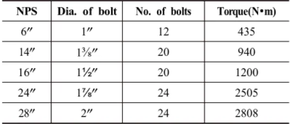
The models employed in this study are summarized in Table 1. In the table, the NPS 28ʺ is not specified in the ANSI codes. The dimensions and the torque of the model NPS 28ʺ are estimated through the process of curve fitting from the specified data of existing models.
NPS Dia. of bolt No. of bolts Torque(N•m)
6ʺ 1ʺ 12 435
14ʺ 1
⅜
ʺ 20 94016ʺ 1½ʺ 20 1200
24ʺ 1⅞ʺ 24 2505
28ʺ 2ʺ 24 2808
Table 1. Models used in the analysis
As an example, the finite element model and applied boundary condition for Class 600 NPS 24ʺ with octagonal cross section are shown in Fig. 2 and Fig. 3 respectively. In this case, only 1/24 portion of the whole model is included in the finite element model.
The frictionless support means the symmetric face, on which the displacement is restrained in the perpendicular directions of the face.
The frictionless condition is applied on the contact region between the flange groove and the ring gasket. The bolt pretension load is computed from the tightening torque by the following[12]
where T is the tightening torque, p is the pitch, d is the major diameter, μ1 is the friction coefficient between the bolt and nut, μ2 is the collar friction and dm is the mean collar diameter.
In the case of the NPS 24ʺ, twenty-four bolts with 1⅞ʺ major diameter are employed
and the calculated pretension load of each bolt is 102.66 kN.
Fig. 2 Finite element model of the NPS 24ʺ with octagonal cross section
Fig. 3 Applied boundary conditions for the NPS 24ʺ with octagonal cross section
The working surface pressure(600 psi) is applied on the inner surfaces only at load
(1) μ2 0.50dm μ1
0.583d 0.161p
F T
´ +
´
= +
step 3, that is, no pressure is applied at load step 1(bolt pretension load) or load step 2(lock). Also, the vertical displacement on the middle plane of the ring gasket is restrained to prevent rigid body motion.
The materials of the flange and the ring gasket are stainless steel (SUS304) and carbon steel (SS347), respectively. Table 2 shows the mechanical properties of the two materials.
Parameters SUS304 SS347 Young’s modulus 193 GPa 195GPa
Poisson’s ratio 0.29 0.27
Yield strength 215 MPa 205 MPa Tangent modulus 1.8 GPa 1.45 GPa
Table 2. Mechanical properties of materials
3. Results and discussion
Fig 4 represents the stress distributions of the NPS 24ʺ flange joint with oval cross section at load step 1 and load step 3. The maximum stress at load step 1 is developed on the contact region, and the value is 398 MPa.
However, the value at load step 3 is decreased by 9 MPa due to the working fluid pressure.
(a) load step 1(bolt pretension load)
(b) load step 3(pressure load) Fig. 4 Stress distributions of flange joint
(oval type, NPS 24ʺ)
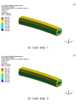
(a) load step 1
(b) load step 3
Fig. 5 Stress distributions of ring gasket (octagonal type, NPS 24ʺ)
The stress distributions of the gasket of the NPS 24ʺ with octagonal cross section at two load steps are shown in Fig. 5. Due to the symmetric geometry and loading, the stress contour is shown to also be symmetric with respect to the symmetric planes. The figure reveals that the stress variation along the circumferential direction of the gasket is nearly uniform even if the clamping force intensity is not uniformly distributed in that direction. Analogous to the oval ring gasket, the maximum stress level is decreased by 14 MPa after the fluid pressure acts upon the inner surface of the model. Also, the maximum stress value of the octagonal model is much less than that of the oval model by over 100 MPa. In the cases of other models with different
nominal pipe sizes, the same phenomenon is observed. These results can be expected from the fact that there is a difference of contact area between two models while the same bolt pretension load is applied on the contact region.
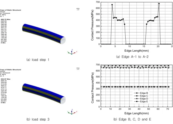
Fig. 6 shows the contact pressure of the NPS 28ʺ flange joint with oval cross section at load step 1 and load step 3. The contact pressure shown is nearly uniform in the longitudinal direction and is symmetric with respect to the mid-plane of the gasket, but there is a sharp change in magnitude along the circumferential direction.
(a) load step 1
(b) load step 3
Fig. 6 Contact pressure of ring gasket (oval type, NPS 28ʺ)
The variations of contact pressure along
the contact edges shown in Fig. 7 are represented in Fig. 8, for the case of the NPS 16ʺ by example, in order to examine the contact length and the pressure magnitude.
Fig. 7 Reference edges to check contact pressure
0 5 10 15 20 25
0 100 200 300 400 500 600 700
Contact Pressure(MPa)
Edge Length(mm) (a) Edge A-1 to A-2
0 10 20 30 40 50 60 70
0 100 200 300 400 500 600 700
Edge B Edge C Edge D Edge E
Contact Pressure(MPa)
Edge Length(mm) (b) Edge B, C, D and E
Fig. 8 Variation of contact pressure along the reference edges of ring
The results reveal that the contact region
along edge A is limited to the inclined part of the edge and that two peak pressures appear at the ends of edge B and E. The contact pressures along edge C and D are perfectly the same in magnitudes and have no variations in circumferential direction. On the other hand, the contact pressures along edge B and E are much higher than those of edge C and D, but have negligible variations in circumferential direction.
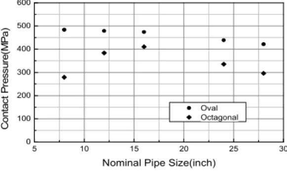
Fig. 9 shows the mean contact pressures on the contact surfaces of the ring gaskets with various nominal pipe sizes and cross sections. For all of the models, the maximum contact pressure of the oval type ring gasket is higher than that of the octagonal type ring gasket, because of the difference of the contact surface area. However, the octagonal type gasket, which has a relatively large contact area, is supposed to be more reliable from the contact stability point of view.
5 10 15 20 25 30
0 100 200 300 400 500 600
Contact Pressure(MPa)
Nominal Pipe Size(inch) Oval Octagonal
Fig. 9 Mean contact pressures for various nominal pipe sizes
4. Conclusions
In this study, the contact behavior of Class 600 ring joint gaskets with oval and octagonal
cross sections is analyzed with the finite element method. The results are summarized as follows.
(1) The stress variation in the circumferential direction of the gasket is nearly uniform even if the clamping force intensity is not uniformly distributed in that direction.
(2) The maximum stress levels are slightly decreased after the fluid pressure acts upon the inner surfaces in both models (3) The maximum stress value of the octagonal model is much less than that of the oval model because of the difference in contact areas between the two models.
(4) The contact pressure is nearly uniform in the longitudinal direction and symmetric with respect to the mid-plane of the gasket, but there is a sharp change in magnitude along the circumferential direction.
Acknowledgement
This work was supported by a Research Grant of Pukyong National University(2015 year)
References