GPS Software 수신기의 분석
장위*ㆍ서희종**
Analysis of GPS Software Receiver
Wei Zhang
*ㆍHee-Jong Suh
**요 약
본 논문에서는 GPS 수신기에서 L1 C/A 신호의 포착과 추적을 이해하고, GPS 수신기 신호의 수신에 관해 서 연구하고, GPS 신호 수신과정에 관해서 Matlab을 사용해서 모의실험을 한다. 실험한 결과, 우리가 실행한 방법의 정확성과 가능성을 확인할 수 있었고, GPS 수신기의 성능은 위성의 수신능력이 매우 중요하다는 것을 알 수 있었다.
ABSTRACT
In this paper, we see the acquisition and tracking of L1 C/A signal on GPS receiver, do the research on GPS signal capture principle's foundation, and do the simulation of the GPS signals capture process for it’s realizing and analyzing by Matlab. The simulation result, we can confirm this method's accuracy and the feasibility, and see that a satellite receiving ability play an important role in the efficiency of receiver.
키워드
GPS, Software, GPS, Acquisition, Tracking, Matlab S/W, GPS, 포착, 추적, Matlab
* 북경석유화공학원(Email)
** 교신저자 : 전남대학교 전자통신공학과 ㆍ접 수 일 : 2017. 12. 13
ㆍ수정완료일 : 2018. 01. 14 ㆍ게재확정일 : 2018. 02. 15
ㆍReceived : Dec. 13, 2017, Revised : Jan. 14, 2018, Accepted : Feb. 15, 2018 ㆍCorresponding Author : Hee-Jong Suh
Dept. Electro. Comm. Eng, Chonnam National University Email : hjsuh@jnu.ac.kr
Ⅰ. INTRODUCTION
GPS (Global Positioning System) signal acquisition process is a two-dimensional (code and frequency) search in order to synchronize the GPS receiver replica code and the carrier frequency[1].
Traditionally, C/A(coarse acquisition) code can be quickly and easily acquired, and is used as a hand over for P-code acquisition[2]. GPS is a satellite- based navigation system. It is based on the computation of range from the receiver to multiple
satellites by multiplying the time delay that a GPS
signal needs to travel from the satellites to the
receiver by velocity of light. GPS has already been
used widely both in civilian and military
community for positioning, navigation, timing and
other position related applications. The system has
already proved it’s reliability, availability and good
accuracy for many applications[3-4]. In order to
track and decode the information in the GPS signal,
an acquisition method must be used to detect the
presence of the signal. Once the signal is detected,
http://dx.doi.org/10.13067/JKIECS.2018.13.1.229
the necessary parameters must be obtained and passed to a tracking program. From the tracking program information such as the navigation data can be obtained. The acquisition method must search over a frequency range of ±10 KHz to cover all of the expected Doppler frequency range for high-speed aircraft. In order to accomplish the search in a short time, the bandwidth of the searching program cannot be very narrow.
In this paper, we limit our discussion within the L1 band and C/A code only since L2 band and P code are used primarily for military purpose and the encryption codes are not available to the civilian community. We will explain briefly GPS signal structure and software-based GPS receiver architecture. The main focus of the paper is on how GPS signal can be processed by using acquisition and tracking algorithms to extract the navigation data bits from the raw data[5-7].
The remainder of this paper is organized as follows. In Section II the software GPS receiver are introduced. Section III includes signal acquisition module, signal simulation and implementation, Section IV is on the signal tracking module and signal simulation ; Section IV concludes this paper.
Ⅱ. SOFTWARE GPS RECEIVER
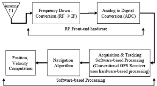
The architecture of software-based GPS receiver is as shown in Fig. 1. It consists of an antenna and a RF front-end devices, which are the only hardware devices of the system. The RF front-end device is necessary to down convert the GPS signal to an intermediate frequency (IF), sample the IF signal and digitize it. The present CPU capacity is still unable to process the GPS signal directly from the antenna in completely software-based approach. Thus a RF front-end device is still necessary. In conventional hardware-based GPS receiver, the lower three blocks in Fig. 1 are
implemented in an IC chip and hence the user does not have a free access to the algorithms built inside the chips. In software-based receiver, these blocks are fully implemented using high level programming languages and hence the user has complete control over the algorithms. This is the main difference between the software-based GPS receiver and a conventional hardware receiver. The front-end IF is 4.1304 MHz, sampling frequency is 16.368Mhz and four bits per sample.
Fig. 1 Architecture of software-based GPS receiver.
2.1 SIGNAL ACQUISITION MODULE
The GPS signal is combination of carrier wave, C/A code and navigation message. In order to extract the navigation message from the GPS signal, it is necessary to remove the carrier wave (demodulate) and the C/A code (de-spread). After, demodulation and de-spreading, we get only the navigation message and noise. These navigation messages are then interpreted based on the definitions or coding scheme provided in the interface control document (ICD) of GPS[1]. One common way to start an acquisition program is to search for satellites that are visible to the receiver.
If the rough location and the approximate time of
day are known, information is available on which
satellites are available, such as on some Internet
locations, or can be computed from a recently
recorded almanac broadcast. If one uses this
method for acquisition, only a few satellites (a
maximum of 11 satellites if the user is on the
earth’s surface) need to be searched. However, in case the wrong location or time is provided, the time to locate the satellites increases as the acquisition process may initially search for the wrong satellites[4].
The other method to search for the satellites is to perform acquisition on all the satellites in space; there are 24 of them. This method assumes that one knows which satellites are in space. If one does not even know which satellites are in space and there could be 32 possible satellites, the acquisition must be performed on all the satellites. This approach could be time consuming;
a fast acquisition process is always preferred. The conventional approach to perform signal acquisition is through hardware in the time domain. The acquisition is performed on the input data in a continuous manner. Once the signal is found, the information will immediately pass to the tracking hardware. In some receivers the acquisition can be performed on many satellites in parallel.
When a software receiver is used, the acquisition is usually performed on a block of data. When the desired signal is found, the information is passed on to the tracking program.
If the receiver is working in real time, the tracking program will work on data currently collected by the receiver. Therefore, there is a time elapse between the data used for acquisition and the data being tracked.
If the acquisition is slow, the time elapse is long and the information passed to the tracking program obtained from old data might be out-of-date. In other words, the receiver may not be able to track the signal. If the software receiver does not operate in real time, the acquisition time is not critical because the tracking program can process stored data. It is desirable to build a real-time receiver; thus, the
speed of the acquisition is very important.
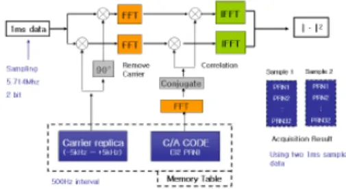
Fig 2 shows the conceptual diagram of signal acquisition module. The acquisition module contains look up table which contains FFT processed carrier and PRN code, and FFT implementation related tools. The FFT results of carrier and C/A code are stored in loop-up table with 1ms unit to save calculation time. The details of the algorithm are followed. First the stored GPS signal are multiplied carrier replica to carrier wipe off and FFT processed C/A code is multiplied with the carrier wipe off data. Then the multiplied data is invert FFT processed, the result just same as convolution of received data and replica data in time domain. The final result is I phase and Q phase square summed to use in detection of GPS signal. If the value is larger than thresh hold then the signal acquisition is done.
Fig. 2 Block diagram of signal acquisition concept.
2.1.1 Signal Doppler Estimation
In many GPS receiver applications it is desirable to minimize the time form receiver turn on until the first navigation solution is obtained.
This time interval is commonly called TTFF(time
to first fix). the TTFF can be further reduced if
the approximate Doppler shifts of the visible
satellite singles are known. This permits the
receiver to establish a frequency search pattern I
which the most likely frequencies of reception of
reception are searched first. The expected Doppler
shifts can be calculated form knowledge of
approximate position, approximate time, and valid almanac data. The greatest benefit is obtained if the receiver has a reasonably accurate clock reference oscillator.
However, once the first satellite signal is found, a fairly good estimate of receiver clock frequency error can be determined by comparing the predicted Doppler shift with measured Doppler shifts. This error can then be subtracted out while searching in frequency for remaining satellites, thus significantly reducing the range of frequencies that need to be searched[5].
2.1.2 GPS signal frequency characteristics, modulation methods and their characteristics
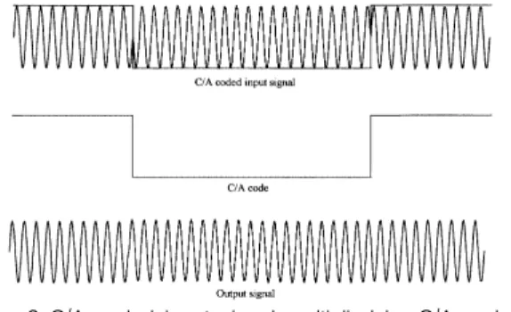
The basic idea of acquisition is to dispread the input signal and finds the carrier frequency. If the C/A code with the correct phase is multiplied on the input signal, the input signal will become a cw signal as shown in Fig.3 [4].
Frequency: The frequency of the signal from a specific satellite can differ from its nominal value.
In the case of down-conversion, the nominal frequency of the GPS signal on L1 corresponds to the IF. However, the signals are affected by the relative motion of the satellite causing a Doppler effect. The Doppler frequency shift can in case of maximum velocity of the satellite combined with a very high user velocity approach values as high as 10 kHz. For a stationary receiver, the Doppler frequency shift will never exceed 5 kHz.
Code Phase: The code phase denotes the point in the current data block where the C/A code begins.
If a data block of 1ms is examined, the data includes an entire C/A code and thus one beginning of a C/A code.
Fig. 3 C/A coded input signal multiplied by C/A code.
Many different methods have been used, but they are all in one way or another based on the GPS signal properties. Especially the C/A code correlation properties are important. The received signal s is a combination of signals from all n visible satellites:
⋯
When acquiring a satellite k, the incoming signal s is multiplied with the local generated C/A code corresponding to the satellite k. The cross-correlation of the pseudo range calculated later on. The tracking contains two parts, code tracking and carrier frequency/phase tracking.
The spectrum shape resembles the shape of the filter in the RF chain. After the circular correlation, the beginning of the C/A code of satellite 6 is shown in Fig.4. The beginning of the C/A code is at 2122. The amplitudes of the 21 frequency components separated by 1 KHz are shown in Fig.5.
From Fig.4 and Fig.5, one can see that the initial
point of the C/A code and the frequency are
clearly shown. Since the data are actually
collected, the accuracy of the fine frequency is
difficult to determine because the Doppler
frequency is unknown. The fine frequency also
depends on the frequency accuracy of the local
oscillator used in the down conversion and the
accuracy of the sampling frequency. One way to
get a feeling of the calculated fine frequency
accuracy is to use different portions of the data.
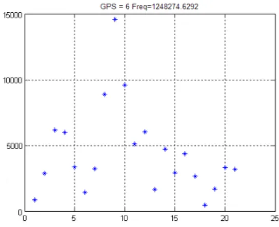
Six fine frequencies are calculated from different portions of the input data. The data used are 1-25000,5001-30001, 10001-35001, 15001-40001, 2001-45001, 2501-50001. These data are five milliseconds long and the starting points are shifted by 1 ms. Between two adjacent data sets four out of the five milliseconds of data are the same. Therefore, the calculated fine frequency should be close. The fine frequency differences between these six sets are −2.4, 9.0, −8.2, 5.4, and 2.3 Hz. These data are collected at a stationary set. The frequency change per millisecond should be very small. Thus ,the frequency difference can be considered as the inaccuracy of the acquisition method. When the signal strength changes, the difference of the fine frequency also changes.
Fig. 4 Beginning of C/A code of satellite 6.
Fig. 5 Frequency component of the dispread signal of satellite
The acquisition performed on a weak signal (satellite 24) is shown in Fig.6 and Fig.7. From these figures, it is difficult to assess whether the beginning point of the C/A code and the frequency are the correct values. The beginning of the C/A code and the fine frequency can be found by adding more calculations incoherently. The correct results are different from the maximum shown in Fig.6 and Fig.7.
Fig. 6 Beginning of C/A code of satellite 24.
Fig. 7 Frequency component of the dispread
signal of satellite 24.
Ⅲ. SIGNAL TRACKING MODULE
The tracking loop follows the incoming signal and adjusts itself to de-spread and de-modulate the incoming signal. If the receiver is stationary, the rate of change of Doppler frequency is small and hence the update rate of tracking loop is also small.
In order to track the incoming GPS signal, we need to use two tracking loops. Delay Lock Loop (DLL) is used to track the C/A code (de-spread) and Phase Lock Loop (PLL) is used to track the frequency of the incoming signal that is related with Doppler frequency. Fig.8 shows the algorithm details of tracking loop. DLL consists of early, prompt and late code generators, filters and discriminators. The early and late codes are prompt code that is time shifted by half a chip or less.
The early an late codes correlate with incoming C/A codes to produce two outputs. These outputs are filtered, squared and compared using a discriminator. Based on discriminator output, a control signal can be generated to adjust the rate of the locally generated C/A code to match the C/A code of the incoming signal. Different discriminators can be used, for example, E-L envelope (which is used in the present algorithm), E-L power or E-L normalized. The locally generated prompt signal is used to de-spread the incoming signal.
Fig. 8 Algorithm details for signal tracking loop.
Ⅳ. CONCLUSIONS
We have completed the algorithms for acquisition. Software-based GPS receivers, which are the focus of current research, because of their easy reprogramming and flexibility. Sampling an incoming wideband signal will allow the receiver to capture more navigation signals from different standards.
We analyze the different methods of acquisition and the use of simulation software for the simulation. The simulation results further confirm the correctness of the method and feasibility of this simulation platform in the real environment for further study of the GPS signal. We can see that, to improve the performance of some of the satellite receiver, this method has a very important practical significance.
References
[1] M. Braasch and Dierendonck, “GPS receiver architectures and measurements,” Proceedings of the IEEE, vol. 87, issue 1, Jan. 1999, pp. 48-64.
[2] Yang, “Sequential Block Search for Direct Acquisition of Long Codes under Large Uncertainty,” ION NTM 2001, Long Beach, CA, Jan. 2001, pp. 22-24.
[3] Ba. James and Tsui, “Fundamentals of Global Positioning System Receivers,”- A Software Approach, John Wiley & Sons, 2005, pp.133-159.
[4] Mohinder S. Grewal, Lawrence R. Weill, Angus P. Andrews, “Global Positioning Systems, Inertial Navigation, and Integration,” A Software Approach, John Wiley & Sons, 2001,pp. 46-47.
[5] Y. Suh, “A Comparision of Raptor Code Using LDGM and LDPC Code,” J. of the Korea Institute of Electronic Communication Sciences, vol. 18, no.
1, 2013, pp.65-70.
[6] S. Chen and H. Suh, “An Effective Decoding
Algorithm of LDPC Codes with Lowering Error Floors,” J. of the Korea Institute of Electronic Communication Sciences, vol. 9, no. 10, 2014, pp.
1111-1116.
[7] H. Chen and H. Suh, “An Improved Bellman-Ford Algorithm based on SPFA,” J. of the Korea Institute of Electronic Communication Sciences, vol. 7, no. 4, 2012, pp. 721-726.
[8] C. Berrou A. Glavieux, and P. Thitimajshima:
”Near Shannon Limit error-correcting coding and decoding: Turbo Codes” ICC’93, Conf. Rec., Geneva, May 1993, pp. 1064-1070.
[9] Hagenauer, J. and Papke, L., i.Decoding turbo codes with the soft-output Viterbi algorithm (SOVA), lm in Proceedings of International Symposium On Information Theory (Trondheim, Norway), June 1994, p. 164.
[10] Yanji and H. Suh, “A Comparision of Raptor Code Using LDGM and LDPC Code,” J. of the Korea Institute of Electronic Communication Sciences, vol. 18, No. 1, 2013, pp.65-70.
[11] S. Chen and H. Suh, “An Effective Decoding Algorithm of LDPC Codes with Lowering Error Floors,” TJ. of the Korea Institute of Electronic Communication Sciences, vol. 9, no. 10, 2014, pp.
1111-1116.
[12] Hao Chen and H. Suh, “An Improved Bellman-Ford Algorithm based on SPFA,” J. of the Korea Institute of Electronic Communication Sciences, vol. 7, no. 4, 2012, pp. 721-726.
저자 소개
장위(Zhang, Wei)
1997년 북경연합대학교 졸업(공학사) 2010년 전남대학교 대학원 전자통 신공학과 졸업(공학석사)
현재 북경석유화공학원 교수
※ 관심분야 : 무선통신시스템, 위성통신
서희종(Hee-Jong Suh)