Kim, Jin-Ho Park, Ok-Jeoung Chun, Min-Chul
---
---
1. INTRODUCTION
Increased demand for higher speed to shorten travel time creates disturbance to human and the environment due to strong vibration. Therefore, vibration reduction has become a topic of special interest in recent years as the speed of train systems is mounting. Experience shows that the vibration induced by the high-speed rail can reach levels that cause human annoyance, possible damage to old and historical buildings, and interruption of sensitive instrumentation and processes. In addition, there are rising concerns over the running safety of the trains, degradation of the embankment and foundation soil, fatigue failure of the rails, and disruption of power supply to the trains. Therefore, the selection of a suitable vibration mitigation strategy becomes a challenging issue for engineers.
Deep mixing technology, as discussed in the following sections, is an innovative technique that is being used to mitigate the detrimental effects of vibration caused by high-speed trains. Accordingly, the objective of this paper is to present the latest advancements in Europe and Japan when deep mixing technology is used as the countermeasure against vibration control. The current state of practice to analyze and predict the response of treated ground based on analytical and numerical solutions are discussed along with a summary of rare field data ---
from Sweden and Japan.
2. DEEP MIXING TECHNOLOGY
The need for straight railway line to support high-speed train may force a route to pass through soft and compressible soils, such as organic soils, peat, and soft marine clays. Actual observations and measurements with high-speed trains have revealed that one might observe remarkably large vibrations in soft soil sites from the moving-load excitation mechanism. Sites with low shear-wave velocities, in the range of 30 to 40 m/s, are particularly susceptible to excessive vibration from high-speed trains.
Many factors influence the ground vibration amplitude and spectrum induced by high-speed train. Basically, ground vibrations by railway traffic are generated by two prime excitation mechanisms (a) the quasi-static displacement caused by the axle load as the wheel moves along the track, and (b) the inertia forces due to the acceleration of the unspring mass of the train as it rolls over the irregular profile of the railhead . As the speed of the load increases, dynamic phenomena gradually take over and dominate the response. Figure 1 illustrates recordings at 7.5m, 15m, and 22.5m from the track for a train with a train speed of 200 km/h in Sweden [1].
Figure 1. Measured track-side vibration for train speed 200 km/h [1]
Deep mixing is a ground modification technology that mixes in situ soil with a cementitious material (such as cement, lime, etc) using specially designed equipment with paddles and/or augers [2]. The advantages of deep mixing are: (a) accelerated construction process (in terms of reducing construction time); (b) wide range of finished products (in terms of controllable strength, stiffness, etc) (c) environmentally friendliness (in terms of noise and vibration for construction in the urban areas), and (d) wide spectrum of applications in the construction industry. The scope of the application of deep mixing is to handle and solve problems associated with:
Increasing bearing capacity Reduction of settlement Prevention of sliding failure Excavation support
Hydraulic barrier (controlling seepage and cutoff systems for containment)
Seismic/liquefaction mitigation (reducing shear deformation) Remediation/immobilization/confinement of contaminated ground Increasing drivability for tunneling in soft ground; and
Vibration impediment
Current methods for analysis of ground treated by deep mixing technology to impede vibration are discussed below.
3. ANALYTICAL AND NUMERICAL APPROACH
Moving loads, such as high-speed trains, have long been recognized as potential source of ground vibration.
The ground response to a moving load is dictated largely by the relation between the load speed and the characteristic wave velocities of the ground medium [3]. Analytical and numerical methods have been proposed to predict the effect of ground response and vibration impediments when deep mixing is used as the countermeasure.
The analytical method that is used in this study is based on the principles of wave propagation theory. The vibration generated by a vibrating source is generally damped with distance. Distance damping is influenced mainly by ground condition and the wave properties at the surface, as follows:
{
( )}
exp 0
0 x x
x x u u
o
x = ⋅ −β −
(1)
Where ux: vibrational acceleration at x(m) from vibration source; u0: vibrational acceleration at x0 (m) from vibration source and near the source; and β: damping coefficient. When deep mixing is used, the impedance effect of wave in the treated ground is taken into consideration. Generally, when a material with different stiffness/density exists inside the ground, the propagated wave from a source behaves such that a portion of the waves reflects due to impedance difference. And the rest is transmitted but reflects as it propagates outside the barrier that obstructs the vibration. The reduction ratio of wave (ratio between transmitting wave and incoming wave) is estimated using the wave propagation theory, as follows:
2 / 1 2
2 4
4
0=4α/{(1+α) +(1−α) −2(1−α ) ×cos(4πft/V′)}
τ (2)
Where: α=ρ′V′/ρV: ρ(Mg/m3): density of ground; '(Mg/m3): density of blocking layer; V(m/sec): wave propagation speed of ground; V'(m/sec): wave propagation speed of blocking layer; t(m): blocking layer thickness; and f (Hz): frequency of the wave.
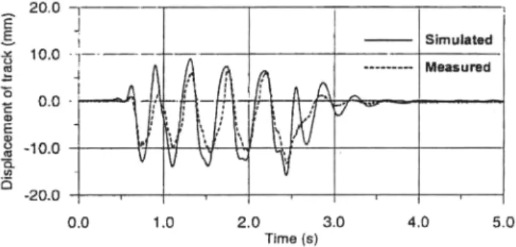
A rigorous numerical model for the simulation of ground vibration from high-speed trains was developed. The ground was modeled as a layered visco-elastic half space, and the track embankment was modeled as a layered visco-elastic beam that interacts with the ground at discrete points. The model used the Kausel-Roesset Green's function to obtain the soil stiffness matrix at the ground-embankment interface nodes and assembled with the dynamic stiffness matrix of the embankment. The solution was carried out in the frequency domain and the time histories of the motions were calculated through a Fourier synthesis of frequency components. Figure 2 shows typical results obtained for this study. The numerical solution was used to demonstrate the effectiveness of strengthening the embankment for mitigating ground vibration.
Figure 2. Measured and simulated time history of vertical track motion at a speed of V = 200 km/h
4. FIELD TESTS
Field tests have been performed both in Europe and in Japan to measure ground vibration and predict the effect of countermeasures by high-speed trains. Here two case examples are presented.
4.1 Case Study in Europe
(a) Before ground stabilization (b) After ground stabilization Figure 3. Particle velocity at 7.5m from the track during passage of freight train [4]
An extensive measurement program was undertaken at a site along the West Goteborg and Malmo in Sweden [1]. The soil at the site consists of about 1.5m weathered dry crust overlaying about a 3m thick layer of soft clay with organic content, and below that is soft marine clay with gradually increasing shear strength with depth. The bedrock is at about 70m. A total of 20 test runs were made with train speeds ranging from 10 to 200 km/h. The motions of the track and embankment at several depths as well as the response of the nearby ground were recorded by a host of sensors including accelerometers, seismometers, and electronic displacement transducers.
Receivers were installed in rectangular patterns at horizontal space of 7.5 m and at a depth of 3 to 5 m.
Deep mixing using lime as the binder was used to stabilize the base of the tracks. It is reported the results of particle velocity measurement at the site before and after the soil stabilization for two similar freight trains, as presented in Figure 3. The amplitude of particle velocity before base stabilization was between -5 to +5 mm/sec.
After installation of deep mixed columns the variation in velocity was in the range of 3 to +3 mm/sec. The higher amplitudes were measured after 7 seconds before ground stabilization were increased to 16 second when deep mixing columns were installed.
4.2 Case Study in Japan
(a) (b)
Figure 4. Variation of acceleration with speed and distance from the vibrating source [5]
The test site was in the Ariake Sea side of Rokkaku River, which is located in Southwest part of the Saga Plan in Western Japan [5]. Before the test undistracted samples from the site were collected with thin wall sampling method. Soil profile consists of 0.7m surface fill underlain by Ariake clay layer down to 13.5m resting on 1.5m sand layer. The unconfined compressive strength of clay starts from 20kPa at the top and increases with depth to reach 40kPa at the bottom of the clay layer. The moisture content was 100% to 120%. The treated ground consists of deep mixed continuous walls of 15m long, 7m deep, made of columns of 1.14m diameters with 20cm of outer overlapped edge. The binder is a cement-based solidification agent consisting of blast furnace cement and hydrated lime. The purpose of the experiment was not for high-speed train, but to understand the vibration impedance caused by heavy construction machinery on deep mixed treated ground.
Figure 4a illustrates the relationship between running speed and generated acceleration. From this figure, the survey at point 3 with deep mixed columns has the lowest recorded acceleration. Figure 4b shows the damping of vibrational acceleration with respect to distance. More specifically, at the location in which deep mixed columns are installed, (survey point 3) the generated acceleration is readily small. This is attributed to the stiffness of the treated ground that dampens vibrational acceleration. Using the analytical solution discussed earlier the reduction ratio of treated columns determined by substituting the respective material properties (ρ = 1.40, ρ' = 1.50, V = 40.0, V' = 850, t = 2.0, f = 6.0) was estimated to be 0.705.
5. CONCLUSIONS
This study presents the current understanding and state-of-practice in using deep mixing technology for vibration impediment. The limited and rare field data from Japan and Sweden is presented to portray the current level of understanding. Measurements performed before and after installation of deep mixed columns under railway embankment at the site in southern Sweden demonstrated that train induced vibrations can be reduced effectively by this method. The complexity of train-induced vibration and high cost of field tests dictates taking advantage of advanced numerical techniques to predict the effect of countermeasures. The numerical solutions have demonstrated effective tools to predict improvement effect of deep mixing as a countermeasure for vibration control. The references provided at the end of this article are aimed to serve as a source for deep mixing technology and vibration impediment issues.
REFERENCES
Survey point 1
Survey point 4 Survey point 3
Acceleration
Running speed (km/h)
Survey point 2
Survey pt. No.
Running speed
Running center position Improvement column position
Acceleration
Distance from running center (m)
1. SGI Report (1999) "High Speed Lines on Soft Ground: Evaluation and Analyses of Measurements from the West Coast Line", Report No. Dnr. 2-9710-502, Swedish Geotechnical Institute, Stockholm, Sweden
2.A. Porbaha, J-L. Raybaut, and P. Nicholson (2001), "State of the Art in Construction Aspects of Deep Mixing Technology", Ground Improvement, Journal of International Society of Soil Mechanics and Geotechnical Engineering, Vol. 5, No. 3, pp. 123-140
3. A. Kaynia, C. Madshus, and P. Zackrisson (2000), "Ground Vibration from High-Speed Trains: Prediction and Countermeasure", Journal of Geotechnical and Geoenvironmental Engineering, ASCE, Vol. 126, No. 6, pp. 531-537
4. M. Bahrekazemi, and A. Bodare (2001) "Soil stabilization by Lime-Cement Columns as a Countermeasure against Train-Induced Ground Vibrations", Proc. of the 15th International Conference on Soil Mechanics and Geotechnical Engineering, pp. 1695-1700
5. K. Koga,, N. Miura,, R. Nakamura, and K. Nishida (1998) "The Field-Test of Isolation of Ground Vibration by Use of Columnar-Inclusions", Tsuchi-To-Kiso, JGS Ser. No. 490, Vol. 46, No. 11, Report-2551
![Figure 1. Measured track-side vibration for train speed 200 km/h [1]](https://thumb-ap.123doks.com/thumbv2/123dokinfo/5394268.415716/2.892.297.640.493.823/figure-measured-track-vibration-train-speed-km-h.webp)
![Figure 4. Variation of acceleration with speed and distance from the vibrating source [5]](https://thumb-ap.123doks.com/thumbv2/123dokinfo/5394268.415716/5.892.182.727.149.381/figure-variation-acceleration-speed-distance-vibrating-source.webp)
