DOI: http://dx.doi.org/10.7316/KHNES.2014.25.2.105 eISSN 2288-7407
Ni/Ce-ZrO
2/Al
2O
3촉매의 첨가제에 따른 수소 및 합성가스 생성에 대한 실험적 연구
조원준1†ㆍ유혜진1,2ㆍ모용기1ㆍ안화승2
1한국가스공사 연구개발원(KOGAS) DME기술연구센터, 2인하대학교 화학공학과
Experimental Study of Hydrogen and Syngas Production over Ni/Ce-ZrO
2/Al
2O
3Catalysts with Additives
WONJUN CHO1†, HYEJIN YU1,2, YONGGI MO1, WHASEUNG AHN2
1DME Technology Research Center, KOGAS, 960 Incheonshinhang-daero, Yeonsu-gu, Incheon, 406-840, Korea
2Department of Chemistry and Chemical Engineering, Inha University, Yonghyun-dong, Nam-gu, Incheon 402-751, Korea
Abstract >> Performance tests on Ni/Ce-ZrO2/Al2O3 catalysts with additives (MgO, La2O3) were investigated in the combined reforming processes (SCR, ATR, TRM) in order to produce hydrogen and carbon monoxide (it is called “syngas”.). The catalyst characterization was conducted using the BET surface analyzer, X-ray diffraction (XRD), SEM, TPR and TGA. The combined reforming process was developed to adjust the syngas ratio depending on the synthetic fuel (methanol, DME and GTL) manufacturing processes. Ni-based catalysts supported on alumina has been generally recommended as a combined reforming reaction catalyst. It was found that both free NiO and complexed NiO species were responsible for the catalytic activity in the combined reforming of methane conversion, and the Ce-ZrO2 binary support employed had improved the oxygen storage capacity and thermal stability. The additives, MgO and La2O3, also seemed to play an important role to prevent the formation of the carbon deposition over the catalysts. The experimental results were compared with the equilibrium data using a commercial simulation tool (PRO/II).
Key words : Combined reforming of methane(복합개질반응), SCR(Steam-CO2 reforming, 수증기-이산화탄소 개 질반응), ATR(Autothermal reforming, 자열개질반응), TRM(Tri-reforming, 삼중개질반응), Syngas (합성가스), Ni/Ce-ZrO2/Al2O3 catalyst(촉매)
†Corresponding author : [email protected]
[ 접수일 : 2014.3.7 수정일 : 2014.4.1 게재확정일 : 2014.4.30 ] Copyright ⓒ 2014 KHNES
1. Introduction
In general, “synthetic fuel” refers to fuels manufactured via Fischer-Tropsch conversion, methanol to gasoline
conversion or direct liquefaction. Conversion technologies in the commercial processes could be either direct conversion to liquid fuels or indirect conversion of the source substance initially to “syngas” which then goes through additional conversion process to make a liquid fuel. The growing attention to the production of syngas (H2/CO) is attributed to the convert of synthetic
fuel from natural gas, biomass, coal and/or coal base gas.
Synthesis gas or “syngas” is a mixture of hydrogen and carbon monoxide used as a major intermediary for the production of pure hydrogen or other chemical compounds. Syngas is manufactured industrially from hydrocarbon fuels either by steam reforming (SRM), catalytic partial oxidation (CPO), carbon dioxide reforming (CDR), autothermal reforming (ATR) or tri-reforming (TRM)[1-5].
Steam reforming of hydrocarbons, in particular methane, is probably the most common and economical method for producing syngas in industrial scale. In this process, methane reacts with steam in the presence of a hetero- geneous catalyst to produce hydrogen, carbon dioxide, and carbon monoxide. Though this process can yield high concentration of hydrogen (up to 70% on a dry basis), it is strongly endothermic. Hence, the reformer needs external heat to be supplied through the reactor wall to perform the fuel reforming, and consists of high capacity gas fired furnaces with a large number of parallel reactor tubes inside. The overall configuration of steam reformer with heat exchangers makes the reforming system very bulky and heavy.
To overcome the heat transfer problem in a steam reformer, the CPO has been often used as an alternative to produce hydrogen or synthesis gas from methane.
The process is exothermic and can be easily started up upon ignition even without an aid of a catalyst.
The temperature can be raised to over 1,000°C in the process which permits adiabatic operation and promotes SRM of the remaining species. However, CPO produces high carbon monoxide concentration. ATR combines the thermal effects of the SRM and CPO reactions by feeding the fuel, water, and air together into the reactor.
The two processes occur simultaneously in the presence of catalyst in the reactor. The thermal energy generated from CPO is absorbed by SRM and, hence, the overall temperature is lowered, which is favorable to water-gas shift reaction to consume carbon monoxide and produce more hydrogen. Hence, the autothermal reformer is more compact and practical.
In recent years, the catalytic process of carbon dioxide reforming of methane into synthesis gas has attracted attention from many researchers for chemical utilization of the undesirable greenhouse gases: natural gas and carbon dioxide. This process produces synthesis gas with a H2/CO ratio of about 1, which can be preferentially used for production of liquid hydrocarbons and oxygenates. Nevertheless, widespread implementation of this approach faces significant hurdles such as the problem of serious coking on the catalysts via the Boudouard reaction (2CO → C + CO2) and/or methane decomposition (CH4 → C + 2H2).
TRM is a synergetic combination of CDR, SRM, and CPO of methane in a single reactor. The tri-forming concepts represents a new way of thinking both for conversion and utilization of CO2 in flue gases without CO2 separation and for production of industrially useful synthesis gas with desired H2/CO ratios using flue gas or natural gas.
KOGAS has also developed and established a new innovative TRM technology since 2001[6]. The combination of dry reforming with steam reforming can accomplish two important missions: to produce syngas with desired H2/CO ratios and to mitigate the carbon formation problem that is significant for dry reforming. Integrating steam reforming and partial oxidation with CO2 reforming could dramatically reduce or eliminate carbon formation on reforming catalyst thus increase catalyst life and
process efficiency.
The typical catalyst for combined reforming process (SCR, ATR and TRM) is composed of the supported Ni catalyst with additives. It is important to develop and select the suitable Ni base catalyst because of sintering of Ni particle and carbon formation on the catalyst during the operation for producing the syngas in the combined reforming.
The objectives of this work is to investigate the catalytic performance of the Ni/Ce-ZrO2/Al2O3 catalyst with the additives (MgO, La2O3) developed by us for the KOGAS combined reforming process.
2. Experimental
2.1 Preparation of catalysts
The catalysts were prepared by the following method.
The loading amount of Ni was fixed to 9wt%. Ce-ZrO2/ Al2O3 support was prepared by the co-impregnation method. Cerium (III) acetate hydrate and zirconium nitrate were dissolved in distilled water with stirring 500rpm. This mixed solution was impregnated on α- Al2O3. This material was calcined at 900°C for 6hr in air. The supported Ni catalyst was prepared by the impregnation using a solution of nickel (III) nitrate hexahydrate onto Ce-ZrO2/Al2O3 support, followed by drying in microwave oven and calcining at 750°C for 6hrs in air[7]. La2O3-promoted catalyst was prepared by the co-impregnation method using a aqueous soloution of nickel (III) nitrate hexahydrate and lanthanum nitrate hexahydrate on Ce-ZrO2/Al2O3. MgO-promoted catalyst was also prepared by the same method. The prepared catalysts were denoted as Ni/Ce-ZrO2/Al2O3, Ni-La2O3/ Ce-ZrO2/Al2O3 and Ni-MgO/Ce-ZrO2/Al2O3
respectively.
2.2 Characterization
The BET surface area, total pore volume and average pore diameter of the catalysts were measured by nitrogen adsorption at -196°C using a BET instrument (Micromeritics, ASAP2020). About 0.05g of catalysts was used. The samples were pre-treated in high vacuum at 150°C to remove moisture and other adsorbed gases from the catalyst surface. X-ray diffraction (XRD, Bruker, D2Phase) patterns were recorded to investigate the crystal structure and compositional homogeneity of the prepared catalysts. The crystallite size was estimated by using the Scherrer equation. Temperature programmed reduction (TPR) experiments were carried out in an Autochem 2920 (Micromeritics). The sample of 50mg in a quartz reactor was pre-treated with He gas at 250°C for 1hr under He flow (50ml/min), cooled down to 50°C and then reduced using 10%vol H2/Ar with a heating rate of 10°C/min from 50 to 1,000°C.
A thermal conductivity detector was used to analyse the effluent gas after water trapping, and quantification of hydrogen consumption was carried out[8].
The morphologies of fresh catalysts were examined by scanning electron microscopy (SEM, Hitachi, S-4200).
The quantitative analysis of coke amount on the used catalyst was performed with a thermogravimetry analyzer (TGA, NETZSCH, STA 409 PC). The sample of 20-40mg was heated from 30 to 1,400°C with a heating rate of 10°C/min in air.
2.3 Catalytic reaction
The methane reforming performance of the catalysts were investigated using a high pressure fixed-bed reactor system. The reactor with an inner diameter of 8mm was heated in an electric furnace a shown Fig. 1.
① MFC
② Water Feed pump
③ Gas mixer & heater
④ Boiler
⑤ Pre-reformer
⑥ Pre-heater
⑦ SCR reactor
⑧ Heat exchanger
⑨ Temp' controller
⑩ GC
⑪ PC
Fig. 1 The schematic diagram of reactor set-up
Table 1 Characteristic of the catalysts
Catalyst
surface area (m2/g)a
Ni crystallite size (nm)b
Pore volume
(cc/g)
Average pore diameter
(nm) Ni/Ce-ZrO2/Al2O3 5.2 25.8 0.03 21.0 Ni-La2O3/Ce-ZrO2/Al2O3 4.9 41.0 0.02 18.9 Ni-MgO/Ce-ZrO2/Al2O3 5.9 30.3 0.06 23.2
aEstimated from N2 adsorption at -196°C.
bEstimated from XRD
SCR, ATR and TRM reforming reactions were carried out at 900°C, 20 bar. For each run, 7.0g catalyst was loaded into a reactor[9]. The ratio of CH4/H2O/CO2 in the feed gas was kept to 1.0/1.6/0.9 in order to produce a proper ratio of H2/CO to make reactants for Fischer-Tropsch reaction (F-T reaction), and the space velocity was about 4,000hr-1 in SCR.
In the ATR process, the ratio of CH4/H2O/O2 was maintained as 1.0/1.0/0.8, and CH4/H2O/CO2/O2 was kept to 1.0/0.8/1.1/0.8 in the TRM process to make the suitable ratio of syngas. In the reactions, CH4
feed flow rate was fixed to 150ml/min. The effluents from the reactor were analyzed on-line with a gas chromatograph (GC, Younglin, Autochro 2000) using a packed column (Porapak N) equipped with a thermal conductivity detector (TCD) and flame ionization detector (FID).
The conversion of CH4 and CO2, the yield of H2, CO, and H2/CO ratio was calculated on the basis of the feed flow rates and the dry exit gas composition as obtained by gas chromatography using the following formulas[10].
×
×
×
×
×
×
3. Results and Discussion
3.1 Catalyst characterization
Table 1 summarizes the characteristics of the catalysts prepared by the co-impregnation method. It shows the BET surface area, pore volume, and the size of Ni particles in the Ni/Ce-ZrO2/Al2O3 and those with additives (La2O3 and MgO) catalysts.
The surface areas of the prepared catalysts were all in the range of 4.9-5.9m2/g. Ni crystallites of the catalysts were also close but Ni-La2O3/Ce-ZrO2/Al2O3
showed somewhat larger size than the others.
Fig. 2 XRD data of the catalysts prepared
(a) Ni/Ce-ZrO2/Al2O3 (b) Ni-La2O3/Ce-ZrO2/Al2O3 (c) Ni-MgO/Ce-ZrO2/Al2O3
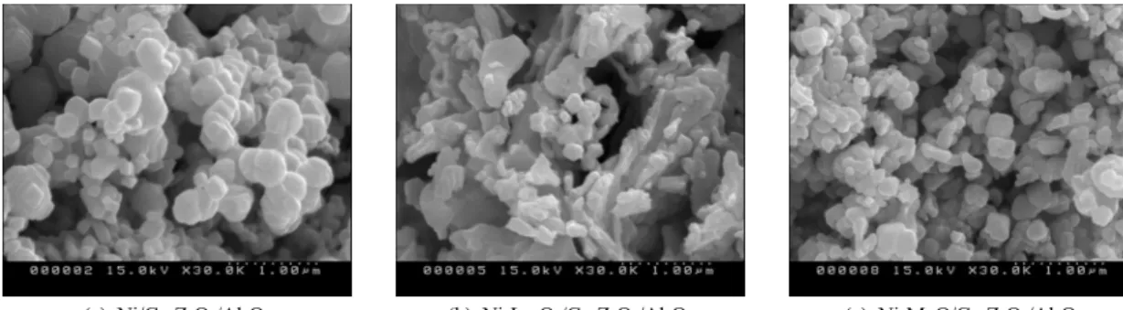
Fig. 4 SEM images of various catalysts
Fig. 3 TPR patterns of various catalysts
The XRD patterns of the Ni/Ce-ZrO2/Al2O3, Ni-La2O3/Ce-ZrO2/Al2O3 and Ni-MgO/Ce-ZrO2/Al2O3, are given in Fig. 2. The main phase of nickel in these catalysts was NiO that exhibited three major peaks at 2 theta values of 37.1°, 43.2° and 62.7°[11]. For the La2O3-promoted catalyst, the characteristic reflections of lanthanum were present at 35.0°, 45.1°, 55.4°. For the Ni-MgO/Ce-ZrO2/Al2O3 catalyst, MgO phase was detected to co-exists with NiO. It was difficult to distinguish clearly the MgO peak from the NiO peak because the peaks overlap each other[12].
The TPR patterns obtained for the catalysts prepared by co-impregnation method are shown Fig. 3. The temperature for free NiO reduction was 303°C[13] or
higher, depending on the additives. It is known that the peaks at lower temperatures are assignable to reduction of relatively free NiO species, whereas the peaks at higher temperatures are attributed to the reduction of complexed NiO species subjected to strong metal to support interaction (SMSI)[14].
In the case of Ni-La2O3/Ce-ZrO2/Al2O3 catalyst, the peak detected at 426°C was attributed to reduction of species of lanthanum. In the case of Ni-MgO/
Ce-ZrO2/Al2O3 catalyst, the reduction peak at around 938°C peak could be assigned to reduction of complexed NiOx species[15].
The morphologies of the fresh catalysts were monitored by SEM analysis, as shown in Fig. 4. The fresh
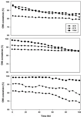
Fig. 5 Catalytic performance test ((a) : SCR, (b) : ATR, (C)
: TRM) Fig. 6 Long term test according to Ni/Ce-ZrO2/Al2O3 with the additives ((a) : Ni/Ce-ZrO2/Al2O3 (b) : Ni-La2O3/ Ce-ZrO2/Al2O3 (c) : Ni-MgO/Ce-ZrO2/Al2O3)
Ni/Ce-ZrO2/Al2O3 catalyst showed relatively uniform spherical particles with little agglomeration, whereas the fresh Ni-La2O3/Ce-ZrO2/Al2O3 catalyst showed particles with a wide distribution of different particle sizes and shapes. Ni-MgO/Ce-ZrO2/Al2O3 catalyst showed better dispersion of spherical particles than the La2O3- added catalyst[16].
3.2 Catalytic performance test
The prepared catalysts were tested for their catalytic activities in SCR, ATR and TRM at 900°C and 20bar condition. Fig. 5 shows CH4 and CO2 conversion and selectivities to H2 and CO in respective processes.
High CH4 conversion and adequate syngas ratio were obtained over the Ni-La2O3/Ce-ZrO2/Al2O3 catalyst,
which showed the best performance among the catalysts tested in the SCR process. In the ATR Process, CH4
conversion was 96.5% over Ni/Ce-ZrO2/Al2O3 catalyst with the syngas ratio (H2/CO) of ca. 2.0 suitable for F-T synthesis.
For DME production with TRM process, the syngas ratio was required to be 1.2±0.2. In the reaction test, Ni-MgO/Ce-ZrO2/Al2O3 catalyst satisfied the required synthesis gas ratio and achieved the highest CH4
conversion of 98.6%. Therefore, it is indicated that MgO as additive to the Ni/Ce-ZrO2/ Al2O3 is adequate for TRM process.
To evaluate the long term performance of the catalysts, the effectiveness of the catalysts was tested for 100 hr. As shown in Fig. 6, deactivation of catalysts Ni/Ce-ZrO2/Al2O3 and Ni-La2O3/Ce-ZrO2/Al2O3 occurred
Fig. 7 TGA profiles of the used catalysts
Fig. 8 Flow diagram for reactor modeling by Pro/II simulation program
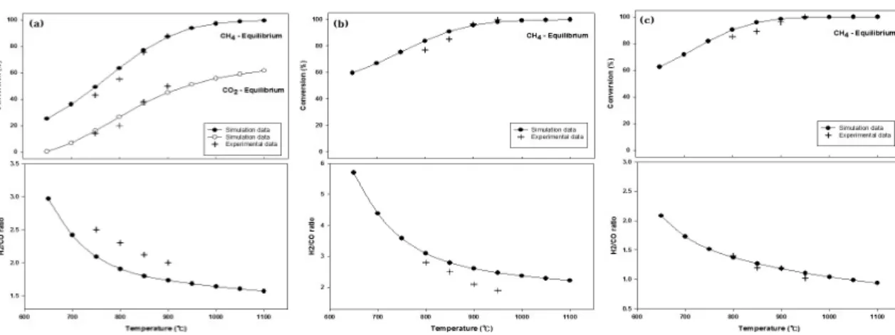
Fig. 9 Comparison of the simulation and experimental results((a) : SCR (b) : ATR (c) : TRM)
in ATR and TRM processes that involve O2 as a feedstock.
Ni/Ce-ZrO2/Al2O3 catalyst showed higher activity and was stable for ATR process. Despite lower catalytic
activity, Ni-La2O3/Ce-ZrO2/Al2O3 was also relatively stable for 100hr. It is confirmed that Ni/Ce-ZrO2/Al2O3
with added MgO shows the highest CH4 conversion and stable activity in the long-term test. It is well established that selection of additives is important for enhancement in catalytic activity and stability in the mixed reforming process. The additives were effected to interact between NiOx species and support[17].
The carbon deposition on the used catalysts were monitored by TGA. Fig. 7 shows that all catalysts exhibited decreases in weight to around 400°C. This weight loss is a result of thermal desorption of water and CO2 and to removal of easily oxidizable carbonaceous species[18]. Ni-La2O3/Ce-ZrO2/Al2O3 catalyst, on the other hand, exhibited a weight gain from 400°C to 500°C which is attributed to the nickel oxidation[19].It was shown that the TGA profiles for all three catalysts
showed low weight losses afterwards due to graphitic carbon oxidized at high temperature[20].
Fig. 8 describes a process flow diagram for the reaction process of methane in this work simulated by the PRO/II simulation program to compare the experimental results with the equilibrium values. The simulated reaction processes assume a Gibbs reactor which models a chemical reactor by solving the heat and material balances based on minimizing the Gibbs free energy of the components in the reaction. Fig. 9 showed the comparison of the simulation with experimental results for conversion and H2/CO ratio at 650-1000°C to cover the temperature ranges in SCR, ATR and TRM processes. It found that the conversion and H2/CO ratio over these catalysts showed similar trends with the simulated values.[21]
4. Conclusion
The effect on additives of Ni/Ce-ZrO2/Al2O3 catalyst for the improvement of the catalytic activity and carbon tolerance in SCR, ATR and TRM processes of methane was investigated. The catalysts were prepared by co- impregnation using MgO and La2O3 as additives. In the SCR, high CH4 conversion and acceptable synthesis gas ratio was achieved by Ni-La2O3/Ce-ZrO2/Al2O3
catalyst, whereas Ni/Ce-ZrO2/Al2O3 catalyst performed best for ATR process. In TRM process, MgO was more effective additive to activity and stability.
Acknowledgment
This study was supported by “Korea Gas Corporation R&D program” and “Ministry of Trade, Industry and Energy”.
References
1. H. Arakawa, M. Aresta, and J. N. Armor, “Catalysis Research of Relevance to Carbon Management:
Progress, Challenges, and Opportunities”, Chem.
Rev., Vol. 101, 2001, pp. 953-996.
2. A. M. De Groote, and G. F. Froment, “Simulation of the catalytic partial oxidation of methane to synthesis gas”, Applied Catalysis A: General, Vol.
138, 1996, pp. 245-264.
3. D. L. Hoang, and S. H. Chan, “Modeling of a catalytic autothermal methane reformer for fuel cell applications”, Applied Catalysis A: General, Vol. 268, 2004, pp. 207-216.
4. W. J. Cho, T. Y. Song, A. Mitsos, J. T. Mckinnon, G. H. Ko, J. E. Tolsma, D. Denholm, and T. S.
Park, “Optimal design and operation of a natural gas tri-reforming reactor for DME synthesis”, Catalysis Today, Vol. 139, 2009, pp. 261-267.
5. C. S. Song, “Global challenges and strategies for control, conversion and utilization of CO2 for sustainable development involving energy, catalysis, adsorption and chemical processing”, Catalysis Today, Vol. 115, 2006, pp. 2-32.
6. J. T. Chung, W. J. Cho, Y. S. Baek, and C. H. Lee,
“Optimization of KOGAS DME process from demonstration Long-term test”, Trans. of the Korean Hydrogen and New Energy Society, Vol. 23, 2012, pp. 559-571.
7. H. S. Roh, H. S. Potdar, and K. W. Jun, “Carbon dioxide reforming of methane over co- precipitated Ni-CeO2, Ni-ZrO2 and Ni-Ce-ZrO2 catalysts”, Catalysis Today, Vol. 93-95, 2004, pp. 39-44.
8. K. Y. Koo, H. S. Roh, Y. T. Seo, D. J. Seo, W.
L. Yoon, and S. B. Park, “A highly effective and table nano-sized Ni/MgO-Al2O3 catalyst for gas to liquid (GTL) process”, International Journal of Hydrogen Energy, Vol. 33, 2008, pp. 2036-2043.
9. H. S. Roh, K. W. Jun, and S. E. Park, “Methane- reforming reactions over Ni/Ce-ZrO2/θ-Al2O3 catalysts”, Applied Catalysis A: General, Vol. 251, 2003,
pp. 275-283.
10. S. H. Lee, W. I. Cho, W. S. Ju, B. H. Cho, Y.
C. Lee, and Y. S. Baek, “Tri-reforming of CH4
using CO2 for production of synthesis gas to dimethyl ether”, Catalysis Today, Vol. 87, 2003, pp. 133-137
11. S. Wang, and G. Q. M. Lu, “CO2 reforming of methane on Ni catalysts : Effects of the support phase and preparation technique”, Applied Catalysis B: Environmental, Vol. 16, 1998, pp. 269-277.
12. K. Y. Koo, H. S. Roh, Y. T. Seo, D. J. Seo, W.
L. Yoon, and S. B. Park, “Coke study on MgO- promoted Ni/Al2O3 catalyst in combined H2O and CO2 reforming of methane for gas to liquid (GTL) process”, Applied Catalysis A : General, Vol. 340, 2008, pp. 183-190.
13. S. D. Robertson, B. D. McNicol, J. H. de Baas, S. C. Kloet, and J. W. Jenkins, “Determination of reducibility and identification of alloying in copper-nickel-on-silica catalysts by temperature- programmed reduction”, Journal of Catalysis, Vol.
37, 1975, pp. 424-431.
14. H. S. Roh, K. Y. Koo, and W. L. Yoon, “Combined reforming of methane over co-precipitated Ni-CeO2, Ni-ZrO2 and Ni-Ce0.8Zr0.2O2 catalysts to produce synthesis gas for gas to liquid (GTL) process”, Catalysis Today, Vol. 146, 2009, pp. 71-75.
15. R. Martínez, E. Romero, C. Guimon, and R. bilbao,
“CO2 reforming of methane over coprecipitated
Ni-Al catalysts modified with lanthanum”, Applied Catalysis A: General, Vol. 274, 2004, pp. 139-149.
16. H. S. Roh, H. S. Potdar, K. W. Jun, J. W. Kim, and Y. S. Oh, “Carbon dioxde reforming of methane over Ni incorporated into Ce-ZrO2 catalysts”, Applied Catalysis A: General, Vol. 276, 2004, pp. 231-239.
17. A. I. Tsyganok, T. Tsunoda, S. Hamakawa, K. Suzuki, K. Takehira, and T. Hayakawa, “Dry reforming of methane over catalysts derived from nickel- containing Mg-Al layered double hydroxides”, Journal of Catalysis, Vol. 213, 2003, pp. 191-203.
18. M. Dan, M. D. Lazar, V. Rednic, and V. Almasan
“Methane steam reforming over Ni/Al2O3 promoted by CeO2 and La2O3”, Chem. Rev., Vol. 56, 2011, pp. 643-649.
19. W. Tao, H. Cheng, W. Yao, X. Lu, Q. Zhu, G.
Li, and Z. Zhou, “Syngas production by CO2
reforming of coke oven gas over Ni/La2O3-ZrO2
catalysts”, International Journal of Hydrogen Energy, 2014, http://dx.doi.org/10.1016/j.ijhydene. 2014.
02.029.
20. D. L. Trimm, “Catalysts for the control of coking during steam reforming”, Catalysis Today, Vol.
49, 1999, pp. 3-10.
21. Y. J. Lee, S. I. Hong, and D. J. Moon, “Studies on the steam and CO2 reforming of methane for GTL-FPSO applications”, Catalysis Today, Vol.
174, 2011, pp. 31-36.