Using Carboxylmethylated Cellulose as Water-Borne Binder to Enhance the Electrochemical Properties of Li 4 Ti 5 O 12 -Based Anodes
Lili Liu, Chongling Cheng
a, Hongjiang Liu *, Liyi Shi**, and Dayang Wang
aDepartment of Chemistry, College of Science, Shanghai University, Shanghai 200444, P.R. China
a
School of Civil, Environmental, and Chemical Engineering, RMIT University, VIC 3001, Australia (Received October 12, 2015; Revised October 20, 2015; Accepted October 20, 2015)
···
Abstract The present work reports a systematic study of using carboxymethylated cellulose (CMC) as water-borne binder to produce Li
4Ti
5O
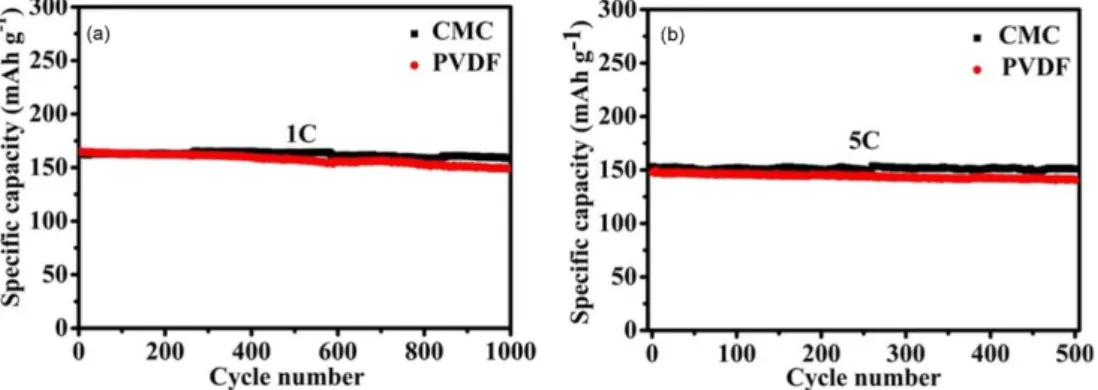
12-based anodes for manufacture of high rate performance lithium ion batteries. When the LTO-to-CB-to-CMC mass ratio is carefully optimized to be 8:1:0.57, the special capacity of the resulting electrodes is 144 mAh·g
−1at 10 C and their capacity retention was 97.7% after 1000 cycles at 1 C and 98.5% after 500 cycles at 5 C, respectively. This rate performance is comparable or even better than that of the electrolytes produced using con- ventional, organic, polyvinylidene fluoride binder.
Keywords: Lithium titanate, CMC binder, Electrochemical properties, Long cycle life
···
1. Introduction
Exhaust gas emitted from vehicles is one of the big- gest contributions to the increasingly serious environmen- tal pollution nowadays. Over the years, a considerable number of efforts have been put in development of envi- ronmental-friendly, green fuels for automobiles instead of fossil fuels [1-3]. In this context, electric vehicles (EVs) and energy storage station (ESS) have been recently developed on the basis of use of high performance lith- ium ion batteries (LIBs) with long cycle life and high energy density [4-9]. However, the stability and safety of LIBs remain the big technical concerns, which limits the commercialization of LIB [10,11]. To address these issues, novel electrode materials with larger lithium ion storage at high rate have been developed [12].
Among currently developed anode materials, spinel Li
4Ti
5O
12(LTO) has attracted increasing attention for its outstanding characteristics. Comparing to commercial graphite anodes, spinel LTO exhibits a very flat and rela- tively higher charge discharge platform at around 1.5 V (versus Li) [13,14]. Thus, it can avoid formation of solid electrolyte interface (SEI) film; otherwise, the latter
results in low coulombic efficiency especially in the first formation cycle due to a significant loss of lithium ion [15]. Spinel LTO has negligible volume change during the lithium intercalation/extraction processes(considered as zero-strain material), which results in excellent cycle stability [16,17].
Typically, LTO electrodes are consisted of active mate- rials (e.g. LTO particles), conductive agents, current col- lectors and binders. The active materials determine the capacity of the electrode. The conductive agents such as carbon black (CB) are used to improve the rate perfor- mance of the electrode owing to the enhanced electric conductivity. The binders are used to glue the active materials and conductive agents together with the cur- rent collectors. Thus, the electrons can flow from/to the outside circuit through the active material–conductive agent–current collector chain. Although the mass frac- tion of the binders are only in the range of 2-10% in a commercial electrode configuration, the binder materials are one of the most crucial electrode components for improvement of the cell performance, especially for cycle life. Without the aid of the binders, the active materials will not properly contact the current collectors, thus
*Corresponding Author: Hongjiang Liu, TEL: +61-3-9925-3232, E-mail: [email protected]
**Corresponding Author: Liyi Shi, TEL: +61-3-9925-3232, E-mail: [email protected]
<PM리뷰>