Vol. 18, No. 2, pp. 12-18, April 2014
Heat Transfer and Friction in Rectangular Convergent Channels with Ribs on One Wall
Won-Cheol Kim*, Myung-Sung Lee*, Sung-Taek Bae** and Soo-Whan Ahn*†
(received 00 March 2013, revised 00 March 2013, accepted 00 April 2013)
Abstract: The local heat transfer of developed turbulent flows in the stationary ribbed rectangular convergent channels has been investigated experimentally. The rectangular convergent channels with one ribbed surface only have the inclination of 0.72° and 1.43° at which the ribbed wall is manufactured with a fixed rib height (e) of 10 mm and the ratio of rib spacing (p) to height (e) =10. The measurement was conducted within the range of Reynolds numbers from 15,000 to 89,000. The local heat transfer characteristics of the rectangular convergent channels are quite different from those of the ribbed square straight channel.
Key Words:Convergent Rectangular Channel, Ribbed Walls, Turbulent Heat Transfer, Friction Factor
*†Soo-Whan Ahn(corresponding author), Won-Cheol Kim, Myung-Sung Lee: Dpt. of Mechanical and System Engineering, Institute of Marine Industry, Gyeongsang National University.
E-mail : [email protected], Tel : 055-772-9105
**Sung-Taek Bae: Korea Institute of Industrial Technology.
1. Introduction
The technology of cooling gas turbine components via internal convective flows of single-phase gases has developed over the years from simple smooth cooling passages to very complex geometries. The fundamental aim of this technology area is to obtain the highest overall cooling heat transfer effectiveness with the lowest possible pressure penalty. One of the most effective cooling technologies, as applied to gas turbine components such as the high pressure turbine blades, is the internal convective method.
The most common turbine air foil interior surface features have been rib-rougheners, which continue to
play a large role in today’s turbine cooling designs.
The following researches are only brief reviews of partial works. Ahn1) conducted the experimental and analytical investigation of the turbulent flows in the roughened concentric annuli. Oh et al.2) investigated the effect of woven screen ribs on heat transfer and pressure drops in the roughened rectangular duct. Ahn et al.3) studied the effect of number of ribbed walls on heat transfer and friction in the ribbed square channel.
However, no significant study was found in the existing literature that deals with heat transfer in ribbed convergent/divergent ducts. Wang et al.4) found that for the developing region in the ribbed square convergent/divergent channels with the inclination of 1.0o, a mild streamwise variation of cross-sectional area may induce significant difference in the developing local and average heat transfer behaviors. The objective of the present study is to investigate the fully developed flow and heat transfer in ribbed rectangular convergent channels.
In this study, an experimental measurement was conducted to find the developed heat transfer and friction characteristics of turbulent flow in ribbed rectangular convergent stationary channels with uniform heat flux boundary condition on two walls only. The rectangular convergent channels have the inclination angles of 0.72o and 1.43o at the left and right sides only. The heat transfer and friction factors of fully developed flows in a ribbed square straight channel (Dho/Dhi=1) were also measured as a reference.
2. Experimental procedure
The experimental test section is an open test loop, with the room air being drawn by a blower located at the downstream end of the test loop. The forced air goes through a honeycomb, an entrance section of 2,500 mm length, a test section of 1,000 mm and a 3 inch diameter, 1,400 mm length pipe, equipped with a multiport averaging Pitot tube to measure the flow rate. The straight square duct has a cross-section of 100 x 100mm. The rectangular convergent channels have the cross-sections of 100 x 100mm, 100 x 75mm and 100 x 50mm at the inlet and outlet as shown in Fig. 1. This geometry makes rectangular convergent channels having angles of 0.72° and 1.43° along the streamwise direction in the test section.
The rib size and arrangement are presented in Fig. 1 with a fixed rib height (e) = 10 mm and the ratio of rib spacing (p)/height(e) =10. The left and right side walls are heated and the top and bottom walls are insulated. In the present work, each of the 4 walls is subdivided into 10 sub-sequential streamwise regions, comprised of 1 copper plate (100 mm x 100 mm) each. The transversely located ribs are attached on the right side wall only. The other surfaces are left smooth. Ribs used are made of copper and attached to the copper plates using 0.05
mm thick double sided tape (to ensure thermal contact).
The 0.1 mm thick silicone heaters (manufactured by Watlow Inc.) are glued to the back of each surface (left and right). The power input can be varied by controlling a single phase transformer and measured by measuring the voltage applied to the heater by a digital multi-meter.
The thermocouple arrangement is presented in Fig. 1, where it gives the thermocouple locations between two subsequent ribs. Each copper plate is instrumented with T type copper-constantan thermocouples; the right (ribbed) and left (smooth) copper plates have 2 thermocouples each. The thermocouples are buried inside a 0.4 mm diameter hole drilled on the plate and held in place by using an epoxy resin. These thermocouples are connected to a Yokogawa DA 100. The test section is installed in a 50 mm thick pine wood housing.
Further insulation is provided by encapsulating the entire test section in a thick layer of glass wool. 12 pressure taps are set up at the same interval along the top smooth wall centerline. Static pressure is measured using either an inclined manometer or a digital manometer with a resolution up to 0.01 mmHO at the static pressure of 19.99mmHO , depending on its value.
(a) Convergent channel
(b) Rib size and arrangement Fig. 1 Diagram of test section
The inlet air temperature was measured by a thermocouple checked by a thermometer with a resolution of 0.1oC. The thermocouples were calibrated in advance and their accuracy is estimated to be about 0.2oC.
An uncertainty estimation was conducted as suggested by Kline and McClintock5). The maximum uncertainty in the average Nusselt number was estimated to be less than 11% and that for the friction factor less than 12%.
The local heat transfer coefficient hx was calculated from the total net heat transfer rate (Q-Qloss) and the difference of the local wall temperature and the local bulk mean air temperature.
(1) Where A is the heat transfer area of test section
which means the projected area at the ribbed wall.
The local wall temperature used in Eq. (1) was read from the output of the thermocouple. The local bulk air temperature of the air was calculated by the following equation:
(2)
Where A(x) is the heat transfer area from the channel inlet to the position where the local heat transfer coefficient was determined.
The heat supplied at steady state is equal to the heat leakage through the external insulation. This test is conducted for two steady state temperatures, corresponding to the lowest and highest temperatures expected in the experiment.
For the ribbed channel, typical heat loss values are roughly 4-6% of the total heat supplied. Tb,x is the local bulk-mean temperature, also computed by interpolating the exit and inlet bulk temperatures.
The local Nusselt numbers (Nux) and channel average Nusselt number(Nu) were defined by:
(3)
(4)
Where hx and h are the local and channel average convective heat transfer coefficients, respectively. The hydraulic diameter Dh represents Dhs at the straight square channel and Dhi at the convergent channel, respectively. The subscripts s, i, and o mean the straight cross sectional test section, the inlet of test section, and the exit of test section, respectively.
As for most cases of the internal convective heat transfer, the fluid properties are evaluated at the mean temperature of the fluid in the channel. The Reynolds number is defined by:
(5)
Where the channel average velocity, ub stands for ubs at the straight channel and ubi at the convergent channel, respectively. The friction factor of the convergent/divergent channel is defined as:
(6)
Where the total pressure difference ΔPe = Pi - Po+1/2ρubi2-1/2ρubo2. In the tests, the Reynolds number varied from 15,000 to 89,000. Static pressure drops (Pi –Po) were measured along from the taps on the smooth top surface. The values of e/Dh and p/e adopted in this study (0.1, 10, respectively) are in the range that has been widely tested for the ribbed square channels with constant cross section.
4. Results and discussion
The Reynolds number dependences of the average friction factors for the various types of channels are presented in Fig. 2. The subscript ss is what was predicted by Blasius’ equation for the smooth circular tube. The square smooth channel of Dho/Dhi
=1.0 produces 6-8% higher friction factors than in the smooth circular tube.
The Reynolds number dependency of friction factors for all of ratios of Dho/Dhi exhibits the conventional character; friction factor has generally a decreasing level with increasing the Reynolds number. Fig. 2 includes the experimental data of Chandra et al. 6) for the wall heat transfer and friction characteristics of a fully developed turbulent air in a constant cross sectional rectangular channel with transverse ribs on one wall, at which the pitch-to-rib height ratio, , was kept at 8 and rib height-to-hydraulic diameter ratio, , was kept at 0.0625. Chandra et al.6) reports a similar result with Dho/Dhi =1.0 in the present work. The friction factors in the convergent channels of Dho/Dhi =0.67 and 0.86 are greater than those in the Dho/Dhi =1.0.
It can be inferred that the channel with more convergence ratio has the less cross-sectional area along the flow directional distance, leading to greater air blockage and vortex. Regressing the rectangular convergent and divergent channel friction factor measurements, the following empirical power law correlations are obtained:
(7)
≤≤
≺≤
(8)
Fig. 2 Friction factors
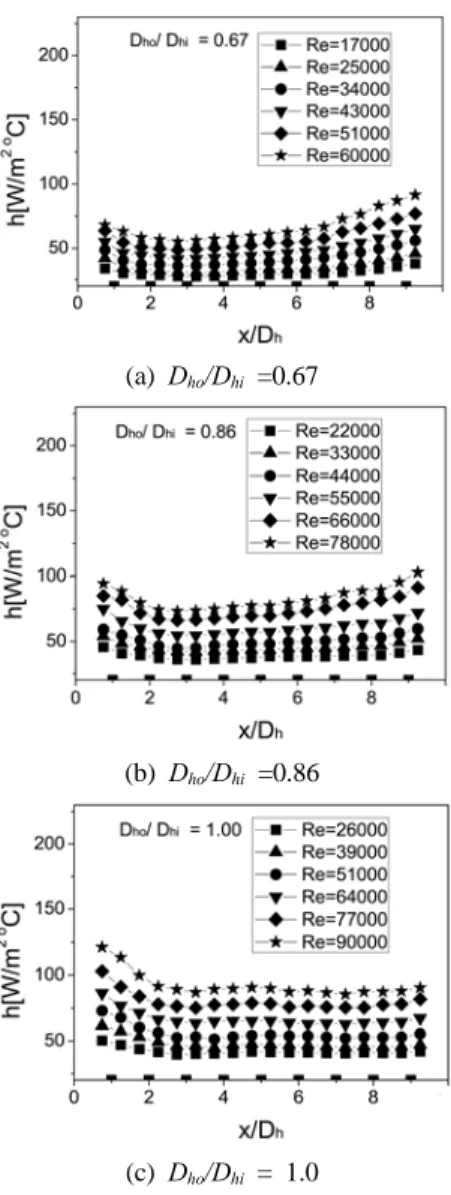
The present correlations have maximum deviations of 9% in friction factors. Fig. 3 indicates the local centerline convective heat transfer coefficients for the three different types of ribbed channels. By careful examination of these figures we may find the following characteristics:
(a) Dho/Dhi =0.67
(b) Dho/Dhi =0.86
(c) Dho/Dhi = 1.0
Fig. 3 Centerline local heat transfer coefficients
1) For all the ribbed channels, the local heat transfer coefficients show a monotonically increasing trend with the Reynolds number, with the increases rate of Dho/Dhi =1.0 being the highest at the mid
test section. 2) For the ribbed channel of straight square cross section, the heat transfer may be regarded as fully developed after 2-3 ribs, characterizing by almost the same level and variation pattern of the local heat transfer coefficient. It should be noted that the local heat transfer coefficient in the region close to the channel outlet exhibits an increasing trend. This is expected to have resulted from the end heat loss, which makes the wall temperatures nearby decrease to some extent. An additional heating element was used after the test section to balance the axial heat conduction from the test section to alleviate such a phenomenon. 3) For the rectangular convergent channels (Dho/Dhi = 0.67, 0.86) the local heat transfer coefficient keeps continuously increasing along the streamwise distance. it can be seen that at almost the same Reynolds number, the local heat transfer coefficients of the divergent channels are larger than those of the convergent channels and the constant cross-sectional channel. Fig. 4 compares the channel average Nusselt numbers against the ratio of Dho/Dhi on the ordinate with Reynolds number on the abscissa.
In the rectangular convergent channels (Dho/Dhi
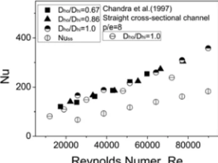
=0.67, 0.86) almost the same Nusselt numbers produce regardless of the ratio of Dho/Dhi. This is expected to have resulted from the flow acceleration at the lower Dho/Dhi, which leads both of the wall temperature and the air bulk temperature decrease and almost a constant in Nusset number to some extent. This is the contrary to the public opinion that the Nusselt number is generally proportional to the fluid velocity. The Dittus-Boelter’s correlation(Nuss) for the smooth tube is included for a comparison. Measured Nusselt number for this current work can be correlated by:
≤≤
(9)
Fig. 4 Channel average Nusselt numbers
The present correlations for Nusselt numbers have coincided with the experimental results within ±7%.
For a comparison, Fig. 4 includes the experimental results of Chandra et al. 6) , in which all four walls were heated in the test section. The Nusselt numbers in the present work of Dho/Dhi =1.0 were somewhat higher than those for Chandra et al. 6) It occurred that because the colder fluids from the two unheated walls moved toward the two heated walls, resulting in higher heat transfer coefficients in the present work. The Dittus-Boelter’s correlations (Nuss) for the fully developed turbulent smooth tube are included as a reference.
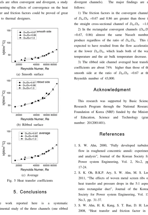
The Reynolds number dependences of the convective heat transfer coefficient for five types of ribbed channels are shown in Fig. 5. In Fig. 5(a) and (b), the ribbed side and the opposing smooth side heat transfer coefficients are presented, while the average heat transfer coefficients for the entire channel are shown in Fig. 5(c).
It can be seen that the ribbed side channel averaged heat transfer coefficients are about 74%
higher than those of the smooth side at the ratio of Dho/Dhi =0.67 at the Reynolds number of 43,000.
The major reason accounts for this fact that the heat transfer of a ribbed surface is enhanced by the existence of ribs which acts as turbulent promoters.
The current study tries to address a pertinent industrial issue by quantifying the effect of c onvergence and divergence in the ribbed channels.
Since geometrical constraints imply that the ribbed channels are often convergent and divergent, a study documenting the effects of convergence on the heat transfer and friction factors could be proved of great value to thermal designers.
(a) Smooth surface
(b) Ribbed surface
(c) Average
Fig. 5 Heat transfer coefficients
5. Conclusions
The work reported here is a systematic experimental study of the three channels (one ribbed
channel with straight cross section and two ribbed divergent channels). The major findings are as follows:
1) The friction factors in the convergent channels of Dho/Dhi =0.67 and 0.86 are greater than those in the straight cross-sectional channel of Dho/Dhi =1.0.
2) In the rectangular convergent channels (Dho/Dhi
=0.67, 0.86) almost the same Nusselt numbers produce regardless of the ratio of Dho/Dhi. This is expected to have resulted from the flow acceleration at the lower Dho/Dhi, which leads both of the wall temperature and the air bulk temperature decrease.
3) The ribbed side channel averaged heat transfer coefficients are about 74% higher than those of the smooth side at the ratio of Dho/Dhi =0.67 at the Reynolds number of 43,000.
Acknowledgment
This research was supported by Basic Science Research Program through the National Research Foundation of Korea (NRF) funded by the Ministry of Education, Science and Technology (grant number: 2012001401).
References
1. S. W. Ahn, 2000, “Fully developed turbulent flow in roughened concentric annuli: experiment and analysis”, Journal of the Korean Society for Power system Engineering, Vol. 2, No.2, pp.
17-24.
2. S. K. Oh, B.K.P. Ary, S. W. Ahn, M. S. Lee, 2011, “The effects of woven metal screen ribs on heat transfer and pressure drops in the 5:1 aspect ratio rectangular duct”, Journal of the Korean Society for Power system Engineering, Vol. 15, No.3, pp. 31-37.
3. S. W. Ahn, H. K. Kang, S. T. Bae, D. H. Lee, 2008, “Heat transfer and friction factor in a
square channel with one, two, or four inclined ribbed walls”, ASME Journal of Turbomachinery, Vol. 130, Turbo-06-1137, pp. 1-5.
4. L. B. Wang, W. Q. Tao, Q. W. Wang, T. T.
Wong, 2001, “Experimental study of developing turbulent flow and heat transfer in ribbed convergent/divergent square ducts”, International Journal of Heat and Fluid Flow, Vol. 22, pp.
603-613.
5. S. J. Kline, F. A. Mclintock, 1953, “Describing uncertainties in single sample experiments, Mechanical Engineering”, Vol.75, pp. 3-8.
6. P. R. Chandra, M. E. Niland, J. C. Han, 1997,
“Turbulent flow heat transfer and friction in a rectangular channel with varying numbers of ribbed walls”, ASME Journal of Turbomachinery, Vol. 119, pp. 374-380.