Introduction
Cone-beam computed tomography (CBCT) represents a highly promising and challenging advanced application using flat panel detectors.1,2The development of advanced imaging technology promises to increase the geometric precision of diagnostic procedures and finds applications
in oral and maxillofacial radiology and clinical dental pro- cedure.3,4 CBCT is an advanced application using flat panel detectors that is currently under investigation for use in various clinical approaches and image-guided proce- dures.5-11 CBCT can potentially result in images with a sub-millimeter spatial resolution and soft-tissue contrast detection.12,13
Since the imaging quality a diagnostic tool must be ade- quate for the diagnosis of lesions in the oral and maxillo- facial region, it is desirable to acquire images with a high image quality, showing adequate contrast-to-noise ratio performance and soft-tissue discrimination, while minimiz-
Received April 13, 2014; Revised June 2, 2014; Accepted June 9, 2014
*Correspondence to : Prof. Eui-Hwan Hwang
Department of Oral and Maxillofacial Radiology, School of Dentistry, Kyung Hee University, 1 Hoegi-dong, Dongdaemun-gu, Seoul 130-701, Korea
Tel) 82-2-958-9406, Fax) 82-2-965-1256, E-mail) [email protected]
http://dx.doi.org/10.5624/isd.2015.45.1.31
Copyright ⓒ 2015 by Korean Academy of Oral and Maxillofacial Radiology
This is an Open Access article distributed under the terms of the Creative Commons Attribution Non-Commercial License (http://creativecommons.org/licenses/by-nc/3.0) which permits unrestricted non-commercial use, distribution, and reproduction in any medium, provided the original work is properly cited.
Imaging Science in Dentistry∙pISSN 2233-7822 eISSN 2233-7830
Intravenous contrast media application using cone-beam computed tomography in a rabbit model
Min-Sung Kim1, Bok-Yeol Kim1, Hwa-Young Choi1, Yoon-Joo Choi1, Song-Hee Oh1, Ju-Hee Kang1, Sae-Rom Lee1, Ju-Han Kang1, Gyu-Tae Kim1, Yong-Suk Choi1, Eui-Hwan Hwang1,*
1Department of Oral and Maxillofacial Radiology, School of Dentistry, Kyung Hee University, Seoul, Korea
ABSTRACT
Purpose: This study was performed to evaluate the feasibility of visualizing soft tissue lesions and vascular struc- tures using contrast-enhanced cone-beam computed tomography (CE-CBCT) after the intravenous administration of a contrast medium in an animal model.
Materials and Methods: CBCT was performed on six rabbits after a contrast medium was administered using an injection dose of 2 mL/kg body weight and an injection rate of 1 mL/s via the ear vein or femoral vein under general anesthesia. Artificial soft tissue lesions were created through the transplantation of autologous fatty tissue into the salivary gland. Volume rendering reconstruction, maximum intensity projection, and multiplanar reconstruction images were reconstructed and evaluated in order to visualize soft tissue contrast and vascular structures.
Results: The contrast enhancement of soft tissue was possible using all contrast medium injection parameters. An adequate contrast medium injection parameter for facilitating effective CE-CBCT was a 5-mL injection before exposure combined with a continuous 5-mL injection during scanning. Artificial soft tissue lesions were successfully created in the animals. The CE-CBCT images demonstrated adequate opacification of the soft tissues and vascular structures.
Conclusion: Despite limited soft tissue resolution, the opacification of vascular structures was observed and artifi- cial soft tissue lesions were visualized with sufficient contrast to the surrounding structures. The vascular structures and soft tissue lesions appeared well delineated in the CE-CBCT images, which was probably due to the superior spatial resolution of CE-CBCT compared to other techniques, such as multislice computed tomography. (Imaging Sci Dent 2015; 45: 31-9)
KEY WORDS: Cone-Beam Computed Tomography; Contrast Media; Soft Tissue; Radiography
ing the dose of radiation required.3,4,11-13However, among the challenges in achieving high-resolution soft-tissue imaging are the limited dynamic range and contrast reso- lution of current CBCT techniques.13-15 The desire for a large field of view, in combination with the relatively large cross-sections required in clinical practice, requires that a CBCT apparatus has high detective quantum efficiency across a very broad range of exposure to the detector. The use of an additional contrast agent for increased soft tissue detection offers the potential ability for enhanced perfor- mance across the broad range of clinical applications of CBCT.
CBCT has been introduced into routine clinical practice as a new CT modality that provides cross-sectional ima- ges.2-5,7The flat panel detectors used in CBCT are much smaller than those used in multislice CT (MSCT).2,13 Therefore, these detectors have physical features that pro- vide excellent visualization in high-contrast structures with superior spatial resolution compared to MSCT.14-17 However, smaller detector elements receive proportion- ately lower photon flux, resulting in inferior contrast res- olution.2,13,17
The use of CBCT has therefore been limited due to low contrast resolution in soft tissue imaging. Only a few pub- lications have been published comparing CBCT with MSCT regarding the diagnostic capacities of these modal- ities in soft tissue imaging.14,15,17For the most part, intra- cranial hemorrhages have been investigated.14,15,18The use of intravenous (IV) contrast-enhancing materials during CBCT acquisition has rarely been reported, although some authors have used IV contrast enhancers to visualize intra- abdominal tumors or vascular lesions.18,19
Despite its limited soft tissue contrast resolution, CBCT provides substantially superior spatial resolution in com- parison with MSCT.14-17The superior spatial resolution of CBCT could lead to the enhanced visualization of soft tis- sue contrasts and small vascular structures, although a contrast-enhancing medium may be necessary to ensure substantial opacification and visibility of soft tissue and vessels. CBCT combined with the IV administration of a contrast-enhancing medium might, therefore, be a new tool in the diagnostic workup of soft tissue lesions in the oral and maxillofacial region. The purpose of this study was to evaluate the feasibility of visualizing soft tissue contrasts and vascular structures with contrast-enhanced CBCT (CE-CBCT) after IV injection of a contrast-enhanc- ing medium in an experimental animal model.
Materials and Methods
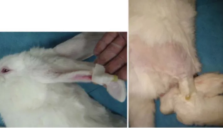
The study was approved by the Animal Protection Com- mittee of Kyung Hee University. Six New Zealand white rabbits (4-5 kg body weight) were used for this animal model. No previous studies have described the proper parameters of injecting the contrast medium (Iopamiro®, Ilsung Co., Seoul, Korea) for CBCT imaging. Therefore, experiments were performed using 2 mL/kg body weight, followed by a 6-mL saline flush with an injection rate of 1 mL/s via the ear vein or femoral vein under general anes- thesia, which was performed with a subcutaneous injec- tion of ketamine (80 mg/kg body weight) and Xylazine (7 mg/kg body weight) (Fig. 1). A preliminary examination was carried out to evaluate the effect of contrast enhance- ment in obtaining conventional radiography after the IV injection of the contrast medium. After the preliminary assessment, the following protocol was established for administering the contrast media for CBCT imaging. Three techniques were established for administering the contrast media. In Type 1, a 10-mL injection was administered for 10 seconds during CBCT scanning. Type 2 involved a 10- mL injection with a delay time of 30 seconds before CBCT scanning. Type 3 involved a 5-mL injection with a delay time of 20 seconds before CBCT scanning, combined with a 5-mL continuous injection during CBCT scanning.
Imaging was performed with a CBCT apparatus (Alph- ard Vega, Ashahi Roentgen Co., Kyoto, Japan). The expo- sure parameters were set at a tube voltage of 80 kVp, a tube current of 6 mA, and an exposure time of 17 seconds.
The exposure area was set to be 200 mm in diameter and 179 mm in height, with a voxel size of 0.39 mm. In this device, the X-ray source rotates 360 degrees around the
Fig. 1.A catheter is positioned for intravenous injection in New Zealand white rabbit.
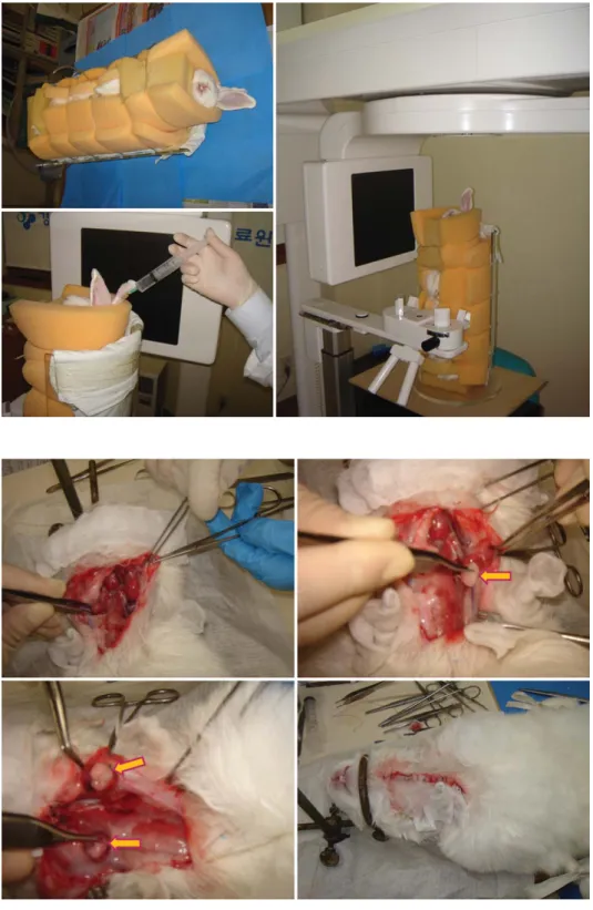
objects being imaged. The rabbits were immobilized by using specifically designed equipment that was construct- ed from acrylic resin for animal fixation (Fig. 2).
We created an experimental artificial soft tissue lesion model that has never been described previously. No pre- vious model had been used to simulate and investigate soft tissue lesions in the salivary gland for a CBCT study
in combination with the evaluation of vascular structures, such as the external carotid artery. The artificial lesions in the salivary gland were created in the submandibular glands (SMGs) of six New Zealand white rabbits, accord- ing to the following procedure. A vertical skin incision about 5 cm in length was made and both SMGs were ex- posed under general anesthesia, which was performed
Fig. 2.A specially designed equip- ment is used for immobilization of the rabbit during the procedures.
Fig. 3.The photographs show the procedure of an artificial lesion cre- ation in submandibular gland of the rabbit.
with a subcutaneous injection of ketamine (80 mg/kg body weight) and Xylazine (7 mg/kg body weight). Fatty tissue
was obtained from the adjacent fatty space that exists along the neck muscles. The transplantation of autologous
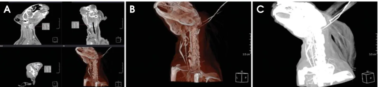
Fig. 4.Using the multiplanar reconstruction (A), volume rendering reconstruction (B), and maximum intensity projection (C) images, the measurements for the submandibular gland are performed.
Fig. 5.The window level and width of CBCT images are set at 0 and 1,000, respectively, in order to clarify the submandibular gland and the adjacent fatty space
Fig. 6.Effect of time-dependent intravenous contrast enhancement. A. before enhancement. B. 30 seconds after intravenous injection of 10 mL contrast medium. C. combination of continuous injection of 5 mL with 30 seconds delay time after 5 mL injection
A B C
A B C
fatty tissue into the salivary gland was performed after the incision of the SMGs and suturing using 4-0 absorbable surgical sutures. The skin was then closed using a 3-0 Polysorb running suture (Fig. 3).
The CBCT images were post-processed using a dedicat- ed workstation and OnDemand 3D software (CyberMed Inc, Seoul, Korea). We performed volume-rendering reco- nstruction (VRT) for three-dimensional imaging. Coronal maximum intensity projection (MIP) images with a 5-mm
slice thickness and 2.5-mm interposition were reconstruct- ed in order to visualize the external carotid arteries and nutrient vessels of the SMGs. Axial and coronal multipla- nar reconstructions (MPRs) with a 0.39-mm slice thickness were reformatted and used to perform measurements (Fig.
4). We tried to find matching slice positions, which was not entirely possible because each rabbit was positioned slightly differently. Post-image processing was performed on each dataset. The window level and width of CBCT
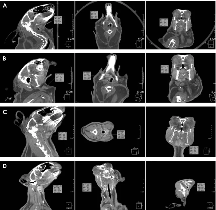
Fig. 7. The contrast density is measured on the non-enhanced CBCT images (A), type 1 enhanced CBCT image (B), type 2 enhanced CBCT image (C), and type 3 enhanced CBCT image (D).
A
B
C
D
images were set at 0 and 1,000, respectively, in order to clarify the SMGs and the adjacent fatty space (Fig. 5). The
reconstructions were anonymized for evaluation. Two experienced oral and maxillofacial radiologists indepen- dently evaluated the CBCT images for soft tissue contrast and vascular structure anatomy, using standard tools and software at a dedicated workstation.
Results
First, we conducted a preliminary examination to eval- uate the effect of IV contrast enhancement on obtaining conventional radiography after the IV injection of the contrast medium. Static radiography images were taken after IV injection of the contrast medium according to the various experimental methods. One method involved a radiographic exposure with a delay time of 30 seconds after the IV injection of 10 mL of contrast medium. In the second method, a radiographic exposure was performed in combination with a continuous injection of 5 mL of contrast medium, 30 seconds after a 5-mL injection. The former radiograph revealed the circulation of contrast media through the heart, with weak visualization of the carotid arteries. The latter radiograph revealed an accumu-
Fig. 9.A. The CBCT images show the difference of value of contrast density before and after contrast media administration for the artificial lesion in salivary gland by transplantation of autogenous fatty tissue. B. The graph shows the comparison of contrast density between non-enhancement and type 3 contrast enhancement in salivary gland and artificial fatty lesion on the CBCT image.
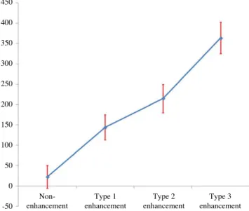
Fig. 8.The graph shows the contrast density in CBCT according to the study protocol of the contrast media administration for con- trast enhancement.
450 400 350 300 250 200 150 100 50 0 -50
Non- Type 1 Type 2 Type 3
enhancement enhancement enhancement enhancement
Non-enhanced CBCT Type-3 enhanced CBCT
A
B
lation of the contrast medium in the kidneys and promi- nent visualization of the carotid arteries (Fig. 6). There- fore, we were able to adopt a study protocol investigating different administrations of the contrast medium for CBCT, as discussed above.
CBCT imaging data was obtained from every animal in all of the experimental conditions that we investigated.
Post-image processing was performed successfully for all datasets. Opacification of the vascular structures and con- trast enhancement of the SMGs were evaluated in MPRs by calculating the contrast density in the region of inter- est in the CBCT image. The mean contrast density of the SMGs in non-enhanced CBCT was 22, with a standard deviation (Std) of 28, a minimum (Min) value of -45 and a maximum (Max) value of 83 (Fig. 7A). The mean con- trast density value of Type 1 CE-CBCT images was 144 (Std, 31; Min, 31; Max, 197) (Fig. 7B). The mean contrast density value of Type 2 CE-CBCT images was 215 (Std, 35; Min, 134; Max, 301) (Fig. 7C) and the mean contrast density value of Type 3 CE-CBCT images was 364 (Std, 39; Min, 254; Max, 471) (Fig. 7D).
The anatomy of the carotid arteries and the nutrient ves- sels to the SMGs in the neck region was clearly visible in all modalities. Subsequently, both reviewers determined that all VRT images obtained by CBCT were of good dia- gnostic quality. Type 3 reconstructed CBCT MIP images were assessed to evaluate variation among the different methods of administrating the contrast medium. The deli- neation of vessels and SMGs was sharper in Type 3 ima- ges, and therefore the borders of the nutrient vessels and the anatomy of the SMGs were much more visible, indi- cating sharp contrast enhancement. The results of the measurements are given in Figure 8.
An artificial soft tissue lesion was successfully created in all six animals. None of the animals presented with any clinical abnormalities. The contrast enhancement of soft tissue was observed in all administrations of contrast medi- um. However, the optimal administration of contrast media for CE-CBCT was a 5-mL injection before exposure with a continuous 5-mL injection during scanning (Type 3 CE- CBCT). The contrast density values for the artificial lesion within the SMGs and the vascular structures of the carotid arteries and the nutrient vessels were nearly identical in all three modalities. However, sufficient opacification of the soft tissues and vascular structures only occurred in the Type 3 CE-CBCT procedure. The anatomy of the artificial soft tissue lesions was clearly visible. The contrast den- sity value of the SMGs changed from 32 in non-enhanced
CBCT to 319 in Type 3 CE-CBCT, while the contrast value of the artificial fatty lesions changed from -154 in non-enhanced CBCT to -125 in Type 3 CE-CBCT. The results of the measurements are given in Figure 9.
Discussion
CBCT using a flat panel detector is an alternative meth- od of obtaining cross-sectional images.1-4The idea of per- forming CBCT with the IV administration of a contrast medium in order to improve its imaging capacity is a straightforward development of existing techniques.18-21 The well-known superior spatial resolution of CBCT may facilitate the visualization of small vascular structures or soft tissue in oral and maxillofacial lesions.21 However, its inferior soft tissue resolution might limit the observ- able contrast between opacified vascular structures and the surrounding tissue.17,19,20To the best of our knowledge, no study has yet been published evaluating CBCT images of salivary gland lesions after the IV administration of a contrast-enhancing medium.
Limited studies have been performed assessing the ad- ministration and visualization of IV contrast material in CBCT.19-21The present study provided an in vivo evalua- tion of CBCT in an animal model. Our idea was to show that the visualization of vascular structures using CE-CB CT should be possible, despite the limited contrast reso- lution of CBCT. Our observations indicated that the visu- alization of the investigated structures appeared nearly identical in all imaging modalities including VRT, MIP, and MPR. Although small structures were investigated, we were at the margins of diagnostic accuracy. Therefore, we do not suggest that any one modality was superior to the others. The three modalities provide an almost equal visualization of the dimensions of the investigated struc- tures. However, structures in the reconstructed VRT ima- ges were relatively hard to distinguish, compared to those in the MIP and MPR images. The margins of the SMGs and vascular structures were more sharply delineated in the MPR and MIP reconstructions of CBCT imaging, probably due to its superior spatial resolution and limited soft tissue resolution.
The dosage and timing of contrast material administra- tion were critical. Although no previous study has indicat- ed the proper techniques for this experimental setup, we used a standard dose of 2 mL/kg body weight and consis- tent CBCT injection parameters. Our aim was to demon- strate that a standard dose and administration method of
contrast material would provide sufficient opacification of vascular structures, allowing the arteries and soft tissues to be visualized. The dose of 2 mL/kg body weight is com- parable to injection protocols in human beings and has also been used in other animal studies on rabbits.22Con- trast medium administration using the Type 3 protocol (5- mL injection and 20-second delay time, with a 5-mL con- tinuous injection during CBCT scanning) was sufficient despite the acquisition time of 17 seconds in the CBCT apparatus. The contrast enhancement was visible in all animals. It may be useful for future studies to investigate the optimal timing, amount, and concentration of contrast material.
An advantage of CBCT technology is that it involves a reduced radiation dose compared to conventional CT.23-25 However, CBCT images have several types of noise, espe- cially in the central portion of the field of view. In addi- tion, CBCT images are low-contrast, and motion artifacts, which are mainly caused by inadequate breath-holding, can cause the image quality to deteriorate.17,26 Artifacts from the catheter, contrast material in the vessels, or densely accumulated iodized contrast medium can also been seen.27,28 An advanced algorithm and a faster scan- ning protocol may be needed to improve the image quali- ty by reducing these image artifacts.27Therefore, further comparative studies of CBCT, MSCT, and other imaging techniques are necessary to evaluate the radiation dose and diagnostic quality with regard to the visualization of vascular structures and soft tissue lesions before this new method can be recommended to patients as a routine pro- cedure. Evidence seems to suggest that CBCT is associ- ated with either a higher or lower radiation dose than MSCT, depending on the CBCT program used.29,30 This also needs further investigation.
Our study had multiple shortcomings. The sample size of six rabbits was small, but sufficient to demonstrate fea- sibility in this preliminary study. Signal ratios were usual- ly used to compare contrast values. Because the measure- ment of Hounsfield units is not yet possible in CBCT, it was not possible to provide a comparison of signal ratios.
Thus, our impressions of CBCT contrast values were somewhat subjective. Another limitation of the study may be the lack of histological tests to validate the measure- ments. CE-CBCT has not been broadly applied for clini- cal purposes,, but broader implementation would be nec- essary to optimize contrast application in patients.
In conclusion, this study demonstrated the feasibility of CE-CBCT used instead of simple CBCT in a rabbit model.
Despite its limited soft tissue contrast resolution, it was
possible to visualize the opacification of vascular struc- tures and the presence of an artificial soft tissue lesion with sufficient contrast to the surrounding structures. The vascular structures and soft tissue lesions were clearly visualized in the CE-CBCT images, which probably due to the superior spatial resolution of this technique.
References
1. Kalender WA, Kyriakou Y. Flat-detector computed tomogra- phy (FD-CT). Eur Radiol 2007; 17: 2767-79.
2. Kalender WA. The use of flat-panel detectors for CT imaging.
Radiologe 2003; 43: 379-87.
3. Scarfe WC, Farman AG, Sukovic P. Clinical applications of cone-beam computed tomography in dental practice. J Can Dent Assoc 2006; 72: 75-80.
4. Kapila S, Conley RS, Harrell WE Jr. The current status of cone beam computed tomography imaging in orthodontics.
Dentomaxillofac Radiol 2011; 40: 24-34.
5. Yu JJ, Kim GT, Choi YS, Hwang EH, Paek J, Kim SH, et al.
Accuracy of a cone beam computed tomography-guided sur- gical stent for orthodontic mini-implant placement. Angle Orthod 2012; 82: 275-83.
6. Kim SH, Kang SM, Choi YS, Kook YA, Chung KR, Huang JC. Cone-beam computed tomography evaluation of mini- implants after placement: is root proximity a major risk factor for failure? Am J Orthod Dentofacial Orthop 2010; 138: 264- 76.
7. Tyndall DA, Rathore S. Cone-beam CT diagnostic applica- tions: caries, periodontal bone assessment, and endodontic applications. Dent Clin North Am 2008; 52: 825-41.
8. Kim GT, Kim SH, Choi YS, Park YJ, Chung KR, Suk KE, et al. Cone-beam computed tomography evaluation of orthodon- tic miniplate anchoring screws in the posterior maxilla. Am J Orthod Dentofacial Orthop 2009; 136: 628.e1-10.
9. Choi HS, Kim GT, Choi YS, Hwang EH. Surgical stent for dental implant using cone beam CT images. Korean J Oral Maxillofac Radiol 2010; 40: 171-8.
10. Kim SH, Choi YS, Hwang EH, Chung KR, Kook YA, Nelson G. Surgical positioning of orthodontic mini-implants with guides fabricated on models replicated with cone-beam com- puted tomography. Am J Orthod Dentofacial Orthop 2007;
131: S82-9.
11. Vercruyssen M, Jacobs R, Van Assche N, van Steenberghe D.
The use of CT scan based planning for oral rehabilitation by means of implants and its transfer to the surgical field: a critical review on accuracy. J Oral Rehabil 2008; 35: 454-74.
12. Jin JY, Ren L, Liu Q, Kim J, Wen N, Guan H, et al. Combin- ing scatter reduction and correction to improve image quality in cone-beam computed tomography (CBCT). Med Phys 2010; 37: 5634-44.
13. Miracle AC, Mukherji SK. Conebeam CT of the head and neck, part 1: physical principles. AJNR Am J Neuroradiol 2009; 30: 1088-95.
14. Struffert T, Richter G, Engelhorn T, Doelken M, Goelitz P, Kalender WA, et al. Visualisation of intracerebral haemor-
rhage with flat-detector CT compared to multislice CT: results in 44 cases. Eur Radiol 2009; 19: 619-25.
15. Doelken M, Struffert T, Richter G, Engelhorn T, Nimsky C, Ganslandt O, et al. Flat-panel detector volumetric CT for visu- alization of subarachnoid hemorrhage and ventricles: prelim- inary results compared to conventional CT. Neuroradiology 2008; 50: 517-23.
16. Naitoh M, Nakahara K, Suenaga Y, Gotoh K, Kondo S, Ariji E. Comparison between cone-beam and multislice computed tomography depicting mandibular neurovascular canal struc- tures. Oral Surg Oral Med Oral Pathol Oral Radiol Endod 2010; 109: e25-31.
17. Watanabe H, Honda E, Tetsumura A, Kurabayashi T. A com- parative study for spatial resolution and subjective image characteristics of a multi-slice CT and a cone-beam CT for dental use. Eur J Radiol 2011; 77: 397-402.
18. Engelhorn T, Struffert T, Richter G, Doelken M, Ganslandt O, Kalender W, et al. Flat panel detector angiographic CT in the management of aneurysmal rupture during coil emboliza- tion. AJNR Am J Neuroradiol 2008; 29: 1581-4.
19. Meyer BC, Frericks BB, Albrecht T, Wolf KJ, Wacker FK.
Contrast-enhanced abdominal angiographic CT for intra- abdominal tumor embolization: a new tool for vessel and soft tissue visualization. Cardiovasc Intervent Radiol 2007; 30:
743-9.
20. Meyer BC, Frericks BB, Voges M, Borchert M, Martus P, Justiz J, et al. Visualization of hypervascular liver lesions dur- ing TACE: comparison of angiographic C-arm CT and MDCT.
AJR Am J Roentgenol 2008; 190: W263-9.
21. Struffert T, Doelken M, Adamek E, Schwarz M, Engelhorn T, Kloska S, et al. Flat-detector computed tomography with intravenous contrast material application in experimental aneurysms: comparison with multislice CT and conventional angiography. Acta Radiol 2010; 51: 431-7.
22. Kallmes DF, Helm GA, Hudson SB, Altes TA, Do HM, Mandell JW, et al. Histologic evaluation of platinum coil embolization in an aneurysm model in rabbits. Radiology
1999; 213: 217-22.
23. Qu XM, Li G, Ludlow JB, Zhang ZY, Ma XC. Effective radi- ation dose of ProMax 3D cone-beam computerized tomogra- phy scanner with different dental protocols. Oral Surg Oral Med Oral Pathol Oral Radiol Endod 2010; 110: 770-6.
24. Carrafiello G, Dizonno M, Colli V, Strocchi S, Pozzi Taubert S, Leonardi A, et al. Comparative study of jaws with multislice computed tomography and cone-beam computed tomography.
Radiol Med 2010; 115: 600-11.
25. Suomalainen A, Kiljunen T, Käser Y, Peltola J, Kortesniemi M. Dosimetry and image quality of four dental cone beam computed tomography scanners compared with multislice computed tomography scanners. Dentomaxillofac Radiol 2009; 38: 367-78.
26. Ritter L, Mischkowski RA, Neugebauer J, Dreiseidler T, Scheer M, Keeve E, et al. The influence of body mass index, age, implants, and dental restorations on image quality of cone beam computed tomography. Oral Surg Oral Med Oral Pathol Oral Radiol Endod 2009; 108: e108-16.
27. Miyayama S, Yamashiro M, Hattori Y, Orito N, Matsui K, Tsuji K, et al. Efficacy of cone-beam computed tomography during transcatheter arterial chemoembolization for hepato- cellular carcinoma. Jpn J Radiol 2011; 29: 371-7.
28. Miyayama S, Matsui O, Yamashiro M, Ryu Y, Takata H, Takeda T, et al. Detection of hepatocellular carcinoma by CT during arterial portography using a cone-beam CT technology:
comparison with conventional CTAP. Abdom Imaging 2009;
34: 502-6.
29. Kyriakou Y, Richter G, Dörfler A, Kalender WA. Neuroradi- ologic applications with routine C-arm flat panel detector CT:
evaluation of patient dose measurements. AJNR Am J Neuro- radiol 2008; 29: 1930-6.
30. Struffert T, Hertel V, Kyriakou Y, Krause J, Engelhorn T, Schick B, et al. Imaging of cochlear implant electrode array with flat-detector CT and conventional multislice CT: com- parison of image quality and radiation dose. Acta Otolaryngol 2010; 130: 443-52.