• 검색 결과가 없습니다.

Fabrication of Multi-Layered Graphenes/P(S-co-BA) Nanocomposite via Sudden Heating Heterocoagulation Process

N/A
N/A
Protected

Academic year: 2021

Share "Fabrication of Multi-Layered Graphenes/P(S-co-BA) Nanocomposite via Sudden Heating Heterocoagulation Process"

Copied!
8
0
0

로드 중.... (전체 텍스트 보기)

전체 글

(1)

Fabrication of Multi-Layered Graphenes/P(S- co-BA) Nanocomposite via Sudden Heating Heterocoagulation Process

JinKyu Choi, Eun-Kyoung Lee * , and Sang Eun Shim

Department of Chemistry & Chemical Engineering, Inha University, 100 Inha-ro, Namgu, Incheon 22212, Republic of Korea

*

Department of Biomedical Science, Cheongju University, Chungju 28503, Republic of Korea (Received November 3, 2017, Revised November 21, 2017, Accepted November 24, 2017)

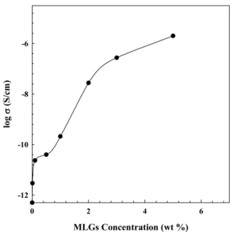
Abstract: The heterocoagulation of latex is a simple and useful method to fabricate various polymer nanocomposites in which a precise control of the colloid stability is essential. In this work, a multi-layered graphenes (MLGs)/poly(styrene- co-butyl acrylate) (P(S- co-BA)) nanocomposite having an excellent dispersion of MLGs was prepared via the sudden heat- ing heterocoagulation process. The P(S- co-BA) component was obtained by emulsion polymerization. This process can effectively shorten the process and particles growth steps. The colloid stability of these dispersions was controlled by factors such as ionic charge, temperature, and reaction times. The influence of these factors on heterocoagulation was evaluated and the properties of the nanocomposites were investigated. The conductivity of the MLGs/P(S- co-BA) nanocomposites increased from −11.53 to −5.70 S/cm for an increase in MLG content from 0.01 to 5 wt%. Moreover, percolation threshold was observed in the case of 0.01 wt% MLGs.

Keywords: multi-layered graphene, latex, sudden heating heterocoagulation process, percolation threshold, electrical con- ductivity

Introduction

Agglomeration of latex is the fundamental method used in various processes such as pigment formulation, water puri- fication, and drug delivery system, etc. These processes are indispensable to have a precise control over the colloid sta- bility and they are of technical as well as scientific impor- tance. The colloid stability of these dispersions is controlled by factors such as particle diameter, ionic charge, and the concentration of stabilizers.

1

Colloidal particle properties, agglomeration action, mutual interaction, and charging effects have been studied well among spherical particles, rods, and spheres. However, they still have challenging problems.

2-6

Aqueous dispersions of charged colloids have been the goal of strong investigations recently. Different composites have been prepared by heterocoagulation on the surfaces between small latex particles having a low T

g

and large poly- mer particles having a high T

g

. But their charges are opposite each other.

7,8

Heterocoagulation generate a stable composite particle that is driven by electrostatic interactions of oppo- sitely charged materials. Composite particles with well-defined

morphologies can be made via heterogoagulation process either by engulfment or complete encapsulation.

9,10

Various carbonaceous materials including graphene, car- bon nanotube, diamond, graphite, and buckyball have been researched in diverse regions of nanomaterial.

11

So far, car- bon-based materials have been applied to nanocomposites, field effect transistors, quantum devices, chemical-bio sen- sors, and so on.

12-14

But most of all, graphene is a remarkable material for a zero-bandgap semiconductor giving electric field effect.

15

Electric characters of graphene were investi- gated about the transport of relativistic Dirac fermions, spin transports, bipolar supercurrents, and quantum Hall effects at room temperature for a few years.

16-18

It has been applied to other fields as in ambipolar field effect transistor, ultrasen- sitive gas sensor, gate controlled p-n junction, nanoribbon, and building block for carbon-based integrated nanoelec- tronics, etc.

19-21

It is difficult to niformly disperse MLGs in host matrices as a filler in polymers because MLGs tend to easily self- agglomerate by strong van der Waals force.

22

The adhesion and wettability with matrix must be maximized to solve this self-agglomeration problem which can be accomplished by

Corresponding author E-mail: [email protected]

(2)

the physical treatment of MLGs such as surfactant addition.

Because the physical treatment process is easy and the prop- erties and structure of MLGs are not affected by chemical treatment during reaction step. The physical treatment becomes advantageous for the heterocoagulation of MLGs than the chemical treatment. In this experiment, physical treatment process was adopted to MLGs dispersion for this reason.

23,24

In the previous research, reaction time takes several hours to form the agglomeration particles via heterocoagulation.

25,26

The percolation threshold was observed at a low concentra- tion of MLGs.

27-30

But in this work, SBA latex (styrene-co- butyl acrylate) films were prepared via sudden heating het- erocoagulation process (SHHP) with positively charged MLGs and negatively charged SBA latex that has low T

g

. This method is a fast and easy production process that has a very short reaction time. The morphology of composites was formed from unshaped to spherical particles via SHHP of P(S-co-BA) and MLGs. The dispersion and electrical pro- perties of the prepared MLGs/P(S-co-BA) nanocomposites were investigated.

Experimental

1. Materials

Sodium hydroxide (NaOH) (Duksan pure chemical, Korea), 1-dodecanethiol (Acros Organics, 98.5+ %), multi-layered graphene (NBT Co. Ltd., Korea.), styrene (Junsei, Samchun Chemical, Korea), potassium persulfate (KPS) (Aldrich), magnesium chloride (MgCl

2

) (Acros Organics), hexadecyl trimethylammonium bromide (CTAB) (Acros organics, 99+

%), butyl acrylate (Samchun Chemical, Korea), and sodium dodecyl sulfate (SDS) (Acros Organics, 85%) were used in this experiment.

2. Preparation of MLGs dispersions

0.01, 0.1, 0.5, 1, 2, 3, and 5 wt.% MLGs were dispersed into CTAB-added water. The c.m.c of CTAB in water is 9×10

−4

M at 25

o

C. The mixture was dispersed by ultra son- icator (Sonics & Materials INC.) with 300 watt for 10 min in cool bath.

3. Synthesis of latex via emulsion polymerization

P(S-co-BA) particles were synthesized via emulsion poly-

merization at 70

o

C for 24 hrs under N

2

gas. 300 ml water, 12 g BA, 18 g Styrene, 0.681 g SDS (at c.m.c), 0.9 g 1- dodecanethiol, and 0.2 g KPS were put into 500 ml three- neck round flask.

4. Preparation of flocculant and dispersion solution

0.1 M MgCl

2

solution was prepared as flocculant and 1 M NaOH solution were used for dispersant of particles.

5. Sudden heating heterocoagulation process (SHHP)

Various wt % MLGs dispersion was added into 200 g SBA latex at 6,000 rpm at 25

o

C via a homogenizer. And 2.0 g MgCl

2

(0.1 M) solution as flocculant was added into the mix- ture then it turned to slurry. After the change to slurry, it was smashed by homogenizer at 14,000 rpm at 25

o

C for 5 min.

The pH of mixture turned from pH 2 to pH 11 for 30 min after addition of 0.7 ml NaOH (0.1 M) pH at 25

o

C. Next step was to move the mixture into a jacket reactor that already heated at 80

o

C for 5 min at 200 rpm. After the sudden heat- ing for formation of spherical morphology, it was quickly cooled via quenching.

6. Film formation

After the dry of the moisture of composites at 40

o

C on tef- lon plate, it was fully dried into vacuum oven at 60

o

C for 48 hrs for the film formation.

7. Characterization

The size and distribution of particles were measured via particle size analyzer (Coulter LS-230

®

, Beckman Coulter, USA). The morphology of the particles was measured via transmission electron microscope (CM200, Philips) and the scanning electron microscope (S-4300, Japan). The molec- ular weight of P(S-co-BA) particles was measured with GPC (Viscotek VE series, USA). T

g

was measured via differential scanning calorimeter (DSC200F3, Netzsch, Germany). The electric conductivity of films was measured via resistivity machine (Hiresta-UP, Mitsubishi Chemical/520 Co., Japan).

Results and Discussion

The purpose of this experiment is to make the nanocompo-

(3)

sites with SBA latex and MLGs dispersed uniformly via het- erocoagulation which agglomerates with the oppositely charged particles without the self-agglomeration of each MLG. Fur- thermore, this method has an advantage that it will not change the natural properties of MLGs. In the previous researches, the formation times of composites were taken several hours for spherically-shaped particles via heterocoagulation.

31,32

But, in this work, the formation times of nanocomposites were taken only 5 min via sudden heating heterocoagulation process (SHHP). The properties of SBA latex were summarized in Table 1. The results were that the conversion of 98%, the mean diameter of 90 nm, and the zeta potential of −20.4 mV at pH 1.9 of latex.

Next results are the effects of pH, temperatures and reac- tion times for the formation of spherical particles with SBA latex and MLGs via SHHP.

1. Effect of pH

In Figure 1(b), the zeta potential of latex goes up with the increase of pH value. They have a lower mean diameter at high absolute value of zeta potential than the mean diameter of composites at lower zeta potential since they have the

better colloid stability; the more distant from the ZPC (zero point charge) as repulsive power with same ionic charge.

33

The pH of mixture was adjusted from 1.9 up to 9.5. Because SBA latex had a relatively low T

g

. Otherwise particles will agglomerate due to the contact of particles which have sticky surfaces. As seen in Figure 2, mean diameter of particles was 50 mm before the control of NaOH. On the other hand, mean diameter of particles was 25 mm after the control of NaOH.

The reason of a mean diameter change is an influence of increased pH after the addition of NaOH.

2. Effect of Temperature

Temperature is a major factor for the formation of the mor- phology in spherical shape. The morphology of nanocompo- sites changes by the reaction temperature shown in Figure 3.

Various morphologies were observed; (a) rough shape at 60

o

C, (b) potato shape at 70

o

C, and (c) spherical shape at 80

o

C. SBA latex had thermodynamically unstable tendency by addition of flocculent to shape the spherical morphology by the temperature increase.

Mean diameter grows with the increase of reaction tem- perature as proved by the results obtained from a particles size analyzer. The diameter change by temperature was men- tioned in Figure 4; 45.15 mm at 60

o

C, 64.78 mm 70

o

C, and 79.86 mm 80

o

C. Unreacted small particles are observed under 8 mm diameter at 60

o

C. However, they almost disappeared at 70

o

C and could not be observed at 80

o

C. This explains that unreacted small particles were agglomerated as nanocompo- sites by the heating of mixture. As the temperature increases, the SBA latex particles become softer, which accelerating the heterocoagulation.

3. Effect of Process Time

For the following experiments, temperature and process time were chosen at 80

o

C and 5 min, respectively. The SEM image in Figure 5 shows that the growth and change of the morphology of the nanocomposite particles up to 5 min. As the process time increases, the morphology changed from irregular and potato to spherical shape at 5 min. It can be Table 1. Properties of SBA Latex Produced via Emulsion Polymerization.

Conversion (%)

Mean Diameter (nm)

Zeta Potential (mV)

T

g

(

o

C)

M

w

(g/mol)

M

n

(g/mol) PDI

98 90 -20.4 29.1 37,000 5,700 6.4

Figure 1. Effect of pH on the zeta potential for (a) MLGs with

CTAB in DI water and (b) SBA latex.

(4)

achieved within very short time which is a new breakthrough compared to previous process.

32

In this process, the inter- mediate heating process was removed and mixture was moved into a heated reactor. The reaction time which was several hours in previous process was reduced just for a few minutes.

4. Dispersion of MLGs in Nanocomposite Particles

Figure 6 is TEM and SEM images of (a) raw MLGs and (b) the cross-section of MLGs/ P(S- co-BA) nanocomposites.

In Figure 6(b) and (c), it is observed that MLGs and SBA Figure 2. SEM image of SBA latex/MLGs composites at 25 ℃ (a) before the addition of NaOH (b) after the addition of NaOH.

Figure 3. SEM photographs of MLGs/P(S-co-BA) nanocomposite particles at (a) 60, (b) 70, (c) 80℃ for 5 min reaction time.

(5)

latex were well agglomerated to form uniformly dispersion of MLGs. The cross-section of SEM image of a MLGs/P(S- co-BA) film represents that MLGs were well dispersed in the

matrix because MLGs and SBA latex have opposite charges on their surfaces. For this reason, this experiment can be a heterocoagulation process.

Figure 4. Particle size distributions MLGs/P(S- co-BA) nanocomposite particles at (a) 60, (b) 70, and (c) 80℃.

Figure 5. SEM photographs of MLGs/P(S- co-BA) nanocomposite particles with different reaction time for (a) 0, (b) 1, (c) 2, (d) 3, (e) 4, and (f) 5 min at 80 ℃.

Figure 6. TEM photographs of (a) raw MLG and (b) MLGs/P(S- co-BA) nanocomposite particles for 5 min at 80℃. (c) SEM image of

the cross-section of the nanocomposites film.

(6)

5. Electrical and Thermal Properties of Nanocomposites

Electrical conductivity of carbon materials shows an abrupt increase due to the formation of three-dimensional conduc- tive network of the filler in polymer matrix which can be explained by percolation theory. When a critical filler content approaches, the conductivity increases by the segregated net- work concept.

27

Usually, the percolation threshold concentration of carbon nanotubes or graphenes in polymers are usually in the range of 3.0-5.0 wt% by dry blending method. However,

the percolation was witnessed only at 0.01 wt% in Figure 7.

The conductivity of MLGs/P(S-co-BA) nanocomposites increases from −11.53 to −5.70 S/cm with a corresponding increase of MLGs from 0.01 to 5 wt%. This relatively high conductivity is originated from the large surface area of MLGs compared to carbon nanotubes.

32,33

Figure 8 indicates the thermal stability of MLGs/P(S-co- BA) nanocomposites containing different content of MLGs where the major weight loss was monitored in the range of 350~500

o

C. Fast weight losses take place around 400

o

C and the complete decompositions occur above 500

o

C. As seen in the thermograms, the thermal stability of nanocomposites is enhanced due to the strong interaction between MLGs and P(S-co-BA) due to improved dispersion state.

Conclusions

This work aimed to fabricate MLGs/P(S-co-BA) nano- composites by sudden heating heterocoagulation process without the self-agglomeration of MLGs. Also, this SHHP does not change the natural properties of MLGs. The reaction time of nanocomposites forming spherical shape was taken only 5 min because of the elimination of the unnecessary reaction step and minimizing particles growth step. In addi- tion, the agglomeration of particles is greatly influenced by pH adjustment, temperature, and reaction time. As the reaction time, namely growth step, increases, the shape of the nano- composite particles turns from irregular to spherical shape with particle size in the range of 50~80 mm. It is noted that no primary SBA latex particles were observed after hetero- coagulation process. Furthermore, the MLGs were evenly distributed in P(S- co-BA) matrix. The percolation threshold of MLGs was identified around 0.01 wt% which is very low compared to conventional compounding process. Furthermore, the thermal stability of the nanocomposite increased by the increased amount of MLGs.

Acknowledgements

The work was supported by Korea Industrial Technology Association (grant no.: 1711048189/KOITA-2016-7).

References

1. E. Tombacz, C. Csanaky, and E. Illes, “Polydisperse fractal aggregate formation in clay mineral and iron oxide suspensions, Figure 7. The electrical conductivity of MLGs/P(S- co-BA)

nanocomposite films prepared via SHHP.

Figure 8. TGA thermograms of virgin SBA latex and MLGs/P(S-

co-BA) nanocomposite films.

(7)

pH and ionic strength dependence”, Colloid Polym. Sci., 279, 484 (2001).

2. B. Vincent, C. A. Young, and T. F. Tadros, “Equilibrium aspects of heteroflocculation in mixed sterically-stabilised dispersions”, Faraday Discuss. Chem. Soc., 65, 296 (1978).

3. T. Serizawa, K. Taniguchi, and M. Akashi, “Hetero-coagula- tion of polymeric core-corona microspheres”, Colloids Surf.

A, 169, 95 (2000).

4. K. Maruyama, M. Kawaguchi, and T. Kato, “Heterocoagula- tion behavior of poly(styrene-co-butadiene) and poly(butyl acrylate) at high particle concentrations”, Colloids Surf. A, 189, 211 (2001).

5. W. B. Russel, D. A. Saville, and W. R. Schowalter, “Colloidal dispersions”, Cambridge University Press, Cambridge, 1992, Chapter 1, pp. 4-20.

6. R. J. Hunter, “Introduction to modern colloid science”, Oxford University, Sydney, 1994, pp. 35-45.

7. K. Yamaguchi, M. Ito, T. Taniguchi, S. Kawaguchi, and K.

Nagai, “Preparation of functional core-shell particles by het- erocoagulation”, Chem. Lett., 31, 1188 (2002).

8. K. Yamaguchi, M. Ito, T. Taniguchi, S. Kawaguchi, and K.

Nagai, “Preparation of core-shell composite polymer particles by a novel heterocoagulation based on hydrophobic interac- tion”, Colloid Polym. Sci., 282, 366 (2004).

9. J. A. Waters, “Composite particle dispersions”, European Pat- ent 0327199 (1990).

10. D. J. Voorn, W. Ming, A. M. van Herk, P. M. Frederik, P. Gas- emjit, and D. Johanssmann, “Controlled heterocoagulation of platelets and spheres”, Langmuir, 21, 6950 (2005).

11. A. K. Geim, K. S. Novoselov, “The rise of graphene”, Nat.

Mater., 6, 183 (2007).

12. S. J. Tans, A. R. M. Verschueren, and C. Dekker, “Room-tem- perature transistor based on a single carbon nanotube”, Nature, 393, 49 (1998).

13. A. Bachtold, P. Hadley, T. Nakanishi, and C. Dekker, “Logic circuits with carbon nanotube transistors”, Science, 294, 1317 (2001).

14. P. G. Collins, K. Bradley, M. Ishigami, and A. Zettl, “Extreme oxygen sensitivity of electronic properties of carbon nano- tubes”, Science, 287, 1801 (2000).

15. K. S. Novoselov, A. K. Geim, S. V. Morozov, D. Jiang, I. V.

Grigorieva, and A. A. Firsov, “Electric field effect in atomi- cally thin carbon films”, Science, 306, 666 (2004).

16. Y. Zhang, Y. W. Tan, H. L. Stormer, and P. Kim, “Experimen- tal observation of the quantum Hall effect and Berry's phase in graphene”, Nature, 438, 201 (2005).

17. K. S. Novoselov, Z. Jiang, Y. Zhang, S. V. Morozov, H. L.

Stormer, U. Zeithler, J. C. Maan, G. S. Boebinger, P. Kim, and A. K. Geim, “Room-temperature quantum Hall effect in

graphene”, Science, 315, 1379 (2007).

18. H. B. Heersche, H. Jarillo-Herrero, J. B. Oostinga, L. M. K.

Vandersypen, and A. F. Morpurgo, “Bipolar supercurrent in graphene”, Nature, 446, 56 (2007).

19. B. Ozyilmaz, P. Jarillo-Herrero, D. Efetov, D. A. Abanin, L.

S. Levitov, and P. Kim, “Electronic transport and quantum Hall effect in bipolar graphene p-n-p junctions”, Phy. Rev.

Lett., 99, 166804 (2007).

20. J. R. Williams, L. DiCarlo, and C. M. Marcus, “Quantum Hall effect in a gate-controlled pn junction of graphene”, Science, 317, 638 (2007).

21. K. Kim, H. J. Park, B. C. Woo, K. J. Kim, G. T. Kim, and W.

S. Yun, “Electric property evolution of structurally defected multilayer graphene”, Nano Lett., 10, 3092 (2008).

22. D. Li, M. B. Muller, S. Gilje, R. B. Kaner, and G. G. Wallace,

“Processable aqueous dispersions of graphene nanosheets”, Nat. Nanotechnol., 3, 101 (2008).

23. C. M. Valerie, S. S. Micheal, H. H. Erik, H. H. Robert, and E.

S. Richard, “Individually suspended single-walled carbon nanotubes in various surfactants”, Nano Lett., 3, 1379 (2003).

24. R. Richa, K. Rahul, S.K. Tripathi, S. Amit, K. Inderpreet, and M. B. Lalit, “Comparative study of carbon nanotube disper- sion using surfactants”, J. Colloid Interface Sci., 328, 421 (2008).

25. M. A. Kader, K. Kim, Y.-S. Lee, and C. Nah, “Preparation and properties of nitrile rubber/montmorillonite nanocompos- ites via latex blending”, J. Mater Sci., 41, 7341 (2006).

26. X. Liu, Z. Niu, H. Xu, M. Guo, and Z. Yang, “Crosslinkable composite spheres and capsules synthesized by heterocoagu- lation”, Macromol. Rapid Commun., 26, 1002 (2005).

27. J. Grunlan, A. R. Mehrabi, M. V. Bannon, and J. L. Bahr,

“Water-Based Single-Walled-Nanotube-Filled Polymer Com- posite with an Exceptionally Low Percolation Threshold”, Adv. Mater., 16, 150 (2004).

28. T. Wang, C. H. Lei, A. B. Dalton, C. C. Creton, Y. Lin, K. A.

S. Fernando, Y. P. Sun, J. M. Manea, and J. L. Keddie,

“Waterborne, nanocomposite pressure-sensitive adhesives with high tack energy, optical transparency, and electrical conduc- tivity”, Adv Mater., 18, 2730 (2006).

29. O. Regev, P. N. B. Elkati, J. Loos, and C. E. Koning, “Prepa- ration of conductive nanotube-polymer composites using latex technology”, Adv. Mater., 16, 248 (2004).

30. J. C. Grunlan, Y. S. Kim, S. Ziaee, X. Wei, B. Abdel-Magid, and K. Tao, “Thermal and Mechanical Behavior of Carbon- Nanotube-Filled Latex”, Macromol. Mater. Eng., 291, 1035 (2006).

31. S. Hong, J. Hong, D. Jung, and S. E. Shim, “Colloidal poly

(styrene-co-butyl acrylate)/multi-walled carbon nanotubes

nanocomposite by heterocoagulation in aqueous media”,

(8)

Polymer, 50, 3652 (2009).

32. A. Mdarhri, F. Carmona, C. Brosseau, and P. Delhaes, “Direct current electrical and microwave properties of polymer-mul- tiwalled carbon nanotubes composites”, J. Appl. Phys., 103,

054303 (2008).

33. N. Grossiord, J. Loos, and C. E. Koning, “Strategies for dis- persing carbon nanotubes in highly viscous polymers”, J.

Mater. Chem., 15, 2349 (2005).

수치

Figure 1. Effect of pH on the zeta potential for (a) MLGs with CTAB in DI water and (b) SBA latex.
Figure 6 is TEM and SEM images of (a) raw MLGs and (b) the cross-section of MLGs/ P(S- co-BA) nanocomposites.
Figure 6. TEM photographs of (a) raw MLG and (b) MLGs/P(S- co-BA) nanocomposite particles for 5 min at 80℃
Figure 8 indicates the thermal stability of MLGs/P(S-co- MLGs/P(S-co-BA) nanocomposites containing different content of MLGs where the major weight loss was monitored in the range of 350~500 o C

참조

관련 문서

The index is calculated with the latest 5-year auction data of 400 selected Classic, Modern, and Contemporary Chinese painting artists from major auction houses..

In the chapters of Journey of Renewal that describe the Mission Accountability Framework there will be flashbacks to the story of Richmond Corps, showing clearly how

A frame size error in a frame that could alter the state of the entire connection MUST be treated as a connection error (Section 5.4.1); this includes any frame carrying a

The “Asset Allocation” portfolio assumes the following weights: 25% in the S&P 500, 10% in the Russell 2000, 15% in the MSCI EAFE, 5% in the MSCI EME, 25% in the

1 John Owen, Justification by Faith Alone, in The Works of John Owen, ed. John Bolt, trans. Scott Clark, "Do This and Live: Christ's Active Obedience as the

Schematic shape and technical drawing of the prototype GS type jellyfish separator system used in the CWC experiment.. Schematic shape and technical drawing

 Determine the local loss due to the shape change of pipes... - In turbulent flow of transition zone, the series of curves for the rough pipes diverges from the smooth pipe

We report the fabrication of nano-porous ZnO nanowires (NWs) using a process combining laser-induced hydrothermal growth followed by a post annealing process.. Initially,