Corresponding author: Chae-Heon Chung
Department of Prosthodontics, College of Dentistry, Chosun University, 421 Seosok-dong, Dong-gu, Gwangju, 501-825, Korea
Tel, +82-62-220-3820: e-mail, [email protected]
Received May 28, 2009 / Last Revison June 18, 2009 / Accepted June 29, 2009
Sinking and fit of abutment of locking taper implant system
Seung-Jin Moon1, DDS, Hee-Jung Kim2, DDS, PhD, Mee-Kyoung Son2, DDS, PhD, Chae-Heon Chung3*, DDS, PhD
1Graduate student, 2Assistant professor, 3Professor, Department of Prosthodontics, College of Dentistry, Chosun University, Gwangju, Korea
STATEMENT OF PROBLEM. Unlike screw-retention type, fixture-abutment retention in Locking taper connection depends on frictional force so it has possibility of abutment to sink. PURPOSE. In this study, Bicon�Implant System, one of the conical internal connection implant sys- tem, was used with applying loading force to the abutments connected to the fixture. Then the amount of sinking was measured. MATERIAL AND METHODS. 10 Bicon�implant fixtures were used. First, the abutment was connected to the fixture with finger force. Then it was tapped with a mallet for 3 times and loads of 20 kg corresponding to masticatory force using loading application instrument were applied successively.
The abutment state, slightly connected to the fixture without pressure was considered as a reference length, and every new abutment length was measured after each load’s step was added. The amount of abutment sinking (mm) was gained by subtracting the length of abutment- fixture under each loading condition from reference length. RESULTS. It was evident, that the amount of abutment sinking in Bicon� Implant System increased as loads were added. When loads of 20 kg were applied more than 5 - 7 times, sinking stopped at 0.45 ± 0.09 mm.
CONCLUSION. Even though locking taper connection type implant shows good adaption to occlusal force, it has potential for abutment sink- ing as loads are given. When locking taper connection type implant is used, satisfactory loads are recommended for precise abutment loca- tion. KEY WORDS. locking taper connection, abutment sinking, masticatory force, Bicon�Implant System [J Adv Prosthodont 2009;1:97-101]
INTRODUCTION
Various connection types between implant and abutment are used. They determine joint strength, joint stability and stability of location and rotation. It is critical to and synonymous with prosthetic ability.1Screw is the original and most commonly used method for connecting abutment to implant. However, screw loosening and screw fracture are major disadvantage of this method. Goodacre et al. mentioned screw loosening as the most frequent complication.2Screw loosening occurs when occlusal force excesses preload or when it comes to creep deformation on screw-implant interface.3Jemt et al. reported that screw loosening can cause more serious problem with sin- gle tooth restoration.4Also screw loosening appears to be a fac- tor of other components’failure5and some authors pro- posed to re-tighten the screw every 5 years.6
Locking taper connection type abutment has been intro- duced alternative to screw-retained abutment systems. It has 1 - 2 degree tapered post that fits into a smooth mirror-image shaft, without any screw.1Surface of the abutment for Locking taper connection type appears to be smooth, but actually it’s not. Retention depends on the frictional resistance through morse taper. The high frictional force comes out of high contact pressure by relative slip between two surfaces. As a result, sur-
face oxide layers break down, and the asperities fuse (known as cold welding). Therefore gaps between two surfaces dis- appear.7
Locking taper connection type implant with conical abutment has potential for microbial seal, prevention of joint opening, distribution of lateral loading deep within the implants and buffering vibration. Also it has high resistance to lateral force owing to fin shape increasing surface of the fixture.
However it is impossible to place abutment precisely and repeatedly without an index form. Also even the connec- tions are stable, it lacks flexibility.1Through clinical study about reliability of Locking taper, Chapman et al.8reported occlusion and imprecise prosthesis can result in abutment fracture in screw- retained abutment. After analyzing 1,757 cases of Bicon� implant no problem with retention or fracture of abutment were found. However, some losses of abutments were reported, which were no big deal because they could be reconnected easily.
Unlike screw-retention type, abutment-fixture retention in Locking taper connection depends on the frictional force so it has possibility of abutment to sink. Thus, in this study Bicon� implant system which is one of the conical internal connection implant system was used, and loading was applied to the abut- ments connected to the fixture and the amount of sinking was measured.
MATERIAL AND METHODS 1. Material
1) Implant fixture and abutment
In this study, 4.5 × 11 mm (Uncoated implant 3.0 mm well) sized fixture of Bicon�Implant System (Bicon Inc, Boston, USA), a conical internal connection implant system, was used. For the abutment, locking taper connection type of conical abutment (5.0 × 6.5 mm 0�Non-Shouldered Abutment 3.0 mm Post) was used (Fig. 1).
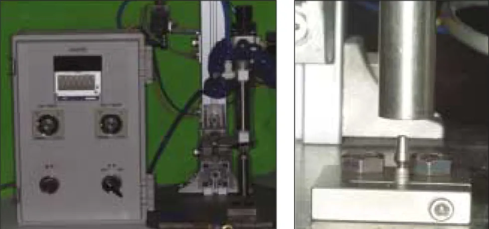
2) Loading application instrument
It was designed to tap with load of 20 kg vertically until no more sinking was occurred (Fig. 2).
2. Methods
1) Connecting abutment to the implant fixture
The abutment was slightly attached to the fixture with no pres- sure and this state of length was treated as a reference length of abutment-fixture (Fig. 3).
2) Loading conditions
Loads in the clinical order of connecting locking taper con- nection type abutment to the fixture were applied. First, the abut-
ment was connected to the fixture with finger force (Fig. 3). Then it was tapped with a mallet for 3 times (Fig. 4) and loads of 20 kg corresponding to masticatory force were applied successively.
A jig, fitting into the fixture, was made to avoid any move- ment of the fixture (Fig. 5).
In order, a finger force, 3 times of malleting force, and ver- tical load of 20 kg were added to every of 10 connected with fixtures abutment. Loads of 20 kg were added until there was no more sinking of the abutment.
3) Measuring the amount of sinking
0.01 mm unit Absolute Digimatic Caliper�(Mitutoyo, Kawasaki, Japan) was used to measure total length of abutment- fixture (Fig. 6). The abutment state, slightly connected to the fixture without pressure was considered as a reference length, and every new abutment length was measured after each load’s step was added. The amount of abutment sinking (mm) was gained by subtracting the length of abutment-fix- ture under each loading condition from reference length.
4) Statistical Analysis
SPSS 16.0 program for Windows was used to analyze statistical significance of differences between loading groups.
Also Oneway ANOVA on Ranks was conducted to see the differences between two groups fell apart.
Fig. 1.Fixture and abutment used for this study. Fig. 2.Loading application instrument.
Fig. 3.Application of finger force. Fig. 4.Tapping with a mallet. Fig. 5.Jig for implant fixation.
Fig. 6. Absolute Digimatic Caliper� (Mitutoyo, Kawasaki, Japan) for mea- surement of implant length.
Fig. 7.Change in length of abutment-fixture.
Fig. 8.Statistical significant difference between the amount of abutment sinking under each loading condition.
Table I.Amount of abutment sinking under loading application
(unit : mm) Sample No.
1 2 3 4 5 6 7 8 9 10 MeanSD
Loading condition
Load 1 0.08 0.09 0.1 0.06 0.09 0.05 0.02 0.1 0.03 0.08 0.07 0.03
Load 2 0.19 0.24 0.25 0.19 0.21 0.16 0.18 0.29 0.16 0.26 0.21 0.04
Load 3 0.36 0.38 0.34 0.26 0.35 0.23 0.23 0.38 0.24 0.32 0.31 0.06
Load 4 0.56 0.43 0.52 0.35 0.48 0.28 0.38 0.46 0.35 0.46 0.43 0.09
Load 5 0.58 0.46 0.52 0.40 0.48 0.29 0.38 0.49 0.35 0.46 0.44 0.09
Load 6 0.58 0.46 0.53 0.43 0.48 0.29 0.38 0.49 0.35 0.46 0.45 0.09
Load 7 0.58 0.46 0.53 0.45 0.48 0.29 0.38 0.49 0.35 0.46 0.45 0.09
Load 8 0.58 0.46 0.53 0.47 0.48 0.29 0.38 0.49 0.35 0.46 0.45 0.09
Load 1: Finger force 1 time application.
Load 2: Finger force 1 time and malleting force 3 times application.
Load 3: Finger force 1 time and malleting force 3 times and 20 kg 1 time application.
Load 4: Finger force 1 time and malleting force 3 times and 20 kg 5 times application.
Load 5: Finger force 1 time and malleting force 3 times and 20 kg 6 times application.
Load 6: Finger force 1 time and malleting force 3 times and 20 kg 7 times application.
Load 7: Finger force 1 time and malleting force 3 times and 20 kg 8 times application.
Load 8: Finger force 1 time and malleting force 3 times and 20 kg 9 times application.
RESULTS
1. Amount of abutment sinking under loading condition A finger force, 3 times of malleting force, and load of 20 kg were added in order and the amount of sinking was obtained by measuring length of abutment-fixture with Absolute Digimatic Caliper�(Mitutoyo, Kawasaki, Japan) (Fig. 7, Table I).
As seen above, abutment kept sinking as loads were added.
After 5 - 7 times of load of 20 kg, sinking stopped at 0.45 ± 0.09 mm, except for sample 4. It took 9 times of load of 20 kg to stop sinking.
2. Statistical analysis (Fig. 8)
In Oneway ANOVA on Ranks, the amount of abutment sinking under Load 1 showed statistically significant difference with that of Load 4 and above (Tukey Test, P < .05).
DISCUSSION
In this study, masticatory force was assumed as 20 kg. This value was referred to Gibbs and Mahan,9Craig,10Andersson,11,12’s study about occlusal force in natural dentition and Richter et al.13’s study about occlusal force while implant functioning.
However many studies demonstrated that direction and amount of occlusal force is not regular. It is reported the maximum vertical occlusal force that human can make is close to 800 N and lateral force to 20 N.14Also implants on pos- terior regions connected to premolars obtained 60 - 120 N of vertical loading while chewing were reported. In single pre- molar or molar, implants got maximum 120 - 150 N of verti- cal loading. Also clenching in centric occlusion caused 50 N of loading both in natural and artificial teeth were reported.13In this study, loading application instrument was manufac- tured and load of 20 kg corresponding to masticatory force was applied. Unlike in oral conditions, fixed loads were applied in a fixed direction which gave limitations for representing forces applied in oral conditions.
The magnitude of the forces made by finger pressure and mal- leting can be converted into numerical value using Basic Force Gauge�(Mecmesin, Slinfold, England).15Lee et al. figured out the mean value by measuring 20 times for each force and the measurement was carried out by one person. As a result, they got the average value of finger force 5.91 ± 0.58 kg, malleting force 3.35 ± 0.29 kg.
The amount of abutment sinking in Bicon�implant sys- tem was increasing as loads were added. After 5 - 7 times of load of 20 kg, sinking stopped at 0.45 ± 0.09 mm, except for sample 4. It took 9 times of load of 20 kg to stop sinking.
Studies were performed about abutment sinking. Lee et al.
observed the amount of abutment sinking in Alloden�implant system (Nei corp, Seoul, Korea) (one of locking taper connection type implant)15. They reported 0.51 ± 0.06 mm of sinking
when loads were applied 7 - 8 times in conventional abutment, and 0.75 ± 0.06 mm of sinking when loads were applied 10 - 13 times in For Deep Implant (FDI) abutment�. Comparing with our result, Bicon�implant system had less amount of sinking and less number of times needed to stop sinking than Alloden� implant system. Bruno Dailey et al. observed a continuous dis- placement of BiAbutment�(Astra Tech, Molndal, Sweden) of tapered cone screw internal connection type into implants or into replicas for torque between 0 and 45 Ncm.16There was a continous axial displacement of abutment and application of torque above the level recommended by the manufacturer increased the differences in displacement between the two groups. Comparing with our result, Bicon�implant system had more amount of sinking.
Consequently, locking taper type implant can cause occlusal discrepancy resulting from abutment sinking due to mastication.
Thus when using locking taper connection type implant like Bicon�implant system, following methods can be thought to prevent occlusal change caused by abutment sinking due to mas- tication. In laboratory, abutment should be tapped suffi- ciently in advance of making prosthesis. In clinic, dentist performs occlusal adjustment to some degree and finish com- plete occlusal adjustment after making sure the patients mas- ticate enough for period of time. In clinic, after connecting abut- ment, patients should use temporary crown for enough peri- od of time and then impression for abutment should be tak- en. Also checking amount of sinking through periodic follow- up is recommended. From statistical analysis, the amount of abutment sinking under Load 1 had statistical difference with that of Load 4 above. Thus, the length under finger force shows statistical difference with that of 3 times of malleting force and 5 times of load of 20 kg corresponding to masticatory force.
Therefore, it has clinical implication that connecting abut- ment with malleting force and applying 5 or more times of mas- ticatory force.
Therefore, when locking taper connection type implant is used, masticatory force of 5 or more times for precise abutment loca- tion and follow-up check for correcting occlusal discrepancy are recommended.
CONCLUSION
In this study, we used Bicon�Implant System (Bicon Inc, Boston, USA) to recognize the effect of abutment sinking on occlusion with Locking taper connection type implant, also some loads on abutments connected to the fixture were applied and the amount of sinking of implant was measured. Then adap- tivety of connection of abutment-fixture was observed through field emission scanning electron microscopy.
The results were as follows:
1. The amount of abutment sinking in Bicon�Implant System increased as loads were added.
2. When loads were applied more than 5 - 7 times, sinking stopped at 0.45 ± 0.09 mm.
In conclusion, locking taper connection type implant showed generally favorable fitness to masticatory force. However the amount of abutment sinking increased with adding loads.
Therefore when locking taper connection type implant such as Bicon�implant system is used, enough load strength is rec- ommended for precise abutment location.
REFERENCES
1. Binon PP. Implants and components: entering the new millennium.
Int J Oral Maxillofac Implants 2000;15:76-94.
2. Goodacre CJ, Kan JY, Rungcharassaeng K. Clinical complications of osseointegrated implants. J Prosthet Dent 1999;81:537-52.
3. Schwarz MS. Mechanical complications of dental implants. Clin Oral Implants Res 2000;11:156-8.
4. Jemt T, Laney WR, Harris D, Henry PJ, Krogh PH Jr, Polizzi G, Zarb GA, Herrmann I. Osseointegrated implants for single tooth replacement: a 1-year report from a multicenter prospec- tive study. Int J Oral Maxillofac Implants 1991;6:29-36.
5. Taylor TD. Prosthodontic problems and limitations associated with osseointegration. J Prosthet Dent 1998;79:74-8.
6. Albrektsson T. A multicenter report on osseointegrated oral
implants. J Prosthet Dent 1988;60:75-84.
7. Keating K. Connecting abutments to Dental implants “An Engineers perspective”. Irish Dentist 2001;43-6.
8. Chapman RJ, Grippo W. The locking taper attachment for implant abutments: use and reliability. Implant Dent 1996;5:257-61.
9. Gibbs CH, Mahan PE, Lundeen HC, Brehnan K, Walsh EK, Holbrook WB. Occlusal forces during chewing and swallowing as measured by sound transmission. J Prosthet Dent 1981;46:443-9.
10. Robert G. Craig. Restorative Dental Materials, 6th ed: C.V.
Mosby Co, 1980:60-2.
11. Anderson DJ. Measurement of stress in mastication. I. J Dent Res 1956;35:664-70.
12. Anderson DJ. Measurement of stress in mastication. II. J Dent Res 1956;35:671-3.
13. Richter EJ. In vivo vertical forces on implants. Int J Oral Maxillofac Implants 1995;10:99-108.
14. Van Eijden TM. Three dimensional analysis of human bite- force magnitude and moment. Arch Oral Biol 1991;36:535-9.
15. Lee HL, Kim HJ, Son MK, Chung CH. Abutment sinking and fit- ness of conical internal connection implant system according to loading condition. J Korean Acad Stomatognathic Funct Occlusion 2008;24:77-89.
16. Dailey B, Jordan L, Blind O, Tavernier B. Axial displacement of abutments into implants and implant replicas, with the tapered cone-screw internal connection, as a function of tightening torque. Int J Oral Maxillofac Implants 2009;24:251-6.