Introduction
Measured resection techniques, gap techniques, and com- binations of both are used in total knee arthroplasty (TKA) to achieve rectangular extension and flexion gaps perpendicular to the mechanical axis of the tibia1-6). Measured resection techniques in which the femoral component is placed 3o externally rotated to the posterior condylar line during TKA for medial osteoarthritis can result in lateral instability and excessive medial release. Gap techniques in which soft tissue release is performed with reference to the resected tibial surface can cause anterior notching or overhang of the femoral component and tibiofemoral instability because the femoral component is inserted internally rotated.
Malrotation of the femoral component has been associated with knee instability, knee pain, asymmetric polyethylene wear, and abnormal knee motion7-9). The purpose of this study was to
Rotational Alignment of Femoral Component for Minimal Medial Collateral Ligament Release in Total Knee Arthroplasty
Je Gyun Chon, MD, Doo Hoon Sun, MD, Jae Yong Jung, MD, Tae In Kim, MD and Seong Won Jang, MD
Department of Orthopedic Surgery, Sun General Hospital, Daejeon, Korea
This is an Open Access article distributed under the terms of the Creative Commons Attribution Non-Commercial License (http://creativecommons.org/licenses/by-nc/3.0/) which permits unrestricted non-commercial use, distribution, and reproduction in any medium, provided the original work is properly cited.
Copyright © 2011. THE KOREAN KNEE SOCIETY
www.jksrr.org
pISSN 2234-0726 · eISSN 2234-2451
Knee Surgery & Related Research
Purpose: We attempted to determine the degree of rotation of the femoral component to achieve an ideal rectangular flexion gap with minimal medial collateral ligament (MCL) release using a modified measured technique.
Materials and Methods: Group I consisted of 60 osteoarthritis patients (72 cases) who underwent total knee arthroplasty (TKA) with minimal MCL release and Group II consisted of 48 patients without osteoarthritis (61 cases). We performed computed tomography (CT) scanning of the knee with 90 degree flexion in all of the patients and analyzed the angles between the distal femur landmarks and the tibial mechanical axis using a Picture Archiving Communication system. External rotation of the femoral component from the Whiteside line and posterior condylar line was measured in group I who underwent TKA with minimum MCL release. The variance in the mediolateral flexion gap according to the degree of rotation was also measured using an Auto-Computer Aided Design program.
Results: The CT scans showed that the Whiteside line, posterior condylar line, and transepicondylar line was more internally rotated on average from the longitudinal axis of tibia by 4.12o, 5.54o, and 4.64o, respectively, in group I compared to group II. In group I, the femoral component was inserted with an average external rotation of 5.6o from the posterior condylar line and with an average external rotation of 2.0o from the Whiteside line with minimal MCL release. From the measurements of the femoral component size and the variance in the degree of rotation using an Auto-CAD program, it was found that the change in the mediolateral flexion gap was greater when the rotation angle was greater and it was greater when the size of femoral component was larger at the same rotation angle.
Conclusions: The average rotation angle of the femoral component to achieve an ideal rectangular flexion gap with minimal MCL release in TKA was an external rotation of 5.6o from the posterior condylar line and an external rotation of 2.0o from the Whiteside line. We concluded that when a femoral component is small in size, greater than average external rotation needs to be applied and when a femoral component is large in size, less than average external rotation needs to be applied.
Key words: Knee, Total knee arthroplasty, Femur, Rotation alignment.
Received April 23, 2011; Revised (1st) May 7, 2011; (2nd) July 3, 2011;
Accepted July 12, 2011.
Correspondence to: Doo Hoon Sun, MD.
Joint Center, Sun General Hospital,
10-7 Mok-dong, Jung-gu, Daejeon 301-725, Korea.
Tel: +82-42-220-8220, Fax: +82-42-254-4955 Email: [email protected]
*We presented this paper at the autumn conference of the Korean Orthopaedic Association in 2010.
153
determine the optimal femoral component rotation to achieve an ideal rectangular flexion gap with a modified measured resection technique and minimal medial collateral ligament (MCL) release.
Materials and Methods
Sixty patients (72 cases) who underwent TKA with minimal MCL release for medial osteoarthritis at our institution between June 2009 and February 2010 were enrolled into group I. Forty- eight patients without osteoarthritis were enrolled into group II.
In group I, the mean age of the patients was 68.1 years (range, 52 to 93 years) and the exclusion criteria were severe defects including femoral condylar hypoplasia and osteonecrosis. In group II, the mean age of the patients was 53.8 years (range, 22 to 71 years). In group I, 12, 33, and 27 cases were ≤60, 61-70, and
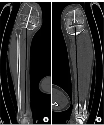
≥71 years of age, respectively. In group II, 21, 20, and 20 cases were ≤50, 51-60, and ≥60 years of age, respectively. There were 8 males and 52 females in group I and 16 males and 32 females in group II. Preoperatively, a computed tomography (CT) scan was carried out with the knee flexed to 90o in all of the patients and measurements were performed using a Picture Archiving Communication (PAC) system. During the CT scan, a plaster cast was used to keep the 90 degree knee flexion position and the knee joint was maintained in the gravitational weight of the lower limb. The angles created by the mechanical axis of tibia, Whiteside line, posterior condylar line, and transepicondylar line were measured on the CT images and compared (Fig. 1).
In group I, TKA was performed with minimal MCL release alone and external rotation angles of the femoral component relative to the posterior condylar line and Whiteside line were measured after distal femur resection (Fig. 2). In the minimal MCL release, the anterior portion of the superficial medial collateral ligament, some deep medial collateral ligaments, and posteromedial capsule were included, not the posterior portion of Fig. 1. (A) Mechanical axis of tibia, White side line, trans epicondylar
line, and posterior condylar line in the osteoarthritis group. (B) Mecha- nical axis of tibia, White side line, transepicondylar line, posterior condylar line in the normal group.
Fig. 2. (A) Femur cutting with 6.0o external rotation than posterior condylar line. (B) Femur cutting with 2.0o external rotation than Whiteside line.
the superficial medial collateral ligament, the semimembranosus tendon, and the pes anserius tendon.
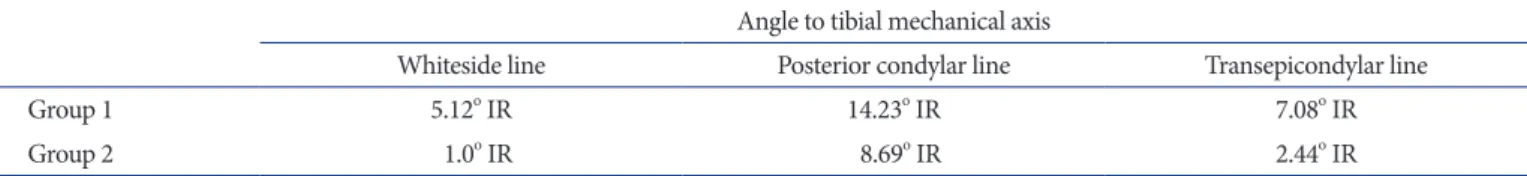
The flexion gap was set as 20 mm when a mid-sized tibial component (67 mm), one of the most common Biomet Vanguard knee replacement systems, was used (Figs. 3, 4). For different size femoral components, 55 mm (A), 60 mm (B), 65 mm (C), and 70 mm (D), changes in the mediolateral flexion gap with external rotation of 0o, 3o, 5o, and 6o were measured using an auto-CAD program (Fig. 5). The anteroposterior (AP) bone cutting size of the femur was measured for each prosthesis: A, 38.100 mm; B, 42.113 mm; C, 46.609 mm; and D, 51.029 mm. The flexion gap of 20 mm was calculated by adding the posterior thickness of the femoral prosthesis (9 mm), polyethylene thickness (7 mm), and tibial prosthesis thickness (4 mm).
Results
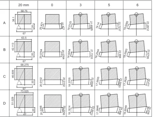
In group I, relative to the tibial mechanical axis, the Whiteside line, posterior condylar line, and transepicondylar line were internally rotated by a mean of 5.12o, 14.23o, and 7.08o, respectively. In group II, relative to the tibial mechanical axis, the Whiteside line, posterior condylar line, and transepicondylar line were internally rotated by a mean of 1.0o, 8.69o, 2.44o, respectively (Table 1, Fig. 1).
Statistically significant differences were found between group I and group II regarding the mean angles between the tibial
mechanical axis and the Whiteside line, the posterior condylar line, and the transepicondylar line (p=0.000). In each group, no statistically significant differences were found regarding the age.
In group I, a modified measured technique was used with minimized MCL release and external rotation of the femoral component relative to the posterior condylar line and Whiteside line was measured, which was a mean of 5.6o (range, 3o to 8o) and 2.0o (range, 1o to 3o), respectively (Fig. 2).
On the Vanguard femoral component analysis using an Auto- CAD program, when the 55 mm femoral component (A) was not rotated, the medial flexion gap and external flexion gap were the same, 20.421 mm. When the component was externally rotated by 3o, the medial flexion gap increased to 21.6985 mm and the lateral flexion gap decreased to 19.5125 mm. When the component was externally rotated by 5o, the medial flexion gap increased to 22.7237 mm and the lateral flexion gap decreased to 19.14 mm. The changes in the flexion gap according to the degree
Fig. 3. Vanguard’s femoral component anteroposterior (AP) & Lateral views. (A) Femoral M/L size (55, 60, 65, 70 mm). (B) Femoral AP size (bone cutting). (C) Femoral component AP size .
Fig. 4. Model of Auto-CAD. a: femoral component M/L size, b: femoral bone cutting anteroposterior size, c: tibial component M/L size (67 mm), d: femoral component thickness+bearing thickness+tibial component thickness (20 mm), e: medial flexion gap. f: lateral flexion gap.
Table 1. Angles between Land Marks and Tibial Mechanical Axis in Computed Tomography Study Angle to tibial mechanical axis
Whiteside line Posterior condylar line Transepicondylar line
Group 1 5.12o IR 14.23o IR 7.08o IR
Group 2 1.0o IR 8.69o IR 2.44o IR
IR: internal rotation.
of external rotation of the femoral component are described in Fig. 5.
When the femoral component was not externally rotated, the medial flexion gap and the lateral gap were the same: 20.421 mm for A, 20.0764 mm for B, 20.0102 mm for C, and 20.2256 mm for D. The changes in the medial flexion gap and the lateral flexion gap according to the degree of external rotation of A were as follows: 3o, +1.2775 mm and -0.9085 mm, respectively; 5o, +2.3027 mm and -1.281 mm, respectively; and 6o, +2.8602 mm and -1.3925 mm, respectively. The changes in the medial flexion gap and the lateral flexion gap according to the degree of external rotation of B were as follows: 3o, +1.6469 mm and -1.251 mm, respectively; 5o, +2.9216 mm and -1.8220 mm, respectively; and 6o, +3.6031 mm and -2.0201 mm, respectively. The changes in the medial flexion gap and the lateral flexion gap according to the degree of external rotation of C were as follows: 3o, +2.0494 mm
and -1.6397 mm, respectively; 5o, +3.5891 mm and -2.4447 mm, respectively; and 6o, +4.4008 mm and -2.7474 mm, respectively.
The changes in the medial flexion gap and the lateral flexion gap according to the degree of external rotation of D were as follows:
3o, +2.4656 mm and -2.0642mm, respectively; 5o, +4.2704 mm and -3.1410 mm, respectively; and 6o, +5.2104 mm and -3.5707 mm, respectively (Table 2, Fig. 5).
The medial flexion gap change + the lateral flexion gap change when the component was externally rotated by 3o was: A, 2.186 mm; B, 2.8979 mm; C, 3.6891 mm; and D, 4.5298 mm. The value when the component was rotated by 5o was: A, 3.5837 mm; B, Table 2. Medial Flexion Distance Change+Lateral Flexion Distance
Change
Size 0o 3o ER 5o ER 6o ER
55 mm (A) 0 2.1860 3.5837 4.2527
60 mm (B) 0 2.8979 4.7436 5.6232
65 mm (C) 0 3.6891 6.0338 7.1482
70 mm (D) 0 4.5298 7.4114 8.7811
ER: external rotation.
Fig. 5. Medial & lateral flexion distance change after bone cutting and femoral component insertion with external rotation of 3o and 5o and 6o for each femoral M/L size -55 mm (A), 60 mm (B), 65 mm (C), 70 mm (D).
Fig. 6. The sum of mediolateral flexion distance changes.
4.7436 mm; C, 6.0338 mm; and D, 7.4114 mm. The value when the component was rotated by 6o was: A, 4.2527 mm; B, 5.6232 mm;
C, 7.1482 mm; and D, 8.7811 mm. Therefore , the mediolateral flexion gap change were correlated positively to the component size in same degree of external rotation (Table 2, Fig. 6).
Discussion
Rotation alignment of the femoral component in TKA is essential for the stability of the tibiofemoral joint. Insufficient external rotation of the femoral component has been associated with subluxation or dislocation of the patellofemoral joint and loosening and wear of the patellar component tibial components6,10). Excessive MCL release for flexion contracture of the tibiofemoral joint compromises stability of the knee after TKA. To prevent ligamentous instability caused by over-release, Clayton et al.3) recommended staged release and Dixon et al.11) reported that proper release could be obtained with use of shift
& resection technique. However, determining a proper release is challenging because when the semimembranosus and pes anserinus tendons are over-released, the flexion gap becomes larger than the extension gap3,12). Although the transepicondylar axis has been known as a reliable reference to determine the rotational alignment of the femoral component in TKA13), it is covered by soft tissue making intraoperative measurements difficult. The Whiteside line was externally rotated relative to the posterior condylar line In osteoarthritis patients by 3.89o in the study of Whiteside and Arima14) and by 3.08o in the study of Poilvache et al.10). In our study, the value was 9.11o of external rotation in patients with osteoarthritis and 7.69o of external rotation in patients without osteoarthritis (Table 1). This can be interpreted that the distal femur was more internally rotated by 1.42o in the patients with osteoarthritis. However, relative to the tibial axis, the Whiteside line was internally rotated by 1.0o in patients without osteoarthritis and by 5.12o in osteoarthritis patients. Accordingly, we think that the posterior femur should be cut 2o more externally rotated than perpendicular to the Whiteside line to obtain a proper flexion gap as opposed to perpendicular to the Whiteside line suggested by Whiteside and Arima. Schnurr et al.15) reported that the rotational alignment of the femoral component should not be solely based on the posterior condylar line because it is unreliable in achieving a proper flexion gap. In this study, we used the posterior condylar line and Whiteside line to measure the mean external rotation.
The medial flexion gap change + the lateral flexion gap change was 4.2527 mm for A (55 mm) when inserted with an external
rotation of 6o, but the value was 4.5298 mm for D (70 mm) when inserted with an external rotation of 3o as described in Table 2. The change in the mediolateral flexion gap was found to be correlated with the femoral component size. Therefore, it is our understanding that when the femoral epicondyle is small, the external rotational angle should be larger than the average and when the femoral condyle is large, the angle should be smaller than the average to obtain a proper flexion gap.
Conclusions
This study showed that the mean external rotation of the femoral component to achieve an ideal rectangular flexion gap with minimal MCL release in TKA for medial osteoarthritis is 5.6o from the posterior condylar line and 2.0o from the Whiteside line. On the analysis of the relationship between the femoral component size and the external rotation using an Auto-CAD program, there were positive correlations between the external rotation angle and the mediolateral flexion gap change and between the femoral component size and the mediolateral flexion gap change at the same rotation angle. We recommend that greater than average external rotation should be applied for small-sized femoral components and less than average external rotation should be applied for large-sized femoral components to achieve an ideal flexion gap.
References
1. Insall JN, Binazzi R, Soudry M, Mestriner LA. Total knee arthroplasty. Clin Orthop Relat Res. 1985;(192):13-22.
2. Bottros J, Gad B, Krebs V, Barsoum WK. Gap balancing in total knee arthroplasty. J Arthroplasty. 2006;21:11-5.
3. Clayton ML, Thompson TR, Mack RP. Correction of alignment deformities during total knee arthroplasties:
staged soft-tissue releases. Clin Orthop Relat Res.
1986;(202):117-24.
4. Scott RD. Primary total knee arthroplasty surgical technique.
In: Scott RD, ed. Total knee arthroplasty. Philadelphia:
Saunders; 2006. p20-38.
5. Whiteside LA, Saeki K, Mihalko WM. Functional medical ligament balancing in total knee arthroplasty. Clin Orthop Relat Res. 2000;(380):45-57.
6. Insall JN. Technique of total knee replacement. Instr Course Lect. 1981;30:324-9.
7. Fehring TK, Valadie AL. Knee instability after total knee arthroplasty. Clin Orthop Relat Res. 1994;(299):157-62.
8. Krackow KA, Mihalko WM. The effect of medial release on flexion and extension gaps in cadaveric knees: implications for soft-tissue balancing in total knee arthroplasty. Am J Knee Surg. 1999;12:222-8.
9. Saeki K, Mihalko WM, Patel V, Conway J, Naito M, Thrum H, Vandenneuker H, Whiteside LA. Stability after medial collateral ligament release in total knee arthroplasty. Clin Orthop Relat Res. 2001;(392):184-9.
10. Poilvache PL, Insall JN, Scuderi GR, Font-Rodriguez DE.
Rotational landmarks and sizing of the distal femur in total knee arthroplasty. Clin Orthop Relat Res. 1996;(331):35-46.
11. Dixon MC, Parsch D, Brown RR, Scott RD. The correction of severe varus deformity in total knee arthroplasty by tibial component downsizing and resection of uncapped proximal medial bone. J Arthroplasty. 2004;19:19-22.
12. Insall JN, Easley ME. Surgical techniques and instrumen- tationin total knee arthroplasty. In: Insall JN, Scott WN, eds. Surgery of the knee. 3rd ed. New York; Churchill Livingstone; 2001. p1553-620.
13. Berger RA, Rubash HE, Seel MJ, Thompson WH, Crossett LS. Determining the rotational alignment of the femoral component in total knee arthroplasty using the epicondylar axis. Clin Orthop Relat Res. 1993;(286):40-7.
14. Whiteside LA, Arima J. The anteroposterior axis for femoral rotational alignment in valgus total knee arthroplasty. Clin Orthop Relat Res. 1995;(321):168-72.
15. Schnurr C, Nessler J, Konig DP. Is referencing the posterior condyles sufficient to achieve a rectangular flexion gap in total knee arthroplasty? Int Orthop. 2009;33:1561-5.