Vol. 17, No. 1 pp. 331-339, 2016
A Study on Development of a Smart Wellness Robot Platform
Byoungsu Lee
1, Seungwoo Kim
1*1Electronic information engineering, Soonchunhyang Univ
스마트 웰니스 로봇 플랫폼 개발에 관한 연구
이병수1, 김승우1*
1순천향대학교 전자정보공학과
Abstract This paper developed a home wellness robot platform to perform the roles in basic health care and life care in an aging society. A robotic platform and a sensory platform were implemented for an indoor wellness service.
In the robotic platform, the precise mobility and the dexterous manipulation are not only developed in a symbiotic service-robot, but they also ensure the robot architecture of human friendliness. The mobile robot was made in the agile system, which consists of Omni-wheels. The manipulator was made in the anthropomorphic system to carry out dexterous handwork. In the sensing platform, RF tags and stereo camera were used for self and target localization.
They were processed independently and cooperatively for accurate position and posture. The wellness robot platform was integrated in a real-time system. Finally, its good performance was confirmed through live indoor tests for health and life care.
요 약 본 논문에서는 노령화 사회에서 노인들의 기본 건강과 생활을 케어 할 수 있는 홈 웰니스 로봇 플랫폼을 개발한다.
실내 환경에서 웰니스 서비스에 초점을 맞추어 로봇 및 센서 플랫폼을 구현한다. 로봇플랫폼에서는 정밀제어 이동기능과 정교한 로봇 팔 및 핸드를 개발하고 인간친화형 로봇구조로 설계되어진다. 이동로봇은 옴니휠 기반의 쾌속 시스템으로 제어 된다. 로봇팔은 섬세한 조작기능을 수행할 수 있도록 인간의 팔과 유사한 구조로 구현한다. 센서 플랫폼에서는 RF태그와 스테레오 카메라를 활용하여 로봇자신과 대상물체의 위치 인식시스템을 구축한다. 정확한 위치와 자세 인식을 위하여 센서 융합 알고리즘이 제안된다. 끝으로 웰니스 로봇 플랫폼의 좋은 성능들이 실시간 시험 구동을 통하여 확인되어 진다.
Keywords : Home Wellness Robot Platform, Omni-Wheeled Mobile Robot, 6 DOF Manipulator, RFID Sensor, Stereo Vision
This research was supported by Basic Science Research Program through the National Research Foundation of Korea (NRF) funded by the Ministry of Education (NRF-2011-0009541).
*Corresponding Author : Seungwoo Kim(Soonchunhyang University) Tel: +82-41-530-1369 email: [email protected]
Received September 16, 2015 Accepted January 5, 2016
Revised (1st November 30, 2015, 2nd December 8, 2015) Published January 31, 2016
1. Introduction
1Service robotics is expected to play an actual and important role in complex domestic environments. A great deal of concern of service robot is given in more elderly society. It is very important to develop the service robot on a smart wellness platform, to perform
roles in both health care and life care in an aging house. A home wellness robot is defined in the area of intersection between medical and housemaid types, able to carry out combined roles in health and life care.
To really do that, the most optimal geometry structure of a two-armed humanoid robot, with mounted manipulators on a wheeled mobile robot, should be
designed[1]. A symbiotic service robot must not only have skills of precise mobility and dexterous manipulation, but also functions of both self and target localization. It have to be developed for the logics related to remote medical diagnosis, nursing, and life care. Omni-wheeled mobility and an anthropomorphic 6 DOF(degree of freedom) manipulator are developed for a robotic platform in this paper. A home service robot needs not only precise control but also optimization of kinematic geometry structure, because it operates in close proximity to humans[2]. Optimal design is needed in width and depth of its body, which is to ensure a good workspace of the home service robot. There are so many obstacles in a typical house interior. It should be equipped with the minimum number of mechanical and electronic components on its base frame. The other optimization is also needed in the implementation of the robotic waist and arm. That makes them operate like human. But the human waist can, as one likes, move the body’s center of gravity when it operates. The long robot arms impose a big burden on the shoulders. It makes the robot control difficult. So, A new kinematic geometry structure is proposed to serve wellness in door.
The wellness robot needs the function of agile navigation and a novel manipulation system for household chores. The autonomous navigation system has to be controlled for the full scanning of the living area and for the precise tracking of the desired path. A Swedish OWMR (Omni-wheeled mobile robot), with a proposal of a new control algorithm, is developed as a holonomic system in this paper. A wellness robot needs a dexterous manipulation capability. Manipulators are divided into general and special purpose. Both of them have such design parameters as workspace, range of joint angle, joint torque, link length and mass. Most special-purpose arms for service robots are developed as built-in types. These built-in arms are necessarily finitely implemented on link length and joint torque, and are always compromised between these two characteristics. They cause the workspace of the arms
to be smaller. Nevertheless, it is essential to provide enough workspace to perform home service tasks. So, this paper proposes a novel design strategy of the built-in type arms. A new type of joint, installed on the neck, is used to provide adequate horizontal workspace on the working floor.
The self and target localization systems are developed for a sensory platform. This paper technically implements the sensor network system for a home wellness robot. Radio frequency (RF) tags are set in door[3]. The absolute coordinate information is acquired through an RF reader. The coordinate information is fused with that from the stereo camera of the home wellness robot. The self-localization of the wellness robot is precisely derived by this collaboration. Depth information to an object is extracted for the 3D positioning. Then the angle difference of the robot and the object is calculated by a warped angle based on the center of the image.
Finally, we implement the feedback control of the wellness robot with the information from the stereo camera and the RFID sensor. Good performance of the robotic and sensory platforms is confirmed through live tests with the home wellness robot in a smart environment.
2. The Robotic Platform
2.1 Robotic Geometry Structure
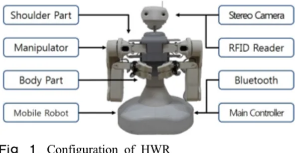
A HWR (home wellness robot) needs not only optimization of kinematic geometry structure but also precise control, because it is in close proximity to humans. HWR, which performs health and life care in home, is designed much more optimally than other service robots. The home service robot for wellness care is designed with consideration of its optimum height, width and depth. We also have to optimize the variation of its centroid point and the kinematics of its waist and arm[4]. HWR is divided into four key parts:
shoulder, manipulation, body, and mobile base frame.
Its appearance is shown in Fig. 1.
Fig. 1. Configuration of HWR
A home service robot have to be able to efficiently serve in the standing position, such as at the council board, the dining table and the sink. The height of the dining table and the sink, which are in everyday use in most homes, is generally about 800–850 mm. Thus, much taller robot than any other ones is implemented in Fig. 1 in this paper. The other optimization is needed on the design of the waist and arms of the HWR. The robotic waist is developed to freely move the center of gravity when it operates, The long arms impose a big burden on the shoulders. Therefore, the most optimal kinematic geometry structure is implemented to solve these problems in this paper.
Fig. 2. Optimal mechanism of built-in manipulators
2.2 6 DOF Mainipulation
We propose a novel design strategy for the built-in type arms. The joints installed on the neck are used to get adequate horizontal workspace on the working floor. The lift-type joint installed on the waist is used to get adequate vertical workspace on the working floor. Its mechanism is explained in Fig. 2.
The built-in type hands of a home service robot must be mechanically designed in a task-oriented system. Task-based implementation of hands cannot help making the DOF high. There is great difficulty in installing numerous actuators and coupling devices in the restricted space[5].
This paper proposes an optimal design method to efficiency satisfy both a minimum DOF and maximum workspace. The hand consists of two fingers and a thumb, where the finger mechanism is well designed to stably grasp typical objects in a human’s daily activities, such as spherical and cylinder-shaped objects. The restriction of possible motions and the limitation in grasping objects arising from the reduction of the DOF can be overcome by incorporating a cooperative technique between the two hands and a tasks-extracted motion profile in the design process.
Fig. 3. Optimal mechanism of HWR hands
The hand mechanism of the HWR uses a four-bar-link finger and a Dustin type finger. The four-bar-link method is explained in Fig. 3. Joint points C, D and E can be moved on the base of actuating point A and fixed point B. As a result, the developed hand can resemble not only the shape of a human
hand, but also its motion in a compact and efficient manner. The specifications of the developed built-in manipulator are set out in Table 1.
Table 1. Specification of Manipulator
Total Length 874mm Motor(1)s EX-106(106kgf) Total Width 590mm Motor(2,3)e EX-64(64kgf.cm) Arm Weight 2.11Kg Motor(4,56)h EX-28(64kgf.cm) Actuators 16 units Material Apex PA2, AL 707
2.3 Omni-wheeled Mobile Robot
This section considers an accurate trajectory control method for a three-wheeled omni-directional mobile robot using a fuzzy azimuth estimator. The OWMR of this paper has three omni-directional wheels, separated by 120 degrees. Each wheel is driven by a DC motor installed with an optical shaft encoder. A gyro sensor is used for the perception of azimuth. The control structure using a fuzzy azimuth estimator is shown in Fig. 4.
It is controlled by independent PID law for each motor to follow the speed command from inverse kinematics without considering the coupled nonlinear dynamics explicitly in the controller design. The state and output equations are described in the absolute coordinate system.[6] It should be noted, however, that the control input is the quantity in the relative coordinate system.
Therefore, the control input in the absolute coordinate system must be transformed into the control input for each assembly, i.e., the signal expressed in the relative coordinate system, if the control input is designed in the absolute coordinate system. Then, the transformation for each input can be derived from kinematics, as follows.
(1)
A trajectory controller for an omni-directional mobile robot needs precise sensing data of its azimuth and exact estimation value of a reference azimuth. It has the imprecision and uncertainty inherent to perception sensors for azimuth. The imprecision is made by sensor noise and aliasing. The uncertainty consists of disturbance and slip of the mobile robot.
Fig. 4. Tracking control structure
As we can see in Fig. 4, they are solved by using fuzzy logic inference. That can be straightforwardly used to perform control of the mobile robot by means of the fuzzy behavior-based scheme already existing in the literature. The new enhancement azimuth is derived as fuzzy inference system.
Fig. 5. Fuzzy Inference System for Azimuth
As we can see in Fig. 5, is the k-th desired azimuth angle computed from trajectory planning,
is the k-th output of the gyro sensor and
is k-th output of encoder. and
is the error between desired azimuth angle and gyro/encoder output value. is the new value of the (k+1)-th azimuth.
Mamdani’s inference engine is used in this fuzzy controller. The input signal is the change rate of the
error between the desired azimuth and the gyro/encoder sensors. Center of gravity(COG) is used for defuzzification. The fuzzy rule base of linguistic variables is given in Table 2.
Table 2. Fuzzy Rule Base Change Rate
of Error
NE ZE PE
.
NE PB PS NS
ZE PS ZE NS
PE PS NS NB
3. The Sensory Platform
3.1 RFID
In the sensory platform, an RF tag and a stereo camera are used for self and target localization. They are independently and cooperatively processed for optimal positioning and posture. The location of the RF tag is estimated by using angle instead of distance in this paper[7,8,9]. We need to know a side length and an edge angle of a triangle, which is derived by the data from RF tags, to obtain the distance of an object.[10] Because the sum of a triangle is 180 degrees, an unknown angle and the lengths of the other two sides can be calculated from two known angles.
Using the Pythagorean theorem, the coordinates of a point can be determined.
Fig. 6. Triangulation Algorithm
We can know the distance from each tag and determine the position by using triangulation, if a phase angle is given. The basic method of triangulation makes two angles and the length of the baseline AB measurable. are outputs from the RFID sensors, which can be measured. At this time, the position of C
is obtained from a RC. The included in edge C is calculated by the simple equation [180- ]. The lengths of AC and BC can be calculated by using the following equation by the trigonometric sine laws.
∙
∙
(2)
∙ ∙ (3) The distance is obtained from Eq. (4) and the coordinates are converted.
(4)
3.2 Stereo Vision
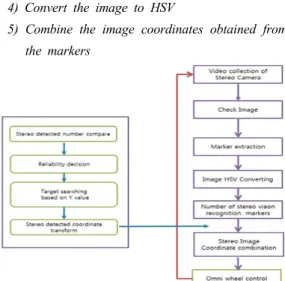
We need path control for the robot’s approach to an object. In this section, it is solved by using a stereo vision system. The object information gathered from RF tags is compared with markers installed in the wellness robot. If an object is recognized, its image is acquired from the vision sensor. The robot’s path and posture are determined from the angle of the image. Of course, to make the path, object recognition should be preprocessed. In this paper, we propose a marker algorithm. It is implemented by several steps.
1) Check the marker image 2) Acquire it from stereo camera 3) Compensate the color image 4) Convert the image to HSV
5) Combine the image coordinates obtained frome the markers
Fig. 7. Marker algorithm of stereo vision system
As shown in Fig. 7, the angle and orientation which is smartly acquired from markers is provided for the path of the home wellness robot
4. Experiment and Result
4.1 Experimental Setup
We develop a new service robot, a home wellness robot in this paper. Dimensions of the wellness robot are 440 x 560 x 1100 mm. The height of the lift is set to 700 mm. A wellness robot which includes all the optimal features is implemented. For convenience in experimentation, the floor of the living room is of the size, 2400 x 4800 mm. The built-in type manipulators, which are developed for the special purpose of wellness care indoors, consists of arms with three DOF each and hands with three DOF each. The robotic arm is optimally designed to satisfy both the minimum mechanical size and the maximum workspace.
Minimum mass and length are required for the built-in cooperated-arms system. Satisfying those requirements can make the workspace small. So, this paper proposes an optimal design method which meets all these requirements to a satisfactory level. A mobile robot with three omni-directional wheels is developed, for precise mobility. The DC motor, which has a torque rating of 31kg·cm, is used for driving the omni- directional wheeled mobile robot. The diameter of the omni-directional wheel is 79mm and the distance from the center point of the robot to each wheel is 198mm.
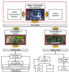
To precisely control them, this paper proposes a new architecture of the control system. Its configuration is shown in Fig. 8
To recognize the absolute 3D coordinates, RF tags are installed on the four corners of the ceiling. The distance of RF tags is minimized to avoid mutual interference, as shown in Fig. 9
Fig. 8. Control system configuration
Fig. 9. RFID sensory platform
The target localization is realized by the stereo vision system. Markers are recognized from the images and the warped angle is measured from their centers.
The wellness robot can carry out caring tasks though self and target localization using the RFID sensors and the stereo vision system.
(a) left camera (b) right camera Fig. 10. The matching algorithm of image calibration
The image calibration is shown in Figure 10(a) and 10(b). It is alternately processed on left and right ones to compensate and enhance disturbed images. The matching algorithm of two images can drive distance to the object. Finally, we acquire 3 dimensional localization information of the object.
4.2 Test and result
Fig. 11 shows that the peak tracking error (the difference between the trajectory command and the robot response) is under m, and the orientation angle tracking error is less than two degrees. It should be noted that both are achieved on the same order, with and without robot self-rotation.
Fig. 11. Position (x,y) and orientation() response
Fig. 12 is an experimental result of the fused algorithm of RFID triangulation and vision marker method. The estimated positions, SLP (self-localized point) and TLP (target-localized point), were acquired from the combination of the two methods of RFID sensors and stereo vision system. We can find out in the experiment in which the proposed algorithm is applied in real-time. The self-localization of HWR is significantly improved through the experimental result.
Fig. 12. SLP and TLP acquired by sensor fusion algorithm
The built-in type manipulator, which is developed for the special purpose of an indoor wellness robot, consists of arms with three DOF each and hands with three DOF each. The robotic arm is optimally designed to satisfy both the minimum mechanical size and the maximum workspace.
Minimum mass and length are required for the built-in manipulation system. But those requirements make the workspace smaller. We propose an optimal design method to overcome the problem by using a neck joint to move the arms horizontally forwards and backwards, and a waist joint to move them vertically up and down. The robotic hand, which has two fingers and a thumb, is also optimally designed for task-based concept in this paper.
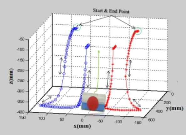
Fig. 13 shows path control of the both robot arms for wellness service. It is the task to pull up object in initial position. The manipulation experiments were performed to analyze the controllability of the two robotic arms and hands for indoor wellness service.
The manipulators, which are optimally designed, are used in the experiment. Its exact path control, which is moved on a three-dimensional coordinate system, is shown in Fig. 13.
Fig. 13. Path control of robot arms for wellness service
5. Conclusions
A home wellness robot platform, to perform a role of both health care and life care in an aging society, was perfectly developed in this paper. Especially, this paper concentrated its focus on the implementation of mobility and manipulation system. Also, the focus was given on the implementation of self and target localization system. The optimum kinematic geometry structure was proposed and its precise control was implemented for the better wellness service. A holonomic mobile robot using three omni-directional wheels and specialized anthropomorphic manipulators were developed for the robotic platform.
In the sensory platform, this paper implemented an RFID and vision sensor network system for precise self-localization of the smart home wellness robot. We could get precise information of its position and posture through the collaboration of the RFID and vision system. Finally, the good performance of the developed wellness robot platform was confirmed through live test of tasks in both health care and life care in a home for elderly people.
References
[1] Bischoff R. HERMES “A Humannoid Mobile manipulator for service Tasks.” In: Proceeding of the FSR’97 Conference on Field and Service Robots, 1997, pp508-515 [2] Connette CP, Pott A, Hägele M, Verl “A. Control of an
Pseudo-Omnidirectional, Non-Holonomic, Mobile Robot based on an ICM Representation in Spherical Coordinates.” In: Proceedings of the 47th IEEE conference on Decision and Control, 2008; pp 4976-4983.
[3] H. S. Ahn, J. Y. Lee, W.P.Yu, K.S.Han, “Indoor Localization Technique for Intelligent Robotic Space", Vol. 22, No. 2, pp48-57, 2007.4
[4] Jeon Hyeon-Sig, Woo Sung-Hyun, Lee Ho-Eung, Ryu In-seon, Yoon Sung-Kun, Park Hyun-ju, “ A Study on Algorithm for Efficient Location Tracking in Indoor Environment”, Journal of Information Technology Applications
& Management Vol. 13 No. 3 pp.59-74, 2006. 9 [5] K. Harada et al., “Dynamics and Balance of a Humanoid
Robot during Manipulation Tasks,” IEEE Trans. on Robotics, vol. 22, No. 2, 2006, pp. 568-575
DOI: http://dx.doi.org/10.1109/TRO.2006.870649 [6] Lomg XIAO, Ye YIN, WU, Jianewi WANG, “A Large –scale
RF-based indoor Localization System Using Low-complexity Gaussian Filter and Improved Bayesian ingerence”
RADIOENGINEERING, VOL. 22, NO. 1, APRIL 2013.
[7] R. Tamasaki. “TDOA Location system for IEEE 802.11b WLAN.” Proc. of IEEE, vol.1, pp. 980-684, 2001 [8] Cesare Alippi, Giovanni Vanini: A RSSI-based and
calibrated centralized localization technique for Wireless Sensor Networks, in Proceedings of Fourth IEEE International Conference on Pervasive Computing and Communications Workshops (PERCOMW’06), Pisa, Italy, March (2006), pp. 301-305
[9] Filonenko, Viacheslav; Cullen, Charlie; Carswell, James D. 2013. "Indoor Positioning for Smartphones Using Asynchronous Ultrasound Trilateration." 2, no. 3: 598-620.
[10] R. Tamasaki. “TDOA Location system for IEEE 802.11b WLAN.” Proc. of IEEE, vol.1, pp. 980-684, (2001)
Byoungsu Lee [Student member]
•Feb. 2013 : Soonchunhyang Univ., Electrical Infromation Eng., Bachelor
•Feb. 2013 ~ Feb. 2015 : Soonchunhyang Univ., Dept. of Electrical Robotics Eng., Course of MS
<Research Interests>
Robot control, Fuzzy control system, Intelligent robot, Service Robot, Mobile control
Seungwoo Kim [Regular member]
•Feb. 1987 : Yonsei Univ., Dept.
of Electronic Eng., Bachelor
•Feb. 1994 : Yonsei Univ., Dept.
of Electronic Eng., MS
•Feb. 1994 : Yonsei Univ., Dept.
of Electronic Eng., PhD
•Jan. 1998 ~ Feb. 1999 : CWRU Post-Doctoral Program in Robotics.
•Jan. 1987 ~ Aug. 1989 : Samsung Advanced Institute of Technology, Researcher
•Feb. 1994 ~ current : Soonchunhyang Univ., Dept. of Electrical Information Eng., Professor
<Research interest>
Robot control, Fuzzy control system, SFFS Tech, Ubiquitous Service Robot, Entertainment robot