Effects of Hydrogen on the PWSCC Initiation Behaviours of Alloy 182 Weld in PWR Environments
H.-S. Kim1, J.-D. Hong1, J. Lee1, O. S. Gokul1, and C. Jang1,2,†
1Dept. of Nuclear and Quantum Engineering, KAIST, Daejeon, Rep. of Korea
2Dept. of Nuclear Engineering, Khalifa University, Abu Dhabi, U.A.E.
(Received January 18, 2015; Revised May 04, 2015; Accepted June 26, 2015)
Alloy 82/182 weld metals had been extensively used in joining the components of the PWR primary system.
Unfortunately, there have been a number of incidents of cracking caused by PWSCC in Alloy 82/182 welds during the operation of PWR worldwide. To mitigate PWSCC, optimization of water-chemistry conditions, especially dissolved hydrogen (DH) and Zn contents, is considered as the most promising and effective remedial method. In this study, the PWSCC behaviours of Alloy 182 weld were investigated in simulated PWR environments with various DH content. Both in-situ and ex-situ oxide characterizations as well as PWSCC initiation tests were performed. The results showed that PWSCC crack initiation time was shortest in PWR water (DH: 30cc/kg). Also, high stress reduced crack initiation time. Oxide layer showed multi-layered structures consisted of the outer needle-like Ni-rich oxide layer, Fe-rich crystalline oxide, and inner Cr-rich inner oxide layers, which was not altered by the level of applied stress. To analyse the multi-layer structure of oxides, EIS measurement were fitted into an equivalent circuit model. Further analyses including TEM and EDS are underway to verify appropriateness of the equivalent circuit model.
Keywords : PWSCC, oxide, in-situ EIS, initiation, alloy 182
†Corresponding author: [email protected]
1. Introduction
Alloy 82/182 weld metals had been extensively used in joining the components in the primary system of the pressurized water reactor (PWR), resulting in many dis- similar metal weld (MDW) joints. Unfortunately, there have been a number of incidents of cracking caused by primary water stress corrosion cracking (PWSCC) in Alloy 82/182 DMW in PWR worldwide. Previous stud- ies indicated that the susceptibility of PWSCC is closely related to the oxide characteristics which are dependent on water-chemistry conditions, such as dissolved hydro- gen (DH) and Zn contents. Thus, to mitigate PWSCC, optimization of water-chemistry conditions is considered as the most promising and effective remedial method.
In this regard, oxides characterization has been one of the key areas of active research in many countries. Many investigations have been performed using ex-situ analy- sis methods1-6). Only limited studies were performed uti- lizing in-situ analysis methods such as Raman spectro- scopy, contact electric resistance (CER), and electro- chemical impedance spectroscopy (EIS)7-9). To provide
a clear linkage between oxidation characteristics on the surface of Alloy 82/182 and PWSCC crack initiation, well designed tests and subsequent analyses matrix were designed. In this paper, some of the results of PWSCC crack initiation test using Alloy 182 specimen and oxide analysis on the specimens exposed to various DH con- dition are described. Especially, to understand the effects of tensile loading on the oxide characteristics, we tried to characterize the oxides formed on the tensile loaded specimen using in-situ EIS analysis. Still, extensive tests and analyses are going-on. Preliminary results are de- scribed in this paper.
2. Experimental procedure 2.1 Test Material and Specimens
The specimens used in this study were manufactured from a weld deposit of Alloy 182 on a 316L plate with the dimension of T-direction (Transverse) 300mm, L-di- rection (Longitudinal) 500mm, and S-direction (Thickness) 55mm, as shown in Fig. 1. The chemical composition of the test material was analysed by the inductively cou- pled plasma (ICP) method and the results are listed in Table 1. Tensile properties were also measured and con- sidered to meet the requirements of ASME SFA-5.1110).
Fig. 1. Schematic drawing of specimen samplings from Alloy 182 weld deposited on type 316L plate.
Fig. 2. Tensile-loaded and zirconia coated specimen for EIS test.
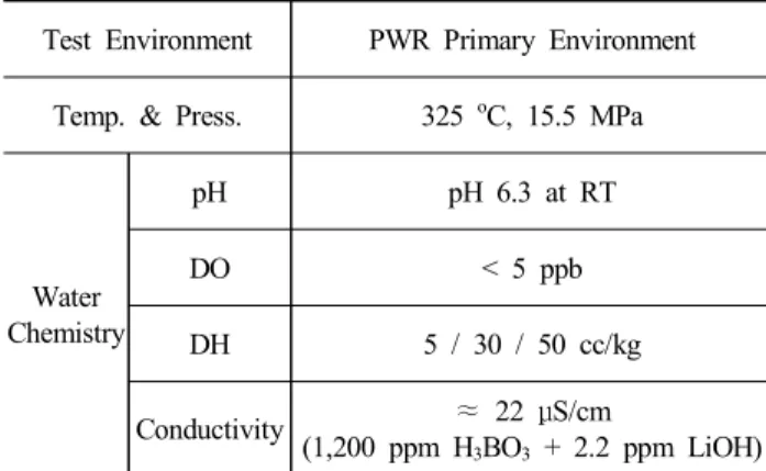
Table 2. Test environment and conditions
Test Environment PWR Primary Environment Temp. & Press. 325 oC, 15.5 MPa
Water Chemistry
pH pH 6.3 at RT
DO < 5 ppb
DH 5 / 30 / 50 cc/kg
Conductivity ≈ 22 μS/cm
(1,200 ppm H3BO3 + 2.2 ppm LiOH)
For crack initiation test, U-bend specimens were fab- ricated in T-L orientation, in which the loading direction is perpendicular to the dendrite orientation, as shown in Fig. 1. Then, a plate was bent 3 % in one direction, flattened, and then finally bent to 11.3 % and 19.2 % in the reverse direction. To provide constant stress on the apex of the specimen, the specimen was pushed by the spring. For oxide characterization, coupon-type specimens with 10 mm diameter were used. For in-situ EIS analysis tensile-loaded and zirconia coated speci- mens as shown in Fig. 2 were used.
2.2 Test Conditions and Methods
The specimens for oxide analysis were ground using emery papers down to 4000 grit, and U-bend specimens were grounded and polished by 1-μm diamond paste. All
of the specimens were ultrasonically cleaned using etha- nol and pure water before installing them into autoclaves for the experiments. To simulate a PWR environment, the once-through type water circulation loop was used.
The schematic diagram of the test set-up is shown in Fig. 3. Specimens were exposed to the simulated PWR water containing 1,200 ppm of boric acid and 2.2 ppm of lithium hydroxide for up to 1,000 hours. To inves- tigate the effects of dissolved hydrogen (DH) contents on the PWSCC and oxidation, 5cc/kg (low DH), 30cc/kg (close to current operation level), and 50cc/kg (high DH) conditions were used. The details of the test conditions are summarized in Table 2.
The oxide characteristics were ex-situ analysed using SEM, TEM, XRD, and x-ray photoelectron spectroscopy (XPS). In addition, EIS tests were performed to evaluate in-situ oxide characteristics by measurement of im- pedance properties. Tensile-loaded and zirconia coated specimens of Alloy 182 was installed in the autoclave as shown in Fig. 4. The AUEN (Gold Electrode-Non PTFE) reference electrode and the Pt counter electrode were used. The impedance measurements were per- formed using a Gamry® potentiostat system (Reference 3000) at the open circuit potential using a frequency range from 100 kHz to 1 mHz (10 points per decade) with perturbation amplitude of 10 mV RMS.
Fig. 3. Schematic diagram of test system.
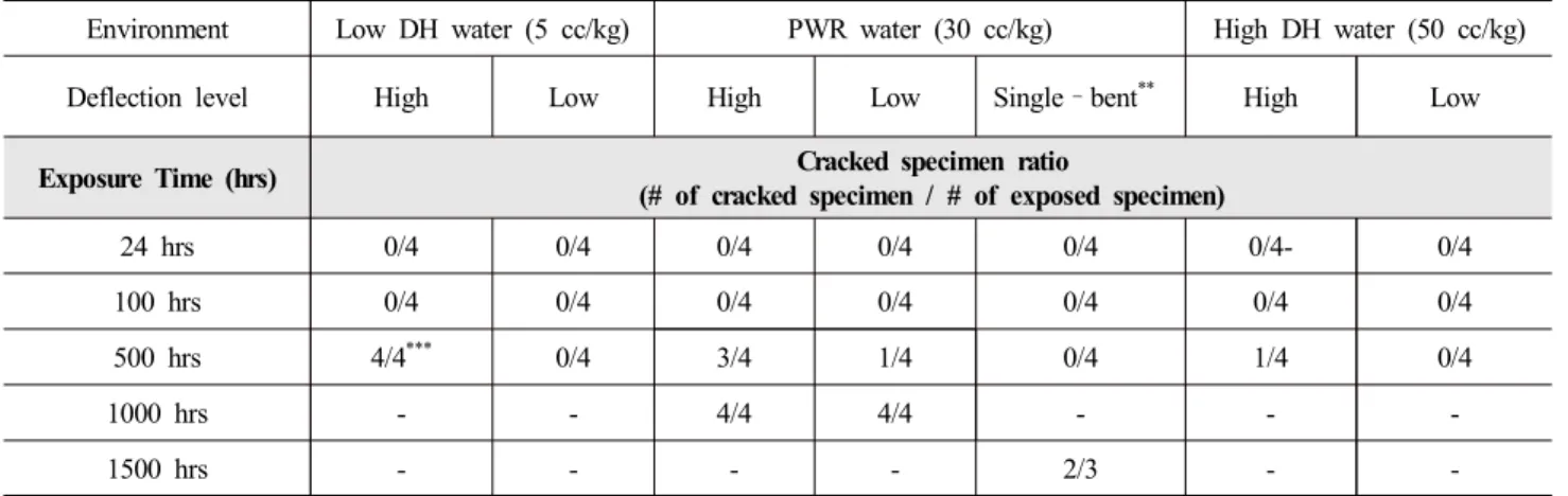
Table 3. Results of PWSCC initiation test with various DH level
Environment Low DH water (5 cc/kg) PWR water (30 cc/kg) High DH water (50 cc/kg)
Deflection level High Low High Low Single–bent** High Low
Exposure Time (hrs) Cracked specimen ratio
(# of cracked specimen / # of exposed specimen)
24 hrs 0/4 0/4 0/4 0/4 0/4 0/4- 0/4
100 hrs 0/4 0/4 0/4 0/4 0/4 0/4 0/4
500 hrs 4/4*** 0/4 3/4 1/4 0/4 1/4 0/4
1000 hrs - - 4/4 4/4 - - -
1500 hrs - - - - 2/3 - -
* High deflection ~ 19.2 %, Low deflection ~ 11.3 % (calculated by the equation on ASTM G3012))
** Single-bent ~ 12 % (only in one direction)
*** Some of cracks were initiated at weld defect
Fig. 4. Setup of the specimens installed in the autoclave for EIS test.
3. Resutls and Discussion
3.1 DH effect on PWSCC initiation property
Table 3 shows the current test results of PWSCC ini- tiation test using reverse U-bend specimens which are exposed to simulated PWR environment with various DH content 5, 30, 50 cc/kg up to 1,000 hours. Note that tests under Low DH and High DH condition are on- going. No cracks were found in the specimen of Alloy 182, but after 500 hours of exposure, until 100 hours exposure, some of the specimens showed cracks on the surface in 30 cc/kg of DH condition, which corresponds to typical PWR primary water environments. Eventually, cracks are initiated on the all of specimens exposed to
Fig. 5. Photos of PWSCC initiated cracks with different deflection in PWR water (DH: 30 cc/kg).
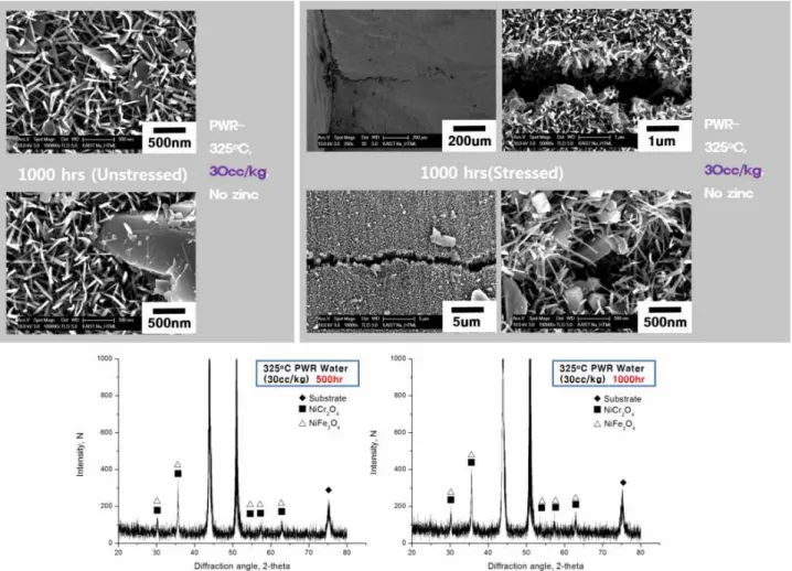
Fig. 6. SEM images and XRD analysis on oxide surface of Alloy 182 in PWR water (DH : 30 cc/kg).
30 cc/kg of DH level after 1,000 h. Also shown in the table is that as the level of deflection (level of stress) increased, the susceptibility to PWSCC increased. The
ing the crack length is about hundreds μm regardless of deflection level. In high DH condition, a relatively smaller crack is observed in one specimen with high de- flection level.
3.2 Ex-situ oxide analysis
Morphology and structure of the surface oxide were analysed by SEM and XRD. Previously, Combrade et.al reported that the composition of the external oxide layers for Alloy 600 and 690 strongly depended on the nature and surface condition of the base metal as well as the saturation of Fe and Ni cations in the aqueous environ- ment1). In this study, needle-like oxide and crystallites
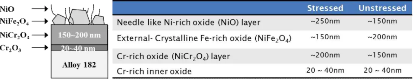
Fig. 7. Estimation for thickness of each oxide layer from SEM Analysis (DH: 30 cc/kg).
(a) Nyquist plot at high DH condition
(b) Bode(modulus) plot at high DH condition (c) Bode(phase) plot at high DH condition
(d) An equivalent circuit model (e) Fitting curve data(150 hours) Fig. 8. EIS analysis for Alloy 182 in PWR water (DH : 50 cc/kg, no zinc, 24, 50, 100, 150 hours).
From the XRD analysis on the surface, NiFe2O4 as well as NiCr2O4 peaks were observed and their intensities in- creased with the increase of exposure time.
In addition, internal Cr-rich oxide (NiCr2O4) layer (thickness ~ 300 nm) was observed under needle-like and crystallites oxide layer. It is reported that the Cr-rich inner layer comprises two “sub-layers” 1,2). In this study, it was found that the metal side of the sub-layer is Cr2O3
(or (Cr,Fe)2O3) oxide through XPS, and TEM-EDS analyses. Meanwhile, on the solution side, the sub-layer is much thicker and consisted of Cr rich spinel type oxides. Our observation results are consistent with the reported results1,2,13). The additional results at different DH levels would provide a better understanding of the role of DH on the oxidation behaviours of Alloy 182.
Meanwhile, the thickness of Ni-rich and Cr-rich oxide layer of the stressed specimen is slightly thicker than that of the unstressed specimen as shown in Fig. 7.
However, the overall oxide structures were the same re- gardless of the applied stress.
3.3 In-situ oxide analysis using EIS
The in-situ EIS analysis was performed on the Alloy 182 exposed to high DH condition (50 cc/kg) up to 150 hours and the results are shown in Fig. 8. In Nyquist plot, generally, semicircle is composed of resistance and capacitance in parallel. Specifically, large semicircles in Nyquist plot standing for charge transfer phenomena consisted of a charge transfer resistance, Rct, in parallel to an electric double layer capacitance, Cdl. It means that electron transfer reaction passes through interface be- tween electrode and electrolyte. As shown in the figure, increase in impedance was observed with the increase of exposure time on Nyquist plot and Bode-impedance plot, which implied an increase of surface film thickness.
Also, the shapes of semicircles in Nyquist plot are some- what depressed, probably due to the existence of defects and non-homogeneous part in the oxide film. Meanwhile, as an attempt to analyse the multi-layer structure of ox- ides, EIS data were fitted into an equivalent circuit model. For example, from the fitting data of exposure time 150hr, there is the possibility that two or three oxide layers exist on the metal surface approximately. Combrade et.al reported that the oxide structures divided into Cr-rich
4. Summary
In this study, the PWSCC behaviours of Alloy 182 weld were investigated in simulated PWR environments with various DH content. Both in-situ and ex-situ oxide characterizations as well as PWSCC initiation tests were performed. For ex-situ analysis, SEM/EDS, TEM, and XRD techniques were used. For in-situ analysis, oxide characteristics were analysed by EIS (Electrochemical Impedance Spectroscopy) test. Based on the tests and analyses, the following results were derived:
- Of the 3 DH levels, PWSCC crack initiation time was shortest in PWR water (DH: 30 cc/kg). Also, high stress reduced crack initiation time.
- Oxide layer showed multi-layered structures consisted of the outer needle-like Ni-rich oxide layer, Fe-rich crystalline oxide, and inner Cr-rich inner oxide layers, which was not altered by the level of applied stress - To analyse the multi-layer structure of oxides, EIS
measurement were fitted into an equivalent circuit model. Further analyses including TEM and EDS are underway to verify appropriateness of the equivalent circuit model.
Acknowledgments
This study was mainly supported by the KETEP- International Collaborative Energy Technology R&D Program (No. 20128540010010) of MOTIE of the Republic of Korea. Financial support for some authors was pro- vided by the BK-Plus Program of the MSIP of the Republic of Korea.
References
1. P. Combrade, P. M. Scott, M. Foucault, E. Andrieu and P. Marcus, Proceedings of the 12th International Conference on Environmental Degradation of Materials in Nuclear Power System -Water Reactors, p. 883, NACE, Salt Lake City, Utah (2005).
2. Sennour M, Marchetti L, Martin F, Perrin S, Molins R and Pijolat M, J. .Nucl. Mater., 402, 147 (2010).
3. A. Machet, A. Galtayries, S. Zanna, L. Klein, V. Maurice, P. Jolivet, M. Foucault, P. Combrade, P. Scott and P.
Marcus, Electrochim. Acta, 49, 3957 (2004).
4. B. T. Ovanessian, J. Deleume, J. M. Cloué, E. Andrieu, Mater. Sci. Forum, 595, 449 (2008).
5. L. Marchetti, S. Perrin, O. Raquet and M. Pijolat, Mater.
Sci. Forum, 595, 529 (2008).
6. L. Marchetti, S. Perrin, Y. Wouters and M. Pijolat, Electrochim. Acta, 55, 5384 (2010).
7. Y. Qiu, T. Shoji, Z. Lu, Corros. Sci., 53, 1983 (2011).
8. Q. Peng, J. Hou, K. Sakaguchi, Y. Takeda, T. Shoji, Electrochim. Acta, 56, 8375 (2011).
9. J. Kim, S. H. Kim, K. J. Choi, C. B. Bahn, I. S. Hwang, J. H. Kim, Corros. Sci., 86, 295 (2014).
10. ASME Sec II Part C - SFA-5.11/SFA-5.11M, ASME, New York (2010).
11. J-D Hong, J. Lee, C. Jang, J. H. Kim, T. Shoji, Present at NPC 2014, Sapporo, Japan (2014).
12. ASTM G30-97, ASTM, Philadelphia, Pennsylvania (2009).
13. K. Dozaki, D. Akutagawa, N. Nagata, H. Takiguchi, and K. Norring, E-Journal of Advanced Maintenance, 2, 65 (2010).