JPNT 4(4), 205-211 (2015)
http://dx.doi.org/10.11003/JPNT.2015.4.4.205
Copyright © The Korean GNSS Society
J PNT Journal of Positioning, Navigation, and Timing
http://www.gnss.or.kr Print ISSN: 2288-8187 Online ISSN: 2289-0866
1. INTRODUCTION
The Global Positioning System (GPS) from the United States is a Global Navigation Satellite System. It has been operated more than 30 years and has provided useful position and time information for users. GPS signals can be received anywhere at any time regardless of the weather condition, and thus have been used in various areas. In addition, the demand for GPS has gradually increased in the national defense and civilian areas, and it has become an important public social infrastructure.
As the economic/social/military usefulness of GPS has been emphasized, Russia has established and operated
Multi-GNSS Standard Point Positioning using GPS, GLONASS, BeiDou and QZSS Measurements Recorded at MKPO Reference Station in South Korea
Byung-Kyu Choi
1†, Chang-Hyun Cho
1, Jung Ho Cho
1, Sang Jeong Lee
21
Space Science Division, Korea Astronomy and Space Science Institute, Daejeon 305-348, Korea
2
Department of Electronics Engineering, Chungnam National University, Daejeon 305-764, Korea
ABSTRACT
The Global Navigation Satellite System (GNSS) is undergoing dramatic changes. Nowadays, much more satellites are transmitting navigation data at more frequencies. A multi-GNSS analysis is performed to improve the positioning accuracy by processing combined observations from different GNSS. The multi-GNSS technique can improve significantly the positioning accuracy. In this paper, we present a combined Global Positioning System (GPS), the GLObal NAvigation Satellite System (GLONASS), the China Satellite Navigation System (BeiDou), and the Quasi-Zenith Satellite System (QZSS) standard point positioning (SPP) method to exploit all currently available GNSS observations at Mokpo (MKPO) station in South Korea. We also investigate the multi-GNSS data recorded at MKPO reference station. The positioning accuracy is compared with several combinations of the satellite systems. Because of the different frequencies and signal structure of the different GNSS, inter- system biases (ISB) parameters for code observations have to be estimated together with receiver clocks in multi-GNSS SPP.
We also present GPS/GLONASS and GPS/BeiDou ISB values estimated by the daily average.
Keywords: GNSS, multi, position accuracy, ISB
a system called GLObal NAvigation Satellite System (GLONASS), and the European Union and China have established Global Navigation Satellite Systems called Galilleo and China Satellite Navigation System (BeiDou), respectively. In the case of GPS, 31 satellites are currently operated; and in the case of GLONASS, all the 24 navigation satellites have been operated since the end of 2011. Galileo from the European Union is expected to have 30 medium Earth orbit satellites, and six navigation satellites are currently operated. In the case of BeiDou, 14 satellites are currently operated, and a total of 35 satellites are planned to be launched by 2020 (BeiDou ICD 2013). To take the lead in the satellite navigation system area, many countries have competed for prompt system establishment and performance improvement in recent years.
Japan has been developing a local satellite navigation system called Quasi-Zenith Satellite System (QZSS), and one satellite is currently operated (IS-QZSS 2014). QZSS covers the Asia-Oceania region. In particular, it is expected Received Aug 10, 2015 Revised Sep 21, 2015 Accepted Oct 13, 2015
†
Corresponding Author E-mail: [email protected]
Tel: +82-42-865-3237 Fax: +82-42-861-5610
206 JPNT 4(4), 205-212 (2015)
http://dx.doi.org/10.11003/JPNT.2015.4.4.205
to play an important role in securing positioning availability from high elevation angles.
A Global Navigation Satellite System (GNSS) can provide more accurate and precise information, such as geodetic survey, navigation, and time. It is expected that GNSS navigation signals from at least 35 satellites could be received in the Asia-Oceania region after 2020. GNSS would lead to the improvement in positioning accuracy, reliability, and satellite availability, compared to the solution of an individual satellite navigation system such as GPS.
Until recently, studies on combined positioning have been limited to GPS and GLONASS (Cai & Gao 2007, Li et al. 2009, Tolman et al. 2010). However, as the BeiDou and Galileo satellites have recently provided navigation signals, studies on positioning that combine BeiDou or Galileo satellite observations with an existing system have been performed (He et al. 2013, Tegedor et al. 2014, Santerre et al. 2014, Cai et al. 2014, Li et al. 2015). Santerre et al.
(2014) reported a position accuracy performance of less than about 5 m by combining GPS, GLONASS, and BeiDou observations received within China, and also separately analyzed the position accuracy performance depending on the elevation cutoff of the satellites.
In the East Asian region, many navigation signals can be received from the GPS stations due to the recent operation of the regional satellite navigation system from China with GPS and GLONASS. One QZSS satellite is in operation, and thus it is needed to analyze positioning accuracy using these signals received in South Korea.
For the performance experiment of the Galileo and BeiDou systems, existing studies investigated position accuracy depending on the combination of the satellite constellation by limiting to Europe and the China regions.
In the present study, position accuracy performance was analyzed through various combinations of satellite observations received in South Korea. In particular, position accuracy was analyzed through the combination of QZSS satellite data with GPS, GLONASS, and BeiDou.
In the present study, receiver intersystem biases were also analyzed. The position accuracy performance of the GPS/GLONASS/BeiDou/QZSS combination at the Mokpo (MKPO) reference station in the Korean Peninsula was compared with those of other combinations, and the results were presented.
2. PROCESSING STRTEGY AND METHODS
GPS uses two L bands (L1 ~ 1,575.42 MHz and L2 ~ 1,227.60 MHz), and GLONASS provides information for
users using two frequency bands, f
L1= (1602 + n × 0.5625) MHz and f
L2= (1246 + n × 0.4375) MHz (GLONASS ICD 2008). In this regard, n is the frequency channel number. In addition, BeiDou satellites transmit three frequencies (B1
~ 1,561.098 MHz, B2 ~ 1,207.140 MHz, and B3 ~ 1,268.520 MHz) (BeiDou ICD 2013), and QZSS uses signals identical to those of GPS.
In this study, GPS L1 C/A (Coarse/Acquisition) code, GLONASS L1 code, BeiDou B1 code, and QZSS L1 code were used to process the GPS, GLONASS, BeiDou, and QZSS observations. Eq. (1) shows the measurement equation using GNSS code phases.
performance of the GPS/GLONASS/BeiDou/QZSS combination at the Mokpo (MKPO) reference station in the Korean Peninsula was compared with those of other combinations, and the results were presented.
2. PROCESSING STRTEGY AND METHODS
GPS uses two L bands (L1 ~ 1,575.42 MHz and L2 ~ 1,227.60 MHz), and GLONASS provides information for users using two frequency bands, f
L1= (1602 + n × 0.5625) MHz and f
L2= (1246 + n × 0.4375) MHz (GLONASS ICD 2008). In this regard, n is the frequency channel number. In addition, BeiDou satellites transmit three frequencies (B1 ~ 1,561.098 MHz, B2 ~ 1,207.140 MHz, and B3 ~ 1,268.520 MHz) (BeiDou ICD 2013), and QZSS uses signals identical to those of GPS.
In this study, GPS L1 C/A (Coarse/Acquisition) code, GLONASS L1 code, BeiDou B1 code, and QZSS L1 code were used to process the GPS, GLONASS, BeiDou, and QZSS observations. Eq.
(1) shows the measurement equation using GNSS code phases.
𝑃𝑃
𝑖𝑖𝑗𝑗= 𝜌𝜌
𝑗𝑗+ 𝑐𝑐𝑐𝑐𝑐𝑐 + 𝐼𝐼𝐼𝐼𝐼𝐼
𝑗𝑗− 𝑐𝑐𝑐𝑐𝑑𝑑
𝑗𝑗+ 𝑐𝑐
𝑡𝑡𝑡𝑡𝑡𝑡𝑡𝑡𝑗𝑗+ 𝑐𝑐
𝑖𝑖𝑡𝑡𝑖𝑖𝑡𝑡/𝐿𝐿𝑗𝑗 𝑖𝑖+ 𝜀𝜀
𝑃𝑃𝑗𝑗𝑖𝑖(1)
where the superscript j represents the GNSS satellite. 𝜌𝜌 is the geometry range between the satellite and the receiver, and dt and dT are the clock errors of the receiver and the satellite, respectively. ISB is the intersystem bias; GPS/GLONASS and GPS/BeiDou, and c is the speed of light. d
tropis the tropospheric delay error, and d
iono/Liis the ionospheric delay error of the GNSS satellite having the i-th frequency. 𝜀𝜀
𝑃𝑃𝑖𝑖includes the receiver noise and the multipath error.
In this study, the Klobuchar model that is used for GPS was utilized to calculate ionospheric delay error, and the ionospheric delay values depending on the frequency of the GNSS satellite was calculated and applied as shown in Eq. (2) based on the fact that ionospheric delay error is inversely proportional to the square of the strength of frequency.
1 2
/i
i GPS L iono L
GLSS L
d f Klob
f
念 ÷
ç ÷
=ççç曜 ÷÷÷g
(2)
where 𝑓𝑓
𝐺𝐺𝑃𝑃𝐺𝐺 𝐿𝐿1includes the GPS L1 frequency, and 𝑓𝑓
𝐺𝐺𝐺𝐺𝐺𝐺𝐺𝐺 𝐿𝐿𝑖𝑖includes the GPS L1, GLONASS L1, BeiDou B1, and QZSS L1 frequencies. Klob is the ionospheric delay value calculated by the Klobuchar model. Unlike GPS, BeiDou, and QZSS, the GLONASS system is operated based on frequency division, and thus the frequency for each satellite was determined after recognizing the
(1)
where the superscript j represents the GNSS satellite. ρ is the geometry range between the satellite and the receiver, and and dT are the clock errors of the receiver and the satellite, respectively. ISB is the intersystem bias; GPS/
GLONASS and GPS/BeiDou, and c is the speed of light. d
tropis the tropospheric delay error, and d
iono/Liis the ionospheric delay error of the GNSS satellite having the i-th frequency.
ε
Piincludes the receiver noise and the multipath error.
In this study, the Klobuchar model that is used for GPS was utilized to calculate ionospheric delay error, and the ionospheric delay values depending on the frequency of the GNSS satellite was calculated and applied as shown in Eq.
(2) based on the fact that ionospheric delay error is inversely proportional to the square of the strength of frequency.
GPS uses two L bands (L1~1,575.42MHz and L2~1,227.60MHz), and GLONASS provides information for users using two frequency bands, 𝑓𝑓
𝐿𝐿1= (1602 + 𝑛𝑛 × 0.5625)𝑀𝑀𝑀𝑀𝑀𝑀 and 𝑓𝑓
𝐿𝐿2= (1246 + 𝑛𝑛 × 0.4375)𝑀𝑀𝑀𝑀𝑀𝑀 (GLONASS ICD, 2008). In this regard, n is the frequency channel number. In addition, BeiDou satellites transmit three frequencies (B1~1,561.098MHz, B2~1,207.140MHz, and B3~1,268.520MHz) (BeiDou ICD, 2013), and QZSS uses signals identical to those of GPS.
In this study, GPS L1 C/A (Coarse/Acquisition) code, GLONASS L1 code, BeiDou B1 code, and QZSS L1 code were used to process the GPS, GLONASS, BeiDou, and QZSS observations. Eq.
(1) shows the measurement equation using GNSS code phases.
𝑃𝑃
𝑖𝑖𝑗𝑗= 𝜌𝜌
𝑗𝑗+ 𝑐𝑐𝑐𝑐𝑐𝑐 + 𝐼𝐼𝐼𝐼𝐼𝐼
𝑗𝑗− 𝑐𝑐𝑐𝑐𝑑𝑑
𝑗𝑗+ 𝑐𝑐
𝑡𝑡𝑡𝑡𝑡𝑡𝑡𝑡𝑗𝑗+ 𝑐𝑐
𝑖𝑖𝑡𝑡𝑖𝑖𝑡𝑡/𝐿𝐿𝑗𝑗 𝑖𝑖+ 𝜀𝜀
𝑃𝑃𝑗𝑗𝑖𝑖(1)
where the superscript j represents the GNSS satellite. 𝜌𝜌 is the geometry range between the satellite and the receiver, and dt and dT are the clock errors of the receiver and the satellite, respectively.
𝐼𝐼𝐼𝐼𝐼𝐼 is the intersystem bias; GPS/GLONASS and GPS/BeiDou, and c is the speed of light. 𝑐𝑐
𝑡𝑡𝑡𝑡𝑡𝑡𝑡𝑡is the tropospheric delay error, and 𝑐𝑐
𝑖𝑖𝑡𝑡𝑖𝑖𝑡𝑡/𝐿𝐿𝑖𝑖is the ionospheric delay error of the GNSS satellite having the i-th frequency. 𝜀𝜀
𝑃𝑃𝑖𝑖includes the receiver noise and the multipath error.
In this study, the Klobuchar model that is used for GPS was utilized to calculate ionospheric delay error, and the ionospheric delay values depending on the frequency of the GNSS satellite was calculated and applied as shown in Eq. (2) based on the fact that ionospheric delay error is inversely proportional to the square of the strength of frequency.
𝑐𝑐
𝑖𝑖𝑡𝑡𝑖𝑖𝑡𝑡/𝐿𝐿𝑖𝑖= (
𝑓𝑓𝑓𝑓𝐺𝐺𝐺𝐺𝐺𝐺 𝐿𝐿1𝐺𝐺𝐿𝐿𝐺𝐺𝐺𝐺 𝐿𝐿𝑖𝑖
)
2∙ 𝐾𝐾𝐾𝐾𝐾𝐾𝐾𝐾 (2)
where 𝑓𝑓
𝐺𝐺𝑃𝑃𝐺𝐺 𝐿𝐿1includes the GPS L1 frequency, and 𝑓𝑓
𝐺𝐺𝐺𝐺𝐺𝐺𝐺𝐺 𝐿𝐿𝑖𝑖includes the GPS L1, GLONASS L1, BeiDou B1, and QZSS L1 frequencies. Klob is the ionospheric delay value calculated by the Klobuchar model. Unlike GPS, BeiDou, and QZSS, the GLONASS system is operated based on frequency division, and thus the frequency for each satellite was determined after recognizing the channel number for each satellite from the navigation file.
To estimate the position, receiver clock error, and the intersystem bias, the weighted least squares method was employed as Eq. (3) (Paula et al. 2011).
𝑋𝑋⃑ = (𝑀𝑀
𝑇𝑇𝑊𝑊𝑀𝑀)
−1𝑀𝑀
𝑇𝑇𝑊𝑊𝑣𝑣⃑ (3) (2)
where f
GPS L1includes the GPS L1 frequency, and f
GNSS Liincludes the GPS L1, GLONASS L1, BeiDou B1, and QZSS L1 frequencies. Klob is the ionospheric delay value calculated by the Klobuchar model. Unlike GPS, BeiDou, and QZSS, the GLONASS system is operated based on frequency division, and thus the frequency for each satellite was determined after recognizing the channel number for each satellite from the navigation file.
To estimate the position, receiver clock error, and the intersystem bias, the weighted least squares method was employed as Eq. (3) (Tarrío et al. 2011).
channel number for each satellite from the navigation file.
To estimate the position, receiver clock error, and the intersystem bias, the weighted least squares method was employed as Eq. (3) (
Tarríoet al. 2011).
𝑋𝑋⃑ = (𝐻𝐻
𝑇𝑇𝑊𝑊𝐻𝐻)
−1𝐻𝐻
𝑇𝑇𝑊𝑊𝑣𝑣⃑ (3)
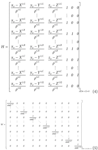
(4)
(3)
Byung-Kyu Choi et al. Multi-GNSS Standard Point Positioning Article type: Technical Paper 207
http://www.gnss.or.kr
channel number for each satellite from the navigation file.
To estimate the position, receiver clock error, and the intersystem bias, the weighted least squares method was employed as Eq. (3) (Tarrío et al. 2011).
𝑋𝑋⃑ = (𝐻𝐻𝑇𝑇𝑊𝑊𝐻𝐻)−1𝐻𝐻𝑇𝑇𝑊𝑊𝑣𝑣⃑ (3)
(4)
(4)
(5)
where H is the design matrix, and W is the weighted matrix depending on the satellite elevation angle (𝐸𝐸) and it is expressed in Eq. (5). In Eq. (5), additional weighting factor depending on the satellite constellation was not applied. nv
is the pseudorange residual vector. G, R, C, and Q represent the GPS, GLONASS, BeiDou, and QZSS, respectively. In Eq. (4), if GPS, GLONASS, BeiDou and one QZSS satellite are received, the size of the design matrix, H, is (3n + 1) × 6, and the residual vector,
nv
, is 3n + 1. The final solution is X = {𝑥𝑥, 𝑦𝑦, 𝑧𝑧, 𝑑𝑑𝑑𝑑, 𝐼𝐼𝐼𝐼𝐼𝐼𝐺𝐺−𝑅𝑅, 𝐼𝐼𝐼𝐼𝐼𝐼𝐺𝐺−𝐶𝐶}.
A key for data processing is to establish the reference time system and the reference coordinate system. For the reference time system, both GPS and QZSS use the GPS time (GPST), and BeiDou uses the BeiDou Time (BDT), which has a difference of 14 seconds from GPST (BeiDou ICD 2013).
GLONASS uses the Coordinated Universal Time (UTC). In the case of the reference coordinate system, the World Geodetic System 84 (WGS 84) for the GPS was applied. BeiDou and QZSS use reference coordinate systems called the China Geodetic Coordinate System 2000 (CGCS2000) and the Japan satellite navigation Geodetic System (JGS), respectively, but CGCS2000 and JGS do not provide parameters for a transformation of the reference coordinate system to WGS84. Therefore, in this study, it was assumed that CGCS2000 and JGS are identical to WGS84. GLONASS uses a reference coordinate system called the Parametry Zemli 1990 (PZ-90); and to convert PZ-90 into WGS84, Eq. (6) was separately applied.
3 2 1
3 1 2
2 1 3
x' x x
y' y y
z' z z
D R R T
R D R T
R R D T
念判念 念 - 判念 念?
霓判 霓 判 ? ?
霓判 霓 判 ? ?
霓判= +霓 - 判 +? ?
霓判 霓 判 ? ?
霓判 霓 判 ? ?
霓判判 霓 判判 ? ??
霓 霓- ?
曜 曜 曜 曜 曜
(6)
(5)
where H is the design matrix, and W is the weighted matrix depending on the satellite elevation angle (E) and it is expressed in Eq. (5). In Eq. (5), additional weighting factor depending on the satellite constellation was not applied. ň is the pseudorange residual vector. G, R, C, and Q represent the GPS, GLONASS, BeiDou, and QZSS, respectively. In Eq.
(4), if GPS, GLONASS, BeiDou and one QZSS satellite are received, the size of the design matrix, H, is (3n + 1) × 6, and the residual vector, ň, is 3n + 1. The final solution is X = {x, y, z, dt, ISB
G-R, ISB
G-C}.
A key for data processing is to establish the reference time system and the reference coordinate system. For the reference time system, both GPS and QZSS use the GPS time (GPST), and BeiDou uses the BeiDou Time (BDT), which has a difference of 14 seconds from GPST (BeiDou ICD 2013). GLONASS uses the Coordinated Universal Time (UTC). In the case of the reference coordinate system, the World Geodetic System 84 (WGS 84) for the GPS was applied. BeiDou and QZSS use reference coordinate systems called the China Geodetic Coordinate System 2000 (CGCS2000) and the Japan satellite navigation Geodetic System (JGS), respectively, but CGCS2000 and JGS do not provide parameters for a transformation of the reference
coordinate system to WGS84. Therefore, in this study, it was assumed that CGCS2000 and JGS are identical to WGS84.
GLONASS uses a reference coordinate system called the Parametry Zemli 1990 (PZ-90); and to convert PZ-90 into WGS84, Eq. (6) was separately applied.
satellite constellation was not applied. is the pseudorange residual vector. 𝐺𝐺, 𝑅𝑅, 𝐶𝐶, 𝑎𝑎𝑎𝑎𝑑𝑑 𝑄𝑄 represent the GPS, GLONASS, BeiDou, and QZSS, respectively. In Eq. (4), if GPS, GLONASS, BeiDou and one QZSS satellite are received, the size of the design matrix, 𝐻𝐻, is (3n+1)x6, and the residual vector, , is 3n+1. The final solution is X = {𝑥𝑥, 𝑦𝑦, 𝑧𝑧, 𝑑𝑑𝑑𝑑, 𝐼𝐼𝐼𝐼𝐼𝐼𝐺𝐺−𝑅𝑅, 𝐼𝐼𝐼𝐼𝐼𝐼𝐺𝐺−𝐶𝐶}.
A key for data processing is to establish the reference time system and the reference coordinate system. For the reference time system, both GPS and QZSS use the GPS time (GPST), and BeiDou uses the BeiDou Time (BDT), which has a difference of 14 seconds from GPST (BeiDou ICD, 2013).
GLONASS uses the Coordinated Universal Time (UTC). In the case of the reference coordinate system, the World Geodetic System 84 (WGS 84) for the GPS was applied. BeiDou and QZSS use reference coordinate systems called the China Geodetic Coordinate System 2000 (CGCS2000) and the Japan satellite navigation Geodetic System (JGS), respectively, but CGCS2000 and JGS do not provide parameters for a transformation of the reference coordinate system to WGS84. Therefore, in this study, it was assumed that CGCS2000 and JGS are identical to WGS84. GLONASS uses a reference coordinate system called the Parametry Zemli 1990 (PZ-90); and to convert PZ-90 into WGS84, Eq. (6) was separately applied.
(6)
where (x’, y’, z’) are the WGS84 reference coordinate values, and (x, y, z) are the PZ-90 reference coordinate values. For a transformation both the two reference coordinate systems, seven parameters {𝑇𝑇1, 𝑇𝑇2, 𝑇𝑇3, 𝐷𝐷, 𝑅𝑅1, 𝑅𝑅2, 𝑅𝑅3} are required. For the values of {𝑇𝑇1, 𝑇𝑇2, 𝑇𝑇3}, {0.07m, 0.00m, 0.77m} were used; for the value of D, -3 parts per billion was used; and for the values of {𝑅𝑅1, 𝑅𝑅2, 𝑅𝑅3}, {-19, -4, 353}
were used (http://www.navipedia.net/index.php/Reference_Frames_in_GNSS). The units of {𝑅𝑅1, 𝑅𝑅2, 𝑅𝑅3} are mili-arc seconds.
Table 1 summarizes the reference time system and the reference coordinate system used for each satellite navigation system, and it also includes the maximum number of satellites (the number of currently available satellites), orbital plane, orbital inclination, average orbital altitude, and the rotation period of the satellite.
(6)
where (x', y', z') are the WGS84 reference coordinate values, and (x, y, z) are the PZ-90 reference coordinate values. For a transformation both the two reference coordinate systems, seven parameters {T
1, T
2, T
3, D, R
1, R
2, R
3} are required. For the values of {T
1, T
2, T
3}, {0.07m, 0.00m, 0.77m} were used;
for the value of D, -3 parts per billion was used; and for the values of {R
1, R
2, R
3}, {-19, -4, 353} were used (http://www.
navipedia.net/index.php/Reference_Frames_in_GNSS).
The units of {R
1, R
2, R
3} are mili-arc seconds.
Table 1 summarizes the reference time system and the reference coordinate system used for each satellite navigation system, and it also includes the maximum number of satellites (the number of currently available satellites), orbital plane, orbital inclination, average orbital altitude, and the rotation period of the satellite.
3. RESULTS
To analyze the performance of combined positioning, measurements received at the MKPO GNSS reference station operated by the Korea Astronomy and Space Science Institute were used. For the MKPO GNSS reference station, Trimble NetR9 receiver and TRM59800 antenna have been installed and operated. The Trimble NetR9 receiver used for the experiment can receive GPS, GLONASS, BeiDou, Galileo, and QZSS satellite signals. In addition, the obtained data were converted to a Receiver Independent Exchange format (version, “extended 2.11”). We analyzed observations with the variations in the number of visible satellites over the Korean Peninsula depending on time.
Fig. 1 shows the variations in the number of visible Table 1. Characteristics of GNSS system.
System GPS GLONASS BeiDou QZSS
Number of satellites Orbital planes Orbital inclination (deg) Orbital altitude (km) Period of revolution Time scale Coordinate system Ephemeris update (h)
32 (31) 6 55 20,197 11
h58
mGPST WGS84 Every 2
24 (24) 3 65 19,130 11
h16
mUTC PZ90 Every 0.5
35 (14) 3 55 21,540 12
h53
mBDT CGCS2000 Every 1
4 (1)
3
43
35,786
23
h56
mGPST
JGS
Every 1
208 JPNT 4(4), 205-212 (2015)
satellites for GPS, GLONASS (GLO), BeiDou (BDS), and QZSS (QZS), respectively, and the variations in the number of all the satellites depending on time at 15 minute intervals using data received at the MKPO GNSS reference station on June 1, 2014. In Fig. 1, the vertical axis represents the number of visible satellites, and the horizontal axis represents the Universal Time.
The variations in the number of visible satellites for GPS were expressed as green diamonds. For GPS, the maximum number of visible satellites was 12 at 03:00 UT; and during the day, at least six satellites were continuously observed.
For GLONASS (GLO), the number of visible satellites was between 4 and 9 on the day. For BeiDou (BDS), the number of visible satellites was between 7 and 10 (expressed as red triangles). BDS had more visible satellites on average compared to GLO in the Korean Peninsula. For QZSS (QZS), the number of visible satellites was one, and a signal was not received from 19:00 to 23:00 UT. This is because the satellite cutoff angle for the receiver was set to 10 degrees.
The number of visible satellites for GPS+GLO+BDS+QZS was between 19 and 29 (expressed as gray squares), and the difference in the number of observed satellites depending on time was up to 10. In addition, for the MKPO GNSS reference station, relatively more navigation satellites were observed in the daytime than in the nighttime.
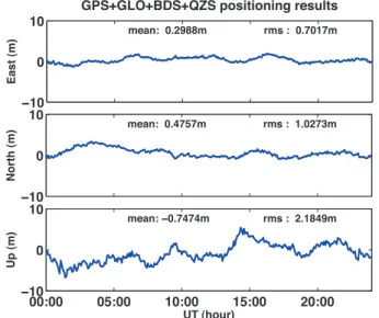
Combined positioning results were obtained by processing the multi-GNSS data received at the MKPO GNSS reference station. Fig. 2 shows the results of the standard point positioning using only single-frequency code phase. The position errors depending on time were presented as the east, north, and up direction components.
The absolute position for the position error was obtained based on the static precise point positioning (PPP)
method using the GNSS software developed by the Korea Astronomy and Space Science Institute. As shown in Fig.
2, the average values of the daily position errors calculated by the GPS+GLO+BDS+QZS combined positioning were 0.29 m, 0.47 m, and -0.74 m in the east, north, and up directions, respectively. Also, the average position errors in the horizontal directions (east and north) were smaller than that in the vertical direction (up). In the case of the root mean square (RMS) values for the position errors, the position accuracy in the horizontal direction was also outstanding, similar to the average position errors.
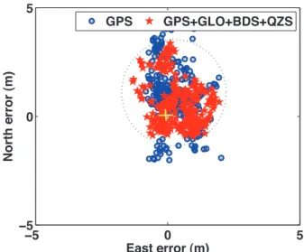
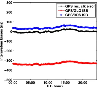
To analyze the position accuracy in the horizontal direction, the result of the GPS+GLO+BDS+QZS combined positioning was compared with that of the GPS-only positioning. In Fig. 3, the horizontal position errors shown in Fig. 2 and the horizontal position errors calculated using only GPS are presented, respectively. In Fig. 3, the horizontal axis represents the position error in the east direction, the vertical axis represents the position error in the north direction, and the yellow cross represents the absolute position (0, 0). The horizontal position errors of GPS were expressed as blue circles, and those of GPS+GLO+BDS+QZS were expressed as red stars. As shown in Fig. 3, all the horizontal position errors of the GPS+GLO+BDS+QZS combined positioning were smaller than those of the GPS-only positioning. In particular, the position error in the north direction decreased further compared to the horizontal components. The fact that the position error in the north direction is large can be caused by geometry of the satellites.
To analyze the positioning performance in various combinations of satellites, data processing is performed Fig. 1. GNSS visible satellites at MKPO reference station on 1 June 2014.
Fig. 2. Combined GPS+GLO+BDS+QZS standard point positioning error.
Byung-Kyu Choi et al. Multi-GNSS Standard Point Positioning Article type: Technical Paper 209
http://www.gnss.or.kr based on a total of five experiment groups. The experiment
groups included ‘GPS-only’, ‘GPS+BDS’, ‘GPS+GLO’,
‘GPS+GLO+BDS’, and ‘GPS+GLO+BDS+QZS’.
Fig. 4 shows the RMS values of the position errors calculated based on the experiment groups. In Fig. 4, the horizontal axis represents the RMS value for the position error, and the vertical axis represents the east, north, and up direction components. For the ‘GPS+BDS’
combination, the RMS value in the east direction increased by 0.03 m compared to that of ‘GPS-only’, while the RMS values in the north and up directions decreased. Thus, the overall position error decreased compared to that of the ‘GPS-only’ positioning. On the other hand, for the
‘GPS+GLO’ combination, the RMS values in the east and up directions showed the largest errors compared to those of the other experiment groups. The RMS values in the
north component are smaller than those of ‘GPS-only’
and ‘GPS+BDS’. The results indicated that the ‘GPS+GLO’
combination had a larger RMS value for the position error than ‘GPS-only’. Choi et al. (2013) reported that the GPS and GLONASS combination did not show improved positioning performance within the Korean Peninsula compared to GPS-only positioning. These results of the present study are consistent with the results of the previous study. This could be because GLONASS signals had large noise or the transformation parameters between different reference coordinate systems are not appropriate for the Korean Peninsula in the mid-latitudes. Therefore, transformation parameters for reference coordinate systems need to be directly estimated by the long-term data processing in global.
For the ‘GPS+GLO+BDS’ combination, the RMS values in all directions decreased compared to those of the ‘GPS+GLO’ combination. In particular, the difference in the RMS value in the up direction was about 0.6 m, which showed a significant decrease. For the ‘GPS+GLO+BDS+QZS’ combination, the RMS values in the north and up directions decreased excluding the east direction. When one QZS satellite was added to the ‘GPS+GLO+BDS’, the RMS value in the up direction decreased further. As a result, the ‘GPS+GLO+BDS+QZS’
combination affected the position accuracy in the north and up directions.
The analysis of the position precision in the various combinations indicated that the ‘GPS+GLO’ combination showed relatively lower position precision compared to the other combinations, while the ‘GPS+GLO+BDS+QZS’
combination showed higher position precision.
Table 2 summarizes the average daily position errors calculated by each combination shown in Fig. 4. For the
‘GPS+GLO’ combination, the average position errors in the east and up directions relatively increased compared to those of other combinations. An increase of the averaged position errors in specific directions was consistent with an increase in the RMS values. On the other hand, the position error in the north direction was the smallest compared to those of other combinations. In addition, for the ‘GPS+GLO+BDS+QZS’ combination, the position errors Fig. 3. Comparison of the horizontal position errors between GPS and
GPS+GLO+BDS+QZS.
East North Up
0 1 2 3 4 5
RMS error (m)
GPS only GPS+BDS GPS+GLO GPS+GLO+BDS GPS+GLO+BDS+QZS
Fig. 4. Position RMS errors calculated by multi-GNSS combinations.
Table 2. Comparison of position errors within 95% confidence level.
Method Mean errors (m) RMS errors (m) East North Up East North Up