CSR-BC와 Harmonized CSR-BC의 선체 전단 응력에 대한 비교 고찰
박종민†・이규호・이상복・신성광 STX조선해양 구조설계팀1
A study on hull girder shear strength in bulk carriers for CSR and Harmonized CSR
Jong Min Park†・Kyu Ho Lee・Sang Bok Lee・Sung-Kwang Shin Initial Structure Design Team, STX Offshore & Shipbuilding
This is an Open-Access article distributed under the terms of the Creative Commons Attribution Non-Commercial License(http://creativecommons.org/licenses/by-nc/3.0) which permits unrestricted non-commercial use, distribution, and reproduction in any medium, provided the original work is properly cited.
Common Structural Rules (CSR) about bulk carriers and double-hull oil tankers of International Association of Classification Societies (IACS) has been applied to ships contracted for construction since April 2006. By unifying each society’s rules, the difference of opinion in the between shipyard and ship owners, classification was reduced, and CSR has been evaluated by rules the safety structure more enhanced. However, The CSR about the bulk carriers and double hull oil tankers, important design content standards, such as the local scantling calculation, static/dynamic load case and corrosion margin and etc., are different. Therefore in order to combine the CSR, the Harmonized CSR for bulk carriers and double hull oil tankers (H-CSR) was issued on 1, January, 2014, and will be apply to ships contracted for construction after 1st July 2015. It is necessary to verify the H-CSR to optimize the structural arrangement because effective date is not far off. In this study, we compared the impact by rule change for the hull girder shear strength of bulk carriers between CSR and H-CSR in respect of the yielding and buckling strength.
Keywords : Hull girder shear(선체 전단력), Local scantling calculation(부재 치수 산정법), Static/dynamic load (정적/동적 하중), Corrosion margin(부식 마진), Yield strength(항복 강도), Buckling strength(좌굴 강도)
1. 서 론
이중선체유조선 및 산적화물선에 대한 International Association of Classification Societies (IACS) 의 공통구조규칙(common structural Rules, 이하 CSR)은 2006년 4월 이후 건조 계약된 선박에 적용되어 오고 있다.
이는 각 선급 별로 나뉘어진 규칙을 일원화함으로써 선주, 선급, 조선소간 설계 및 건조에 있어서 이견 차이를 좁히며, 각 선급의 구조규칙에 비해 강화된 안전성을 주는 구조규칙으 로 평가 받고 있다. 하지만 두 선종에 대한 CSR은 동적/정적 하중, 부식 마진, 구조 부재 치수 산정 법 등 대다수의 설계 및 건조 핵심적인 내용이 상이하다.
이에 이중선체유조선 및 산적화물선의 CSR 통합이 대두되 었으며, 통합공통구조규칙(Common structural Rules BC &
OT, 이하 H-CSR)은 2012년 7월 1st External Draft가 발간되 었다. IMO 최종 승인을 통하여 2014년 1월 1일 1st Issued 되
었으며 이는 2015년 7월 1일 건조 계약 기준으로 발효된다.
현재 새로운 규칙을 적용하여야 되는 시점에서 설계자는 Rule 분석 및 수많은 사례 연구를 통하여 H-CSR의 경향을 파 악하고 자료를 통계화하여 구조 배치를 최적화 시키고 이를 바 탕으로 선체 중량 과 부재수의 증가를 최소화 해야 할 것이다.
또한 통계화 된 자료는 설계 기간을 단축 시켜 줄 것이다.
본 연구에서는 CSR과 H-CSR의 선체 전단 응력(Hull girder shear) 부분을 비교 고찰을 수행하였으며, 선체 전단 력에 의한 응력 (Yield strength) 측면과 좌굴 (Buckling strength) 측면으 로 나뉘어 Rule 변경사항, 영향, 이에 따른 개선 사항 등을 연구 하였다.
2. 전단 응력 강도
Single side bulk carrier의 CSR 설계 기준 허용 전단 응력은 아래와 같다.
2015년 9월 pp. 46-49, September 2015 대한조선학회 특별논문집
Special Issue of the Society of Naval Architects of Korea
† 교신저자 : [email protected], 055-548-7815
박종민・이규호・이상복・신성광
Special Issue of SNAK, September 2015 47
∆
・
(1)
여기서, τ는 허용 전단 응력, S는 1차 모멘트, Iy는 2차 모멘 트, t는 Side shell minimum net thickness이다.
아래는 H-CSR 설계 기준 허용 전단 응력이다.
min
・
・
(2)
여기서,
는 Side shell minimum net thickness,
는 허용 전단 응력,
는 Unit shear flow,
는 Total vertical hull girder shear capacity로 아래의 식으로 정의를 한다.
∆
(3) 두 식 (1)와 (2)을 비교하기 위하여 동일 변수인 Plate net thickness에 관한 함수로 다음과 같이 유도할 수 있다.
∆
・ (4)
∆
・ min
・
(5)여기서, ∆
와 ∆
는 Shear force correction (이하
) 값이며 아래의 식으로 정의를 한다.∆
(6)∆
(7)여기서, 식 (7)의
는 Distribution coefficient 이며 아래와 같다.-
= -1 at the aft end of the considered cargo hold except for aftmost cargo hold.-
= 1 at the fore end of the considered cargo hold except for foremost cargo hold.-
= 0 at mid-length of the cargo hold.CSR과 H-CSR의 허용 전단 응력 식을 비교해보았을 때 두 Rule은 동일한 Formula를 사용하나 Shear correction (이하
)값은 틀림을 알 수 있다. 추가된 Factor
는
부호를 결정하여
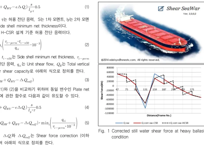
의 증/감을 결정하기 때문이다.Fig. 1은 Heavy ballast condition에서의 Corrected still water shear force를 당사에서 개발한 In-house Program을 이 용하여 계산한 결과이다. 이는 Factor
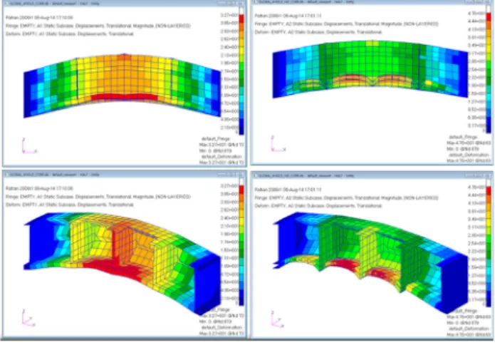
에 의한 결과 차이를 알 수가 있다.해당 부분을 Shear force correction 경향을 알아보기 위하 여 유한 요소 해석 법 (Finite Element Method, 이하 FEM)을 이용 하여 검토해보기로 하였다. FEM에 사용된 Pre/Post process는 MSC Patran, Solver는 MSC Nastran을 이용하였다. FEM에 적 용된 4 Hold model과 Boundary condition 및 Load case 는 Fig. 2~4와 같다.
Fig. 1 Corrected still water shear force at heavy ballast condition
Fig. 2 F.E model extents
Dx Dy Dz Rx Ry Rz
All longitudinal members Fix Fix Fix - - -Nodes on longitudinal memebers
at both ends of the model
Translational Rotational
Fig. 3 Boundary condition
Fig. 4 Load case
CSR-BC와 Harmonized CSR-BC의 선체 전단 응력에 대한 비교 고찰
48 대한조선학회 특별논문집 2015년 9월
Load distribution 영향을 고려하기 위하여 각 Load case에 서 Longitudinal girder 부재를 추가한 Model(LC-GF) 과 제외 한 Model(LC-F) 2가지로 나누었다.
각 Load case의 Deformation은 Fig. 5~6과 같으며, Fig.
7~8은 중립 축 부근에서의 Shear stress를 그래프로 정리하였다.
LC1의 경우 Shear stress 차이가 미비하지만 LC1-GF 의 shear stress가 BHD기준으로 증가/감소가 발생한다. 이는 Qc 가 발생됨을 알 수 있다.
Fig. 5 Deformation of LC1-GF and LC1-F
Fig. 6 Deformation of LC2-GF and LC2-F
Fig. 7 Shear stress result of LC1
LC2의 경우 Loaded hold BHD 기준으로 LC2-GF의 shear stress가 감소하였으며 이는 -Qc 이 적용하였으나, Empty hold BHD에서는 shear stress가 증가함에 따라 +Qc가 발생한 다고 볼 수 있다. 이는 Fig. 1의 H-CSR Corrected S.W.S.F 과 같은 경향을 보여준다.
아래 Fig. 9~10은 Seagoing과 Flooded condition의 Corrected S.W.S.F값을 도식화하였다. Rule 변경에 따라 Shear force값이 CSR보다 다수 증가되는 부분이 존재한다.
Shear force 증가는 Side shell thickness 증가에 영향을 끼친다.
하지만 SEAGOING에서 증가된 Shear force는 Flooded Shear
Fig. 8 Shear stress result of LC2
Fig. 9 Corrected S.W.S.F of seagoing condition
Fig. 10 Corrected S.W.S.F of flooded condition
박종민・이규호・이상복・신성광
Special Issue of SNAK, September 2015 49
force보다 적고, Flooded Shear force로 Side shell thickness 를 결정하였기에 추가적인 두께 증가는 미비하다. 하지만 Qc의 차이로 인하여 부분적으로 CSR의 Permissible shear force 보 다 높게 검토 되어야 될 필요는 있다.
3. 전단 좌굴 강도
전단 좌굴 강도(Hull girder shear buckling capacity)를 검토 하기 위한 CSR과 H-CSR의 Total vertical still water shear force는 아래의 식으로 각각 정의를 한다.
・
(8)
,
: Design still water shear force in intact condition, in KN
: Total vertical shear force, in KN (9) - For seagoing operations:
- For flooded operations at sea for BC-A and BC-B ships:
- For harbor/sheltered water operations:
식 (8)은 CSR의 좌굴 강도 검토용 Design still water shear force으로 Seagoing(Intact) condition만을 고려하지만 식 (9) H-CSR은 Seagoing / Flooded / Harbour condition 모두 고려 하도록 변경되었다.
H-CSR 설계 기준 허용 좌굴 강도는 아래의 식으로 정의를 한다.
(10)여기서 는Total shear force를 통해 구해진 Shear stress를 의미하며 허용 좌굴 강도에 비례 관계이다. CSR과 H-CSR의 전단 좌굴 강도를 비교하기 위하여 CSR의 Seagoing condition, H-CSR Seagoing condition 그리고 H-CSR Flooded condition을 비교하고자 한다. 비교하는 대상은 계산의 용이성 을 위하여 허용 좌굴 강도를 대신하여 값으로 선정하였다.
Harbour condition는
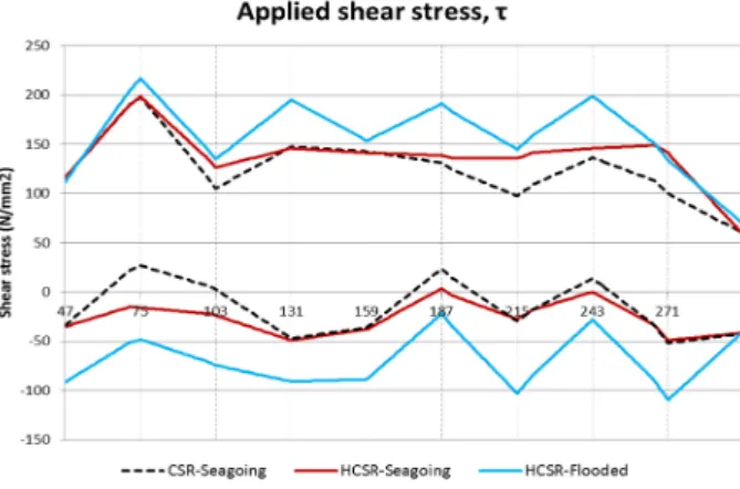
를 고려하지 않기에 비교 대상에 서 제외하였다.는 Dynamic load condition을 고려한 QTOT 을 계산하여 이를 동일한 선체 횡단면 요소의 Side shell plate의 로 Fig.
11과 같이 도출하였다.
앞서 검토하였듯이 Qc가 증가함에 따라 H-CSR Seagoing condition의 가 CSR Seagoing condition보다 큼을 알 수 있다.
또한 Flooded condition의 는 Seagoing condition에 비해 최 대 37% 큼을 알 수 있다.
Fig. 11 Applied shear stress at side shell plate
적용한 선체 횡단면 요소의 Allowable applied shear stress 가 약 190N/mm2 임을 감안하면 Rule 변경에 따라 Seagoing condition에서의 좌굴 강도에 따른 추가 보강은 거의 없다고 여겨진다. 그러나 Flooded condition을 고려함에 따라서 Shear stress가 크게 나타나는 격벽 주변부에서 추가 보강을 요하게 됨을 알 수 있다.
4. 결 론
기존 CSR에서 H-CSR로 규칙 변경에 따라 Still water shear force에서의 Corrected shear force formula는 실제 현상을 고려하 여 변경되었으나 Side shell plate thickness 증가는 미비하다. 그러 나 Corrected shear force 값이 커짐에 따라 Permissible still water shear force value는 기존 CSR보다 상승되어야 함을 알 수 있다.
좌굴 강도 측면에서는 H-CSR에서 Flooded, Harbour condition을 추가로 고려되어야 하며, Flooded condition의 전 단 응력이 Seagoing condition의 전단 응력보다 최대 30% 가 량 높아질 수 있기 때문에 Side shell plate thickness의 핵심적 인 결정요인이 될 수 있다.
본 연구에서는 Hull girder shear strength의 비교 검토를 위 하여 Local scantling 측면에서만 논의되었다. 허나 최종적으 로는 Cargo hold 구조해석을 통한 검토도 병행되어야 하며 이 는 지속 수행할 예정이다.
References
IACS, July 2008, “Common Structural Rules for Bulk Carriers”
IACS, January 2014, “Common Structural Rules for Bulk Carriers and Oil Tankers”.
박 종 민 이 규 호 이 상 복 신 성 광