반도체디스플레이기술학회지 제19권 제3호(2020년 9월)
Journal of the Semiconductor & Display Technology, Vol. 19, No. 3. September 2020.
Implementation of Non-Contact Gesture Recognition System Using Proximity-based Sensors
Kwangjae Lee
*†*†
Department of Information Security Engineering, Sangmyung University
ABSTRACT
In this paper, we propose the non-contact gesture recognition system and algorithm using proximity-based sensors.
The system uses four IR receiving photodiode embedded on a single chip and an IR LED for small area. The goal of this paper is to use the proposed algorithm to solve the problem associated with bringing the four IR receivers close to each other and to implement a gesture sensor capable of recognizing eight directional gestures from a distance of 10cm and above. The proposed system was implemented on a FPGA board using Verilog HDL with Android host board. As a result of the implementation, a 2-D swipe gesture of fingers and palms of 3cm and 15cm width was recognized, and a recognition rate of more than 97% was achieved under various conditions. The proposed system is a low-power and non-contact HMI system that recognizes a simple but accurate motion. It can be used as an auxiliary interface to use simple functions such as calls, music, and games for portable devices using batteries.
Key Words : Gesture Recognition, Motion Recognition, Proximity-based Gesture Recognition
1. Introduction
1After the success of the smart phone, a number of mobile devices operating in the battery have been developed such as smart phones, smart watches and tablet PCs. Using these devices, the studies have been performed in various fields, including health care, environmental monitoring, and user status, the gesture recognition[1-5]. Most studies are studied and developed to be applicable to a variety of environments using a combination of sensors like a touch screen, a gyro sensor, a geomagnetic and acceleration sensor, a camera and a proximity sensor. In addition, to acquire the information of the different aspects, a new type of human machine interface (HMI) has been required. A non-contact gesture recognition sensor is an HMI for providing an intuitive and natural user interfaces. And in order to apply the sensor to the mobile device, it has to meet the requirements of small size, low price, low power consumption and the like.
The non-contact gesture recognition sensors are divided
†
E-mail: [email protected]
into motion sensor-based, controller-based, vision sensor- based and proximity sensor-based system[6-9]. The motion sensor-based system is a measurement method using the inertia, such as a gyroscope or an acceleration sensor.
However, this system has the disadvantage that a high
amount of calculation required for the motion recognition
and the system requires for user always to hold the mobile
device. The controller-based system means that system is
manipulated by external controller, like wearable glove
attached multiple-sensor. This solution is expensive and
bulky for use on mobile devices. The vision sensor-based
camera system is able to detect the user motion, however,
the battery-powered devices are limited to the application,
because highly complex calculations are required. The
proximity sensor-based system has the advantage of low
power consumption and is divided into ultrasound and
infrared method[10,11]. And the mobile device uses the
infrared (IR) proximity sensor-based system, because the
ultrasonic proximity sensor-based system is a relatively
heavy and bulky. The IR proximity-based system is divided
into active and passive method depending on used parts. The
Implementation of Non-Contact Gesture Recognition System Using Proximity-based Sensors 107
passive type measures the far-infrared rats generated in particular hand of user, thus this type is possible to implement low-power system because it consists of optical infrared receiving elements, photodiode (PD) only. Because the pyroelectric PDs for measuring the far-infrared rays are sensitive to environmental changes, the recognition rate is significantly low, about 70%. Whereas the active type uses IR LED to the emitter, it has a recognition rate of 90% or more in a variety of applications. In an active system, IR LED emits IR ray and then PD receives reflected IR back from the object. This method measures the signal intensity from the distance between the object and the sensor, and it recognizes the various operations by changing the signal intensity. In almost cases, the system consists of one IR LED and a plurality of PD, because IR LED is the most power consuming device. But this system has disadvantage that the less distance it becomes, the lower recognition rate it has. Thus, it could not be made small to be applied to the mobile device. In previous studies, in order to maintain the recognition rate while reducing distance between PDs, we have developed a sensor with a small form factor by limiting the optical path of the PD.
As a result of the implementation, a 2-D swipe gesture of fingers and palms of 3cm and 15cm width was recognized, and a recognition rate of more than 97% was achieved under various conditions. The proposed system is a low-power and non-contact HMI system that recognizes a simple but accurate motion. It can be used as an auxiliary interface to
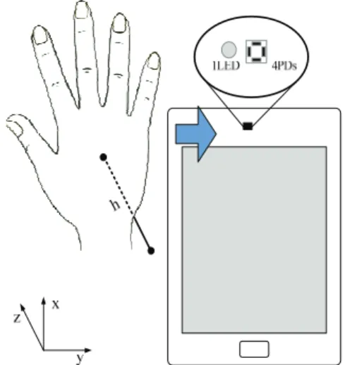
Fig. 1. The proposed non-contact gesture recognition sensor system.
use simple functions such as calls, music, and games for portable devices using batteries.
2. Architecture of the Proposed Gesture Recognition System
2.1 Concepts
A Proposed recognition system is proximity-based sensing. Four PDs receive the signal emitted from the IR LED and reflected on close object and the recognition algorithm determines the direction using the difference in the signal levels produced by a distance close object and the spatial difference of the respective PDs. Fig. 2. represents the time response characteristics of the signal received in the PDs when object is moving. Among them, Fig. 2. (a)-(c) show the received signal intensity from the PDs depending on the time t1-t3 when the object is moving to the right and Fig. 2. (d) represents received signal intensity for the previously described diagram, where a black dotted line is the infrared signal from IR LED, and a blue dotted line is the view angle of the PD. When an object is approaching from one side toward the sensor, the reflection signal comes in the view field of the PD more. Accordingly, it is possible to determine the relative distance to the object and the sensor.
Thus, Fig. 2. (d) shows the signal change means that an object is moving from left to right.
In other words, if the recognition system receives a signal
Fig. 2. The variation of received signal intensity on a PD
according to object movement. (A black dotted line
means the light from IR LED and a blue dotted line
means viewing angle of the PD.)
Kwangjae Lee 108
intensity of a plurality of PDs arranged in a particular position instead of a single PD, received signals of the PDs have different signal characteristics, depending on the spatial distance of the PD. And this signal difference can be utilized as information to estimate the direction of the object.
However, if the spatial distance between the PDs is small, the gesture recognition rate is lower.
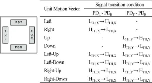
Thus the recognition system is impossible to implement a small form factor because the received signals of the PDs are almost similar characteristics. A sensor used in the proposed system is composed of four PDs where are placed in top, bottom, left, and right, as shown in Fig. 3. And the PDs are designed a rectangle shape to increase the direction selectivity of the sensor. In addition, the proposed system uses sensors that has package able to reliably distinguish each signal intensity of PD even the distance of PDs gets narrow in order to be applied to mobile devices. In the following, the optical structure and its decision method of the system for non-contact operation recognition is described. The proposed scheme recognizes the movement of top, bottom, left, right and diagonal in the air.
Fig. 3. The structure of a PD module and functional table for corresponding unit motion vectors.
2.2 Optical Structure
Gesture recognition sensors for mobile devices have a small form factor, several mm and also, in the proposed structure, the single integrated chip, the distance between PDs should design about 1-2mm. However, the conventional systems having a high recognition rate of 90%
or more is implemented in significantly large distance between PDs, several cm and more. If reducing the distance between the PDs from few cm to few mm, the recognition rate drops rapidly. The proposed structure controls optical paths to the asymmetry view angle of PDs through the
package maintaining a high recognition rate, and to reduce the sensor size Fig. 4. (a)-(b) represent a sensor structure and signal response characteristics of the conventional system.
For simplicity, the figure shows an example of the x-axis.
Fig. 4(a) shows the structure of the PDs in the x-axis and PD
Land PD
Rare placed a predetermined spacing for gesture recognition and Fig. 4(b) shows a time response of PDs when the object moves from left to right at a constant speed where t1 and t2 refers to the time when the object to be located on the center of PD
Land PD
R, respectively. PD
Lincreases the signal intensity slowly, after being saturated, decrease back slowly. And PD
Rmoves followed the PD
Lbecause PD
Lis spatially to the left than the PD
R. Also, since the photodiodes have a wide viewing angle over 175 degrees made from semiconductor processes, and a photodiode covers very wide scope. This conventional system occurs a malfunction due to noise in the surrounding environment or device because the system should recognize to use a few time difference. If there has to correct this problem, a number of resources are used as well as the sensor have slow response.
The proposed optical structure is designed to have an asymmetric viewing angle by limiting the wide viewing angle of PDs and this structure improves the problem of the low signal and time margin of the conventional structure.
Fig. 4. (c)-(d) represent a sensor structure and signal response characteristics of the proposed system. For simplicity, the figure shows an example of the x-axis. A partially open cavity package makes a photodiode with an asymmetric viewing angle to control forces in the optical path through the optical block. As shown in Fig. 4.(c), the PDs have an asymmetrical viewing angle and PD
Land PD
Ris symmetrical and Fig. 4.(d) shows a time response of PDs when the object moves from left to right at a constant speed where t1 and t2 refers to the time when the object to be located on the center of PD
Land PD
R, respectively. If the object is on the left and move right at a same speed, the signal intensity of PD
Rgradually increases, unlike the conventional structure, while the signal intensity of PD
Lincreases rapidly approaching at time t1. After time t2, the signal intensity of PD
Lgradually decreases, and the signal intensity of the PD
Rrapidly decreases and then, the signal disappears as a PD
R, PD
Lorder. A signal and timing margin of this structure are sufficiently larger than the previous system. Thus, it is suitable for non-contact motion
Unit Motion Vector Signal transition condition PDL- PDR PDT- PDB
Left LTH,X→ HTH,X -
Right HTH,X→ LTH,X -
Up - LTH,Y→ HTH,Y
Down - HTH,Y→ LTH,Y
Left-Up LTH,X→ HTH,X LTH,Y→ HTH,Y Left-Down LTH,X→ HTH,X HTH,Y→ LTH,Y Right-Up HTH,X→ LTH,X LTH,Y→ HTH,Y Right-Down HTH,X→ LTH,X HTH,Y→ LTH,Y
Implementation of Non-Contact Gesture Recognition System Using Proximity-based Sensors 109
Fig. 4. Optical structures and its time response character- istic of the gesture sensor for signal intensity of two PDs in case of x-axis.
recognition sensor system for mobile devices that require smaller form factor.
2.3 Motion Detection Method
The gesture recognition system for mobile devices has a noise problem which input of PDs are influenced by the surrounding environment and large changes of internal signal because of a small form factor. If the noise external impulse noise at the same time and also minimizes the AC coupling due to a large signal change such as LED Driver.
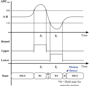
Fig. 5. illustrates an example of the motion decision method by using a differential signal. If the objects move to the right, a PD signal ‘A’ reacts first and then a PD signal ‘B’ reacts following. A-B is expressed as shown in the graph of ADC
OUTand the ADC value is converted to the 1-bit
Fig. 5. A block diagram of the proposed 4-ch gesture recognition system.
threshold signal based on high and low threshold. In a state section, a decision algorithm recognizes the movement using the converted signal transition where a signal ‘H’
denotes the wait period for other axial direction to recognize diagonal direction.
Fig. 6. An example of the proposed decision method for non-contact gesture recognition sensor system.
Even if the differential signaling method is used, white
noise that changes at random cannot be reduced. However,
since Spectrum Power Density(SPD) of white noise is '0',
the noise can be reduced by averaging for a certain period of
time. Average Filter(AF) is the most common white noise
canceling method, but has a disadvantage in not recognizing
fast gestures due to its slow response speed. To compensate
for this, a Moving Average Filter(MAF) can be considered,
but in this system, the amplifier's amplification factor is very
high to increase the sensitivity, so the deviation of each
sample is severe[12]. In this case, the Moving Average Filter
method is not accurate. Therefore, in this paper, the Median
Filter(MF) method was used. Even if the deviation is severe,
there is no additional effort because the intermediate value is
used, and the window is small, so a fast reaction speed can
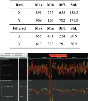
be obtained. Table 1 shows the statistics before/after
applying filtering, and Fig. 7 shows the simulation using
actual sensor input. When filtering is applied, the deviation
is reduced to 15% compared to the original, and the
response rate is 17.5ms (5 samples).
Kwangjae Lee 110
Table 1. Signal data statistics before/after applying the Median Filter
Fig. 7. A filter simulation using real measured data.
3. Experimental Results
The test environment consists of a gesture recognition sensor, a recognition processor and a smartphone for motion recognition as shown in Fig. 6. The gesture recognition sensor is a single module which compose of one IR LED and four PDs and the gesture processor is implemented to FPGA board using Verilog HDL with Android host board.
An LCD of android host board is used as a gesture display.
The output motion vector of the gesture, according to the movement of the hand as an example of the gesture recognition experiment.
Verification of the proposed system is required to measure recognized distance of a variety of objects in the air because the system receives reflected infrared signals from the object.
The gesture recognition experiments were tested in a position 10cm apart from the sensor, using 3cm and 15cm width of white objects, finger and palm and the proposed system obtained more than 97% recognition rate under various conditions. Among experimental results, the palm case was lower recognition rate because the light is diffusely reflected on a bumpy surface.
Fig. 8. The proposed proximity-based sensor and a test environment of the proposed non-contact gesture recognition system.
Fig. 9. Example of test sequence, left-down swipe.
In addition, since the light reflectivity varies depending on the color, the recognition distance varies depending on object color. Thus, an experiment was conducted in a variety of colors, and the results are shown in Table 2. Experimental results show that the recognized distance is affect by reflection rate and even black color could recognize more than 10cm. Although we conducted experiments depending on a variety of color, there were no significant differences, except for brightness.
Table 2. Test results of operated distance between the sensor and object for the corresponding reflection rate Color Contrast Rate Operation Rage (cm)
90% 20.75
80% 19.00
60% 18.25
50% 17.00
40% 15.25
30% 15.00
10% 14.25
0% (Black) 10.50
Raw Max Min Diff. Std.
X Y
891 908
227 126
655 782
138.2 171.8 Filtered Max Min Diff. Std.
X Y
655 613
431 322
224 291
20.9 30.5
Android Host Board FPGA Board
Gesture Recognition Sensor
Display Module
Host I/F
Implementation of Non-Contact Gesture Recognition System Using Proximity-based Sensors 111