Design of a Bimorph Piezoelectric Energy Harvester for Railway Monitoring
Jingcheng Li*, Shinae Jang*
✝and Jiong Tang**
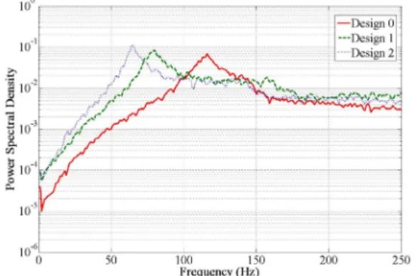
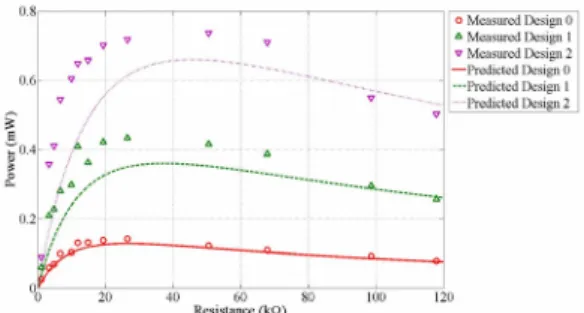
Abstract Wireless sensor network is one of prospective methods for railway monitoring due to the long-term operation and low-maintenance performances. How to supply power to the wireless sensor nodes has drawn much attention recently. In railway monitoring, the idea of converting ambient vibration energy from vibration of railway track induced by passing trains to electric energy has made it a potential way for powering the wireless sensor nodes. In this paper, a bimorph cantilever piezoelectric energy harvester was designed based on a single degree-of-freedom model. Experimental test was also performed to validate the design. The first natural frequency of the bimorph piezoelectric energy harvester was decreased from 117.1 Hz to 65.2 Hz by adding 4 gram tip mass to the free end of the 8.6 gram energy harvester. In addition, the power generation of the piezoelectric energy harvester with 4 gram tip mass at resonant frequency was increased from 0.14 mW to 0.74 mW from 2.06 m/s
2base excitation compared to stand-alone piezoelectric energy harvester without tip mass.
Keywords: Piezoelectric, Energy Harvesting, Railway, Structural Health Monitoring
[Received: November 1, 2012, Revised: November 23, 2012, Accepted: November 26, 2012] *Civil and Environmental Engineering Department, University of Connecticut, Storrs, CT 06269, U.S., **Mechanical Engineering Department, University of Connecticut, Storrs, CT 06269, U.S. ✝ Corresponding Author, Email: [email protected]
ⓒ 2012, Korean Society for Nondestructive Testing
1. Introduction
Wireless smart sensors have drawn significant attention in general structural health monitoring realm in recent years due to its wireless, low cost, and versatility. Especially, wireless sensor network with self-powered ability have been of increasingly interests for the rails with high demand in railway monitoring under natural and manmade disasters. In general, energy generated from ambient environment such as solar power, wind energy, vibration energy, etc., can be stored in energy storage devices to provide power for the wireless sensors. By powering these wireless sensors from ambient energy, the performance of the sensor networks will be improved and the maintenance costs will be reduced [1]. In railway monitoring, the vibration energy from railway track induced by passing train is a large amount energy which can be used for powering wireless sensors.
Electromagnetic, electrostatic and piezoelectric are the most commonly used energy harvesting mechanisms for converting vibration energy to electric energy [2]. The comparison of these three mechanisms for microsystem has been summarized by Beeby et al. [3]. While each type of these three mechanisms has its benefits for certain applications, it appears that piezoelectric energy harvesters are capable for generating electric power from vibration energy for wireless sensor nodes since recent studies show wireless sensors used for railway monitoring requiring as low as a few mW [4].
As the development of piezoelectric energy
harvesting, a cantilever beam with piezoelectric
material attached to the top and bottom surfaces
becomes an attractive structure for harvesting
energy from ambient excitation. Glynne-Jones et
al. [5] investigated the power output of a
generator fabricated by piezoelectric materials
attached to the top and bottom of a 0.1 mm
stainless steel beam, a maximum power of 3.3 µW was generated under a frequency of 80.1 Hz with optimal resistive load of 333 kΩ.
Similar study has been performed in the work of duToit et al. [6] for validating the mathematical model. However, a maximum power of 586 µW was measured with 2.5 m/s 2 base acceleration at resonant frequency. Similar results can also be found in Erturk and Inman’s work [7]. In addition, a bimorph piezoelectric cantilever beam generator with proof mass on the free end was developed by Roundy et al. [8, 9]. Proof mass on the free end significantly increase the power output of the piezoelectric cantilever beam. A maximum power output of nearly 80 µW with a power density of 70 µW/cm 3 was produced with a 250 kΩ load resistor, at 2.5 m/s 2 input acceleration and resonant frequency of 120 Hz. After optimal design, the power density could be improved to be 250 µW/cm 3 from a vibration source of 2.5 m/s 2 at 120 Hz. On the other hand, in railway monitoring, the first resonant frequency of a cantilever beam structure can be easily tuned to be close to the excitation frequency from the passing train, which means that the cantilever beam structure can be excited around resonant frequency at most of time to get the maximum power output. In addition, the first resonant frequency of the cantilever beam structure can be further reduced by the addition of a tip mass. Those reasons above make the cantilever piezoelectric energy harvester one of potential solutions to long-term, low maintenance power supply for distributed wireless sensor nodes.
In order to design an efficient cantilever piezoelectric energy harvester from the excitation of railway track induced by passing train, the characteristics of the railway track vibration should be considered regarding to the dominant vibration frequency. The main mechanisms of railway vibration arise from dynamic forces at wheel/rail, and rail/ground interfaces. The wheel/
rail interface refers to rail vibration under moving wheel, and wheel/rail unevenness, while the rail/ground interface refers to the ground- borne vibration [10,11]. Many factors influence the vibration of railway track including train speed, length of rail car, rail and wheel roughness and material properties of the foundation et al.. An experimental test was carried out by Chatterjee et al. [12] for determining the track responses during the passage of trains at variable speeds. A dominant rail vibration frequency less than 5 Hz can be found in each train speed which was contributed by the passage of all axles and bogies. On the other hand, a dominant rail vibration frequency range between 20 Hz and 80 Hz can also be found which was caused by the wheel and rail roughness at variable train speeds. Similar results were also presented by Degrande et al. [13]. To date, most energy harvesters employed to harvest energy from vibrations or vibration structures are operated in resonance at single excitation frequency. However, in railway monitoring, the dominant rail excitation frequency is a range rather than a single excitation frequency which requires the energy harvester can be worked in a broad frequency range. In order to design such an energy harvester, the first step will be designing an energy harvester whose resonant frequency will be within the rail excitation frequency range, and the second step is to broaden the working frequency.
In this paper, a cantilever bimorph
piezoelectric energy harvester with tip mass
whose resonant frequency is between 20 Hz and
80 Hz is designed based on a single degree-
of-freedom model for simplicity. The feasibility
of the single degree-of-freedom model is
validated from experimental tests. In addition,
the effect of the tip mass of the piezoelectric
energy harvester is investigated on natural
frequency modification to maximize power
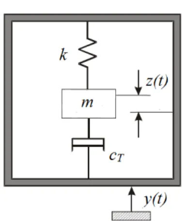
Fig. 1 Single degree-of-freedom model
(a) Piezoelectric without tip mass
(b) Piezoelectric with tip mass
Fig. 2 Schematic of a bimorph piezoelectric energy harvester with and without tip mass in series connection
generation. Based on the theoretical and experimental results, further work in widening the working frequency of the harvester will be performed in future.
2. Mathematical Model
A simple single degree-of-freedom (lumped parameter) model is used in this paper for simplicity (The limitations of the single degree- of-freedom model have been discussed by Erturk and Inman [14]). Fig. 1 shows the schematic of such a system where m is the system mass, k is the spring of stiffness, and c T is the total damping coefficient. The system is being excited by an external sinusoidal vibration y(t) = Ysin(ω t) (where Y is the amplitude of the acceleration and ω is the vibration frequency), resulting in the mass moves as z(t). The equation of motion of the system is described in Eq. (1).
( )
T( ) ( ) ( )
mz t && + c z t & + kz t = − && my t (1)
Since energy is extracted from relative movement between the mass and the base, the maximum power is generated when the excitation frequency matches the natural frequency of the system ω
n= k m / . And total damping ratio (ζ t = k/2mω n ) prevents the power goes to infinity when the generator vibrates at resonant frequency.
Fig. 2 shows the schematic of a bimorph piezoelectric energy harvester with and without tip mass in series connection. It can convert the vibration energy to electric energy.
Based on Challa’s work [15], the open voltage V 0 generated from the system depends on the stress σ developed in the structure and the material properties of the piezoelectric patch, as shown in Eq. (2):
31 0
p n
V d t σ ε
= − (2)
where t p is the thickness of the piezoelectric layer, -d 31 is the piezoelectric strain constant, and ε is the dielectric constant of the piezoelectric material, and σ n is the piezoelectric stress at resonant frequency:
2 2
3
n
4
t n
EYh σ L
= ζ ω (3)
where E is the effective modulus of the beam, h is the distance of the piezoelectric layer from the neutral axis, L is the length of the beam.
n
k
eff/ m
effω = , k eff = 3EI/L 3 , m eff = 33m b /140+m t ,
m b is the total mass of the beam, and mt is the
tip mass. The damping ratio can be obtained by
Property Symbol Values Property Symbol Values
Length (mm) L 50.8 Brass modulus (GPa) E
s105
Width (mm) b 31.8 Piezo modulus (GPa) E
p66
Brass thickness (mm) t
s0.14 Tip mass (kg) M
t0.002(each)
Piezo thickness (mm) t
p0.26(each) Piezo dielectric constant (F/m)
33ε
S1500ε
0Brass density (kg/m
3) ρs 9000 Piezo strain constant (pm/V) d
31-190 Piezo density (kg/m
3) ρ
p7800
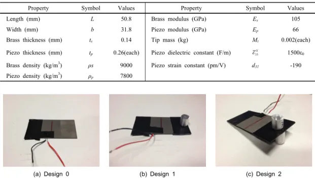
Table 1 Geometry and material properties of the piezoelectric energy harvester
(a) Design 0 (b) Design 1 (c) Design 2
Fig. 3 Piezoelectric energy harvester prototype a) design 0 without tip mass b) design 1 with one tip mass c) design 2 with two tip mass
performing a flick test, through which an amplitude decay plot is obtained and the corresponding damping is determined by:
1 2
1 2
In a ζ a
= π (4)
The power generated from the piezoelectric energy harvester can be calculated such that:
2 0
( )
2Lp p
s Lp