Improvement of Form Accuracy of Micro-Features on Thin, Large-area Plate using Fast Depth Adjustment in Micro-grooving
Dong Bae Kang
a, Seong Min Son
b, Hyo Ryeol Lee
a*, Jung Hwan Ahn
c대면적 가공물의 마이크로 그루빙에서 고속 절삭 깊이 제어를 통한 미세형상의 정밀도 향상
강동배
a, 손성민
b, 이효렬
a*, 안중환
ca
Intelligent Control and Automation in the School of Mechanical Engineering, Pusan National University, Republic of Korea
b
School of Digital Mechanics, Ulsan College, 57 Daehak-ro, Nam-gu, Ulsan 680-749, Republic of Korea
c
School of Mechanical Engineering, Pusan National University and ERC/NSDM, Republic of Korea
ARTICLE INFO ABSTRACT
Article history: Micro-features such as grooves and lenses, which perform optical functions in flat displays, should be manufactured with a good form accuracy because this is directly related to their optical performance. As the size of the display increases, it is very difficult to maintain a high relative accuracy because of the inherent geometric errors such as the waviness of a large-area plate.
In this paper, the optical effect of these geometric errors is investigated, and surface-referenced micro-grooving to measure and compensate for such geometric errors on line is proposed to improve the form accuracy of the micro-grooves. A PZT-based fast depth adjustment servo system is implemented in the tool holder to maintain a uniform groove depth in reference to the wavy surface. Through experiments, the proposed method is shown to be an efficient way to produce high-quality micro- grooves on a wavy die surface.
Received 4 April 2013
Revised 8 May 2013
Accepted 8 May 2013
Keywords:
Form accuracy Micro grooves
Fast depth adjustment servo system Surface - referenced grooving
* Corresponding author. Tel.: +82-51-510-3087 Fax: +82-51-581-3087
E-mail address: [email protected] (Hyo Ryeol Lee).
1. Introduction
With the growing need for human visual satisfaction, the flat display is getting larger and many technical advances, not only in design but also in manufacturing, have been achieved to improve the optical performance of the display. In manu- facturing, it is a great technical challenge to maintain within a certain level the form accuracy of the micro-features on a large flat display because a larger flat plate would inherently
have larger geometric errors, such as waviness and warping.
For example, the light guide plate (LGP) of the back light unit
(BLU), which is a component of a Liquid Crystal Display
(LCD), has an important role in scattering the incident light
over the whole display area. To uniformly scatter the light,
a lot of micro-grooves of a long prismatic shape are formed
on a polymethyl-methacrylate (PMMA) surface through
injection molding or micro-grooving. In the case of injection
molding, which is the most popular for the mass-production
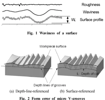
Fig. 1 Waviness of a surface
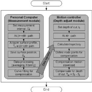
(a) Depth-line-referenced (b) Surface-referenced Fig. 2 Form error of micro V-grooves of flat displays, lots of micro-grooves are machined on the flat
die surface through the micro-grooving process in a precision machine tool. Especially for the larger LCDs, micro-grooving can achieve more uniform optical characteristics because the micro-grooves that are produced by micro-grooving are more accurate than those produced by injection molding, which may cause thermal deformation.
Even if either a die or a PMMA plate is machined even in a perfectly stiff and accurate machine tool, the form accuracy of the finally machined micro-grooves is determined by geometric errors such as waviness and warping. Actually, as a plate becomes thinner and larger, the geometric error becomes much greater due to warping even through small, external fixing forces; this results in quite a big form error, which in turn causes non-uniform, light-scattering pattern.
Here, we suggest a new method to make uniform micro-grooves even on a plate with a big form error, i.e., a surface-referenced micro-grooving, instead of intentionally flattening a wavy surface prior to micro-grooving on the plate. To implement surface-referenced micro-grooving a method for the real-time measurement of and compensation for the waviness is required to maintain the micro-groove form accuracy over the whole plate within a tolerance level throughout the entire machining process.
A few methods for the measurement of and compensation for geometric errors have been proposed to improve the machining accuracy
[1-2]. Some studies are focused on compensating for machine-tool errors themselves. To compensate for such errors, a Fast Tool Servo (FTS) or dual servo that is combined with FTS has been widely used. Kohno et al. suggested a method called WORFAC (Workpiece-referred form accuracy control system) to straighten a cylindrical surface during ultra- precision turning
[3].
In this study, the effect of the micro-groove form error on the light scattering performance is investigated through optical simulation. Then, the surface-referenced micro-grooving system, which consists of on-line geometric error measurement and compensation units, is developed. Its feasibility is examined through application to PMMA plates.
2. The effect of micro-groove form accuracy on optical performance
2.1 The form error of micro-grooves on a wavy surface In general, the profile of an even flat surface has a relatively low frequency wave, and a higher frequency roughness, as shown in Fig. 1.
Moreover, when a flat surface is fixed on a table for machining, warping by the fixing force is added to the surface profile. If micro-grooves are machined on such a surface with no consideration of waviness, the groove depth deviates quite a lot along the warped wavy surface, as shown in Fig. 2(a).
In fact, the depth and the width of micro-grooves that are widely used in flat displays are several tens of mm, while the waviness ranges from a few tens to hundreds of mm, as the display area increases. The micro-groove form error that is caused by waviness and warping is assumed to worsen the optical performance of displays, e.g., the uniformity of light scattering
[4].
To solve this problem regardless of the plate surface conditions such as waviness and warping, it is necessary to develop methods for making micro-grooves of constant depth along even a wavy surface, as depicted in Fig. 2(b).
2.2 Optical simulation
In a BLU, as shown in Fig. 3, the LGP reflects the light
Fig. 3 Light scattering by a LGP in the Back Light Unit
(a) 5 mm (b) 2 mm (c) 0.5 mm Fig. 4 Optical characteristics at various form errors (for a 10 mm
V-groove)
Fig. 5 Concept of surface-referenced micro-grooving
Fig. 6 Flowchart for fast depth adjustment that comes from both the Cold Cathode Fluorescent Lamp
(CCFL) and the reflector and the reflected light goes out due to micro-groove patterns on the back surface of the LGP.
To examine the effect of micro-groove form accuracy on the light scattering characteristics in a BLU, a simulation has been conducted with the simulation software, SPEOS of OPTIS Co.
Ltd.
Under assumption of a simplified form error, that is, groove depth deviation that is due to the waviness of the V-groove with a depth of 10 mm, three cases of form error (5, 2 and 0.5 mm), which represent the relative form accuracy of 50%, 20%, and 5%, respectively, are studied. Irradiances are measured vertically along the two lines, A and B, as depicted in the simulation results.
As shown in Fig. 4, the uniformity of optical scattering improves as the form error reduces. For the cases of 5 mm and 2 mm, the uniformity deviation can be clearly seen in both surface and irradiance sensing lines.
From this result, it is clear that the form accuracy of micro- groove patterns should be kept at least below 5% for good optical uniformity.
3. Surface-referenced micro grooving system
3.1 Constant-depth trajectory generation
Fig. 5 illustrates the concept of the proposed surface-referenced micro-grooving system that is composed of an on-line surface profile measurement module and a fast depth-adjustment module. The laser displacement sensor is attached at a distance -as much as Dvs-T-from the tool.
Fig. 6 shows the procedures of two simultaneous modules
for depth adjustment: on-line surface profile measurement and
compensated depth control. The on-line measurement module,
which includes surface profile measurement, noise filtering,
and surface modeling, is processed by a PC, whereas the
depth compensation module, including the depth trajectory
Table 1 Specifications for fast depth adjustment system Actuator PZT - 1 5 ㎛ (open-loop)
Guide Leaf spring hinge
Feedback sensor Micro linear scale Resolution [nm] / linearity [nm] 5 / 50
Displacement sensor / Resolution [nm]
Laser displaement sensor / 50
Fig. 7 Micro-grooving machine tool with FTS
Fig. 8 Sinusodal responses of fast depth adjustment system (Amplitude: 100 ㎛, frequency 5 Hz)
calculation and the dual servo control, is executed by a motion controller, PMAC.
During actual cutting, the laser displacement sensor measures the height profile of each line on the surface Dvs-T ahead of the current cut-path. From the measured surface profile data, the waviness of the next cut-path can be interpolated. Through referencing to the interpolated surface profile, the depth commands along with the next cut-path are calculated prior to the actual cutting.
3.2 Fast depth adjustment servo system
Fig. 7 shows a schematic diagram for the micro-grooving machine tool with a fast tool servo that is developed in this study. The machine tool is composed of three axes, X, Y, and Z. The X-axis is guided by an air bearing with negligible friction and driven by a coreless linear motor. The Y and Z axes are actuated by core linear motors with a resolution of 0.1 ㎛. The effect of the motion error on the micro-groove form error is negligible because the straightness of the air bearing is below 0.1 ㎛.
The fast depth-adjustment module is composed of a linear motor for coarse motion and a PZT actuator for fine motion.
When a compensated depth command is given to the fast
depth-adjustment system at a control interval, the z-axis linear motor immediately responds to the instant step input. At the same time the error between the previous command and the actual linear motor movement is input to the PZT servo system for completely making up for the error. That scheme of dual servo system was proved to track very well a desired depth trajectory because of the PZT’s higher response
[5,6].
The PZT actuator has the dynamic characteristics; the following error of below 0.1 ㎛ for a 5 ㎛ sinusoidal input and the settling time of about 3 msec for a 5 ㎛ step input.
Fig. 8 shows the dynamic performance and accuracy characteristics of the fast depth adjustment system for a 10-Hz sinusoidal input with a 100 ㎛ amplitude. The linear motor traces the waviness pattern with the tracking errors up to 4
㎛, which is narrowed down to 0.3 ㎛ by the PZT actuator.
Table 1 shows the specifications of the fast depth adjustment system developed in this study.
4. Experiments on surface-referenced micro-grooving
4.1 Die surface profile
Fig. 9 shows the surface profile measurement results of an Al6061 die plate used in the real cutting. Due to waviness, quite large errors up to 40 ㎛ are seen.
4.2 Results of micro-grooving
Fig. 10 shows the results of depth adjustment in the actual
Fig. 9 3D surface profile of an Al6061 die plate
Fig. 10 Response of depth adjustment during actual micro-grooving
(a) 2D Cross-sectional view on path P-P’
(b) 2D Cross-sectional view on path Q-Q’
(c) 3D on path Q-Q’
Fig. 11 Form error comparisons of micro grooves micro-grooving on the wavy die surface. The interpolated
waviness of the cut-path A-A’ on the surface is about 40 ㎛ in the amplitude over the span of 180 mm.
The tracking errors are -1 ~1 ㎛ after the Z-axis linear motor compensation and the final errors from the desired path after the PZT compensation are below 0.3 ㎛. It is expected that the form errors due to waviness are successfully compensated within relative accuracy of 1% with the fast depth adjustment.
Fig. 11 shows the comparison of the form errors of micro grooves which are machined on the cut-path, A-A’ with the fast depth adjustment and on the cut-path, B-B’ without the fast depth adjustment.
Fig. 11(a), (b) show the cross-sectional measurements of the micro-grooves on the two cut-paths A-A’, B-B’ along the measurement paths P-P’ and Q-Q’.
Fig. 11(c) shows the three dimensional view around two micro grooves modelled by the measurement data.
Through the surface-referenced micro-grooving with the fast depth adjustment algorithm, uniform micro grooves can be formed even on a wavy surface.
5. Conclusions
In this paper, the importance of the form accuracy of the micro-grooves on a thin large-area plate is ascertained and a new method called the surface-referenced micro-grooving is proposed. Furthermore a system that consists of an on-line surface measurement module and a fast depth adjustment servo module is developed and its validity is confirmed through experiments. The conclusions are as follows:
(1) The form accuracy of a micro-feature based optic device is a major factor for its functioning as desired.
(2) The surface-referenced micro-grooving system is an
efficient way to obtain uniform micro-grooves even on a
wavy plate.
(3) Using the fast depth adjustment servo system using a PZT actuator, the form error as much as 40 ㎛ is greatly reduced to less than 1 ㎛.
Acknowledgment
This work was supported by a 2-year Research Grant of Pusan National University.
References