Journal of Welding and Joining, Vol.35 No.1(2017) pp49-54 1. Introduction
Nickel-based super-alloys comprise a considerable proportion of researches in aerospace industries. The corrosion and creep resistance properties associated with these alloys has made them fundamental materials for motor parts in hot sections such as turbine disks and fins. In such applications, assembly of various parts tak- ing advantage of welding constitutes a significant stage in design and manufacture of these products. Therefore, weldability study of such materials is of foremost im- portance. Owing to some properties attributed to these materials, welding technologies with high power den- sities, especially electron beam welding (EBW), are applied. As a matter of fact, this welding technology en- tails the smallest fusion zone and heat effected zone, and this fact leads to reduction of distortions and re- sidual stresses. Nevertheless, presence of residual stresses in critical parts can decrease their life and strength.
Owing to the critical applications of electron beam welding, many researches in the past years have fo- cused on this welding process. In 2001, Koleva
1)con-
ducted a statistical mult-response study on electron beam welding of stainless steel samples in order to opti- mize the process. Zhu et al.
2)in 2002 studied the effect of temperature-dependent material properties on weld- ments through 3D nonlinear analysis of welding taking advantage of finite element method. In 2003, Couedel et al.
3)modeled a moving heat source through 2D finite element modeling. Ferro et al
4)in 2004 carried out a nu- merical and experimental research on plates made from the nickel-based super-alloy of Inconel 706 in order to study the effect of electron beam welding parameters on geometrical and microstructural properties. In the same year, Ram et al
5)presented design of experiments and parameter optimization in electron beam welding mak- ing use of variance analysis. In 2005, Ho
6)analytically studied the effects of conical specifications of the elec- tron beam on the fusion zone. The same author in 2007 in another paper
7)proposed an analytical 3D solution for prediction of temperatures in the welding pool of electron beam welding. One year later, Zhao et al.
8)studied residual stress and distortion reductions in elec- tron beam welding taking advantage of multiple beams technique, and investigated the topic through finite ele-
H eat Source Modeling and Study on the Effect of Thickness on Residual Stress Distribution in Electron Beam Welding
Leila Rajabi*
,†and Majid Ghoreishi**
*Dept. Of Mechanical Engineering, KN Toosi University of Technology, Tehran 19991_4334, Iran
**Faculty of Mechanical Engineering, KN Toosi University of Technology, Tehran 19991_4334, Iran
†Corresponding author : [email protected]
(Received August 23, 2016 ; Revised October 10, 2016 ; Accepted October 19, 2016)
Abstract
In this study, the volumetric heat source in electron beam welding (EBW) is modeled through finite element method taking advantage of ABAQUS software package. Since this welding method is being applied in plates with different thicknesses and also considering that residual stresses reduce the strength of these weldments, the effect of thickness in the distribution and magnitude of residual stresses after welding is studied. Regarding the vast application of Inconel 706 super-alloy in aerospace industries, this material was selected in the current research. In order to validate the finite element model, the obtained results were compared to those of other researchers in this area, and good agreement was observed. The simulation results revealed that increase in the plate thickness leads to increase in the residual stresses. In addition heat treatment in the base metal (before welding) increases the residual stresses significantly.
Key Words : Electron-beam welding, Finite element modeling, Inconel 706, Residual stresses, Thickness
ISSN 2466-2232
Online ISSN 2466-2100
ment analysis and experimental studies. In the same year Qi et al.
9)took advantage of high energy density, high absorption rate and vacuum environment of elec- tron beam technology in Electron beam selective melt- ing316 stainless steel powders. In 2009, Luo et al.
10)si- mulated the thermal effect of electron beam welding in a magnesium alloy through 3D modeling of the heat source in vacuum. Liu et al.
11)in 2011 studied variation of welding residual stresses after material removal from a 50 mm thick plate of a titanium alloy welded through electron beam welding. In a recent study in 2011, Jha et al.
12)conducted different experiments on 304 stainless steel plates in order to control welding outputs in terms of yield strength and ultimate tensile strength through monitoring input parameters namely accelerating volt- age, beam current, and welding speed. They took ad- vantage of neural networks in their optimization.
In this study, Finite element simulation is utilized to model the welding process and predict the consequent residual stresses. Here, ABAQUS software package was employed to conduct finite element modeling, and the results obtained were compared to those in
4), in or- der to validate the model. The agreement observed be- tween the results provided confidence in the validity of the model.
2. Heat Source Model For EBW
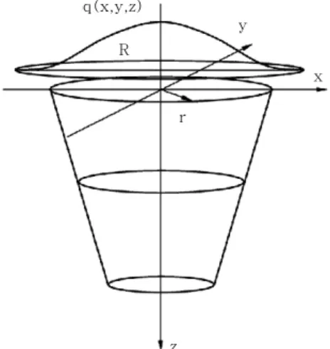
Fig. 1 illustrates the combined heat source model ap- plied in this study. The effect of heat diffusion asso- ciated with the keyhole is simulated through a three-di- mensional conical heat source model. In other words, the metal vapor with a temperature higher than boiling point with local thermodynamic equilibrium bears the same properties as a surface heat source. A Gaussian surface heat source model is applied to simulate the sur- face thermal effects.
The distribution of the heat flux associated with the surface source is as below:
× exp
(1)
(2)
(3)
where V denotes voltage, I is amperage, V
1denotes the volume of the spherical heat source, and R represents the effective radius of the electron beam. According to the rotating body property, x
2+y
2=r
2, where r is the radi- al distance of each point in the heat source from the center.
When the welding heat source moves on, the inlet heat flux alters in the different positions throughout the welding path. Thus, the moving coordinates and the sta- tionary ones are related as:
(4)
where t is the welding period, and υ is the welding speed. After transformation between stationary and moving coordinates, Equation (1) is modified into Equation (5):
× exp
(5)
where x
2+u
2=r
2.
The distribution of the heat flux associated with the conical heat source is according to the following:
× exp
(6)
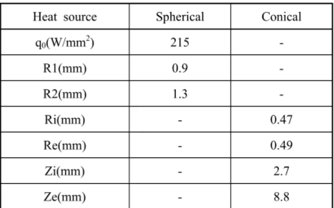
(7) where V is the voltage, I represents the amperage, and V
2denotes the volume of the conical heat source. The other parameters are provided in Table 1.
The value of η (heat input efficiency) in both heat sources has been considered as 0.8.
3. Finite element simulation of ebw Numerical modeling of welding processes through fi- nite element method is carried out through one the fol- lowing two approaches. In the first approach designated as sequentially coupled analysis, the thermal results are first extracted through solution of a pure heat transfer problem, and the thermal history of nodes and elements are applied as the input to the next phase which is the mechanical analysis in which the resulting stresses are
z
x r
R
y q(x,y,z)
Fig. 1 The combined heat source model
calculated based upon the thermal history of weldments through incorporation of thermal expansion coefficient.
In the other approach, fully coupled analysis, the ther- mal and mechanical fields are studied at the same time through solution of all the thermal and mechanical equations in their initial coupled format. The latter ap- proach is more complicated in comparison with the se- quentially coupled analysis, and thus, it is justified when the nonlinearity of equations are too high to be treated in an uncoupled manner
13).
In the present study, in view of the fact that the heat produced through elasto-viscoplastic straining is negli- gible compared to the heat input, the sequentially cou- pled analysis is selected. In other words, the analysis is carried out throughout uncoupled thermal and mechan- ical analyses, in which the thermal history of the weld- ments is computed independently with the results in- troduced to the mechanical analysis for calculation of the residual stresses.
3.1 Welding parameters
As previously discussed, the experimental results of
4)have been utilized in validation of the finite element model. The geometry and dimensions of the plates in this experimental work are depicted in Fig. 2.
In the experimental work conducted in
4), ,
and have been considered, and the same parameters were included in the present work.
3.2 Thermal analysis of ebw process
A 3D finite element model comprised of 82077 nodes and 66500 elements of type DC3D8 (having thermal degrees of freedom) was created to solve the heat trans- fer problem, as illustrated in Fig. 3. As observed, the welding zone bears a finer mesh owing to the higher temperature gradient, while the regions farther from the weld line include a coarser mesh to decrease the com- putational cost. Regarding the symmetry, one half of the weldments is modeled for further reduce the computa- tional cost.
In order to simulate the heat source, a USER-SUBROUTINE encompassing two conical and Gaussian heat sources was provided utilizing the aforementioned equations.
These codes are written making use of FORTRAN pro- gramming language
14).
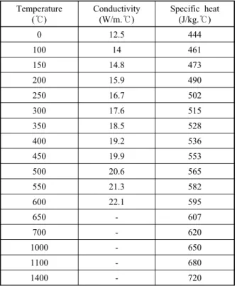
The thermo-physical material properties incorporated in the research are presented in Table 2.
3.3 Mechanical analysis of ebw process
For mechanical analysis, the same finite element mod- el presented in the thermal analysis is applied, and as discussed before, the thermal history obtained in the thermal analysis is applied as the load, and solution of the fundamental equations of elasticity and thermo-elas- ticity along with incorporation of the mechanical prop- erties attributed to the material (Table 3) lead to the de- sired results, i.e. residual stresses.
4. Results and discussion
In this section, the results associated with finite ele- ment modeling of EBW process are provided. First, the finite element code is validated through comparison with the results provided in
4). After enough confidence is reached about validity of the model, further pre-
Heat source Spherical Conical
q0(W/mm2) 215 -
R1(mm) 0.9 -
R2(mm) 1.3 -
Ri(mm) - 0.47
Re(mm) - 0.49
Zi(mm) - 2.7
Ze(mm) - 8.8
Table 1 Simulation parameters
Electron beam
20 50
55
Fig. 2 Geometry and dimensions of the simulated plates
Fig. 3 The finite element model applied
dictions and investigations about the effect of plate thickness on the residual stresses are made.
4.1 Validation of the model
Fig. 4 displays the stress contours during electron beam welding of the plates.
Figs. 5 and 6 compare the transverse and longitudinal stresses obtained through the present study and those of
4)
. As observed, good agreement exists between the re- sults, which reveals the validity of the procedure.
4.2 pre-heat treatment
Inconel 706 is a wrought Ni-Fe base super alloy which is widely used in the gas turbine Industry. e.g. for disc applications, because of its balanced manufacturability and elevated temperature strength. Heat treatment is an indispensable step in the manufacture of Inconel alloy products. However, apart from the desired effects, the heat treatment process can be accompanied by unwanted effects such as component distortion, increased residual which can lead to fatigue failure. Therefore, success or failure of heat treatment not only affects manufacturing costs but also determines product quality and reliability.
Heat treatment must therefore be taken into account
Temperature (℃)
Conductivity (W/m.℃)
Specific heat (J/kg.℃)
0 12.5 444
100 14 461
150 14.8 473
200 15.9 490
250 16.7 502
300 17.6 515
350 18.5 528
400 19.2 536
450 19.9 553
500 20.6 565
550 21.3 582
600 22.1 595
650 - 607
700 - 620
1000 - 650
1100 - 680
1400 - 720
Table 3 Mechanical properties of Inconel 706
15)Temperature (℃)
Yield Stress (MPa)
Thermal Expansion Coefficient
(℃)
Young’s Modulus (GPa)
Poisson’s Ratio
0 383 1/30×10-5 204 0.382
100 369 1/41×10-5 193 0.389
200 352 1/45×10-5 187 0.392
300 339 1/50×10-5 181 0.403
400 336 1/54×10-5 176 0.404
600 316 1/60×10-5 165 0.395
700 272 1/64×10-5 155 0.415
1000 52 1/78×10-5 72 0.420
1100 45 1/90×10-5 30 0.432
1400 20 2×10⁻⁵ 25 0.440
Table 2 Thermo-physical properties of Inconel 706
15)Fig. 4 Stress contours during EBW process simulation
Residual stress(MPa)
Displacement from weld line(mm) 100
50
0
-50
-100
-150
0 5 10 15 20
Transverse stress
Refrence
Simulation
Fig. 5 Comparison of simulation results and those of
4)(transverse stresses)
500
400
300
200
100
0
-100
-200
0 5 10 15 20
Displacement from weld line(mm)
Refrence
Simulation Longitudinal stress
Residual stress(MPa)
Fig. 6 Comparison of simulation results and those of
4)(longitudinal stresses)
during development and design, and it has to be con- trolled in the manufacturing process and considered in welding processes.
Ultimate strength and 0.2% offset yield strength of Inconel 706 weldments at room temperature, 1200 F (649 C), and 1400 F (760 C) was above 90% that of base metal and in most cases exceeded the minimum level specified by AMS 5596 and MIL-Hdbk-5B for base metal
16).
4.3 Pre-heat treatment procedures]
Solution anneal at 1700 to 1850 F and air cool. Then there are 2 follow on heat treatments: For optimum creep/
rupture properties follow the solution anneal with 1550 F for 3 hours, air cool -- then 1325 F precipitation treat- ment for 8 hours followed by cooling rate of 100 F per hour down to 1150 F. Hold at 1150 F for 8 hours and air cool. For optimum tensile strength follow the solution anneal with 1350 F precipitation heat treatment for 8 hours, followed by cooling rate of 100 F per hour down to 1150 F. Hold at 1150 F for 8 hours and air cool. This treatment eliminates the 1550 F thermal treatment
17). 4.4 Effect of base metal heat treatment prior to
welding on residual stresses
After enough confidence is found, it is available to study the effect of heat treatment on the distribution and magnitude of the residual stresses. The results presented in Figs. 5 and 6 were obtained making use of heat treat- ed material properties, as used in
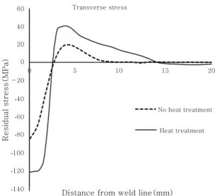
4). An important ques- tion to be answered is how heat treatment of initial ma- terials affects the final residual stresses. In other words, does heat treatment which allows for much higher strength for the material include any drawbacks? Heat treatment imposes dramatic changes in the plastic properties of the material. In this regard, the mechanical properties of non-heat treated Inconel 706 were incorporated and the residual stresses were calculated and compared to the initial results. The results are presented in Figs. 7 and 8 for longitudinal and transverse stresses, respectively.
As presented, heat treatment of the material imposes vast changes in the residual stresses, which needs to be taken into consideration. This occurs as a consequence of the fact that the maximum residual stress tends to equal the yield strength. Therefore, the increase in re- sidual stresses as a result of heat treatment leads to a dramatic increase in the residual stresses which imposes practical limitations.
4.5 Effect of plate thickness on residual stresses After studying the effect of heat treatment, plate thick-
ness effect is another parameter studied in this work. In this regard, thicknesses of 10 mm and 2.5 mm were considered and compared to the original thickness of 5 mm (twice and half the original thickness). Figs. 9 and 10 illustrate this comparison.
Reflection on the presented results reveals that in- crease in the thickness of the plates leads to rise in the maximum residual stresses, which can be justified through consideration of the stricter internal constraints within the material that occurs with increase in the material thickness. This is a significant result as EBW is espe- cially applied on plates with high thickness, and this fact must be considered.
5. Conclusions
In this study, finite element simulation of electron beam welding was studied in order to investigate the ef- fect of heat treatment (on base metal before welding) and plate thickness on the distribution and magnitude of welding residual stresses. The results obtained in
4)were
400 350 300 250 200 150 100 50 0 -50 -100 -150 -200
Residual stress(MPa)
Longitudinal stress
Displacement from weld line(mm)
No heat treatment
Heat treatment
0 5 10 15 20
Fig. 7 Effect of heat treatment on longitudinal stresses
Residual stress(MPa)
Transverse stress
Distance from weld line(mm)
60
40
20
0
-20
-40
-60
-80
-100
-120
-140
0 5 10 15 20
No heat treatment
Heat treatment