Nonlinear Observer Design for Dynamic Positioning Control of a Surface Vessel
선박운동제어를 위한 비선형 관측기 설계
Y. B. Kim* and J. S. Jang**†
김영복*․장지성**†
(received 17 August 2012, revised 26 September 2012, accepted 27 September 2012)
Key Words:DPS(Dynamic Positioning System), 비선형관측기(Nonlinear Observer), 슬라이딩모드제어(Sliding Mode Control), 트랙추종(Trajectory Tracking)
Abstract:본 논문에서는 항내에서 저속으로 운동(항해)하는 선박의 운동제어문제에 대해 고려하고 있다. 항 내에서는 특히 그 운동속도가 느리므로 일반 항해에서와는 달이 저주파대역에서의 운동특성이 중요하다. 대 부분의 중대형선박이 항내에서 터그보트에 의해 접안시설로 이동하게 된다. 이러한 사실을 고려하여 대상선 박이 4기의 터그보트에 의해 제어되는 선박의 제어계 설계문제에 대해 고찰하고 있다. 주요 연구내용은 크 게 두가지로 구분된다. 첫째 비선형특성이 강하게 포함되어있는 선박운동특성을 고려하여 비선형관측기를 설계한다. 이것은 특히 저주파수 대역에서 선박의 위치와 속도 등 제어신호를 계산하는데 필요한 정보를 추 정하는데 유효한 방법으로 잘 알려져 있다. 이를 기반으로 외란 등에 강인한 슬라이딩모드 제어기를 설계한 다. 결과적으로 비선형관측기를 포함한 슬라이딩모드제어기의 유용성을 시뮬레이션을 통해 검증하였으며 이 결과는 실험을 위한 유용한 기초자료로 활용될 것이다.
**†장지성(교신저자) : 부경대학교 기계시스템공학과 E-mail : [email protected], Tel : 051-629-6196
*김영복 : 부경대학교 기계시스템공학과
**†J. S. Jang(corresponding author) : Department of Mechanical System Engineering, PuKyong National University.
E-mail : [email protected], Tel : 051-629-6196
*Y. B. Kim : Department of Mechanical System Engineering, PuKyong National University.
1. Introduction
Dynamic positioning system(DPS) has been applied on vessel since the 1960s, and today DPS is equipped on many new vessels which are freight transport and offshore exploration etc.
The trend on DPS was discussed on a survey paper by Sorensen1). The main objective of the DPS is to make sure that the ship maintains the fixed position and heading or follows a predetermined track in the horizontal plane by using propulsion system. In this paper, maneuvering problem of vessel in harbor area is considered with DPS system. As well known, ship berthing operation requires high accuracy
for tracking mission to avoid collision between ship and the other moving vessel in this area and between ship and jetty. Unfortunately, in harbor area, DPS performance cannot guarantee the safety for ship berthing. The reason is that controllability of propulsion system considerably reduces at slow or dead speed. So the propulsion system of heavy vessel is provisionally not used in berthing operation and slow motion control of ship. Therefore berthing job is usually done by assistance of tugboats. To overcome this drawback and try to build up an automatic system for ship berthing, we propose an approach by using autonomous tugboats as shown in Fig. 1. In this approach, the tugboats
are attached to the mother ship at fixed direction.
Then the mother ship motion control will be done by the combination of only pushing forces from the tugboats. To design the controller for ship berthing, the motion of ship in the presence of environmental disturbances is considered.
Environmental disturbances affecting the ship motion are separated into two parts: slow frequency components and wave frequency components. However, only the slow frequency disturbances due to wind, wave and current should be processed by propulsion system. The high frequency disturbances are out of the bandwidth of actuator response and should be eliminated in the feedback loop of controller. This is done by using a nonlinear passive observer proposed by Fossen2). The advantages of the nonlinear observer are that it includes the wave filter, bias state estimation for the slow frequency disturbances. Additionally, it can estimate the low frequency position and velocity of the ship from noisy position data measured by DPS system and gyro compass. Notice that the velocity measurement of ship is almost not available on vessel system. With uncertainty and complexity of ship dynamics and environmental disturbances, the authors propose a robust controller by using sliding mode control(SMC) technique. The SMC technique has been applied for path following control of ship in restricted water3) and trajectory tracking of underwater
Fig. 1 Controlled system by using tugboats
vehicle4) etc. The SMC presented in this paper guarantees robust performance and remarkable stability with nonlinear observer to cope with disturbances, based on our previous results5,6).
2. System and Disturbance Model
The dynamic positioning of a surface ship can be described by the following model7)
(1)
where ∈ represents inertial position (x, y) and heading angle in the earth fixed coordinate frame and, ∈ describes surge, sway and yaw rate of ship motion in the same frame. The rotation matrix in yaw describes the kinematic equation of motion, that is
cos sin sin cos
. (2)
The inertia matrix including added mass
∈ × is written as
, (3)
where m is the vessel mass and is the moment of inertia about the vessel fixed z-axis.
For control application, we can assume that
.
For a stable ship following a straight line, R3x3
∈
D is considered as positive damping matrix. The linear damping matrix is defined as
, (4)
where ∈ is the control input composed of forces and moments provided by the propulsion system. It may include the main propellers of the ship, bow and stern thrusters. In this paper,
it is considered that the propulsion system is replaced by the tug boats. The vector is the result of combined efforts of four tugboats. This vector is defined as follows:
(5) where the vector ∈
represents the thrusts produced by several tugboats.
Furthermore, m ax, ∀ ∈ .
The geometric configuration matrix
∈ × captures the relationship between all four tugboats and the mother ship. The i-th column of matrix is defined as
cos sin
cos sin
, (6)
where the angle defines the force direction of the i-th tugboat. Measuring it clockwise, it is relative to the x-axis of the body fixed coordinate frame. The location of the i-th contact point in the body fixed coordinate system is at
. Thus the control input vector can be expressed by the form of the geometric configuration matrix and thrust vector as
(7)
where sin , cos. In this paper, the contact positions between the ship and the tugboats as well as tugboat directions are assumed to be fixed. The adequate set is solved by using the control allocation approach8-10).
2.2 Low frequency environmental disturbance The low frequency environmental disturbances applied for marine control application can be modelled as a first order Markov model as following:
, (8) where ∈ is the vector of bias forces and moment, ∈ is the vector of zero-mean Gaussian white noise. ∈ is the diagonal positive bias time constants matrix and ∈ × is the diagonal matrix scaling the amplitude of white noise disturbances . This model can be used to describe slow varying environmental forces and moment due to second order wave drift, ocean current, wind and unmodelled dynamics etc.
2.3 Wave induced motion
The ship motions comprise two components.
They are the low frequency motion and the wave induced motion . The second component induces the oscillation on motion and should be eliminated from the feedback loop of controller. To filter out wave frequency components, a wave induced motion is proposed as following7):
I
, I
(9) with
∈,
diag
diag diag ,
where ∼ is the relative damping ratio,
∼ is the dominating wave frequency and ∼ is the parameter related to wave intensity. In equation (9), is assumed to be a vector of zero mean Gaussian white noise.
3. Nonlinear Observer and SMC Controller Design
3.1 Nonlinear observer design
As mentioned before, to filter out the wave frequency component and estimate the bias term of low frequency as well as velocity of ship from
noisy position measurements, the passive nonlinear observer is introduced in this paper.
The observer structure can be modified as follows2):
y
yv y
b b
y
v v yb
yy
y
(10)
where y y y is the error between the measured and estimated position and heading.
∈ × ∈ × ∈ × ∈ × are observer gain matrices. Where the observer gain is the function of dominating wave frequency component , whereas the gain matrices are independent on
. In practice, is a positive value and observer gain matrices can be chosen as following structure.
, (11)
. (12)
Notice that all element of observer gain matrix must be positive to satisfy the globally exponentially stable property of proposed observer.
3.2 Sliding mode controller(SMC) design
With insensitivity to dynamic variation and robustness to environmental disturbances, SMC is introduced in this study.
Definition 1: The measure of tracking is defined as
, (13)
where ∈ × is diagonal positive design matrix, is the Earth-fixed tracking error. The desired trajectory in the Earth fixed coordinated frame is denoted by vector
. Notice that the convergence of
to zero implies that the tracking error approaches to zero.
Definition 2: The virtual reference trajectory is defined as
(14) To simplify the development of controller design, the system model represented in equation (1) is rewritten as follows:
(15) Where the transformed system matrices
∈ × , ∈ × and ∈ are calculated as follows:
(16)
And, the skew symmetric matrix ∈ × in equation (16) is defined as follows:
. (17)
The differential equation of the sliding mode is derived by
. (18) Letting , then the equivalent control can be obtained by
. (19) And the control input of SMC is defined as
*= eq+ sw,
τ τ τ (20)
where is switching control part. To guarantee that the sliding mode tends to zero in infinite time. The dynamics of sliding mode is
chosen to have the following form
sgn, (21) where ∈ × and ∈ × are the designed diagonal positive matrices.
Based on equation (21), the can be chosen as
sgn . (22) Totally, the control input is designed as
sgn (23) A non-negative Lyapunov function is chosen to analyze the stability of system. It is given by in general form
. (24)
Then the derivative of V along the trajectory of system is
(25)
Substituting the control input in equation (23), then we have
sgn ≤ (26) It means that equation (26) gives the non-positive time derivative of the Lyapunov function candidate. Based on the Lyapunov stability, it is possible to conclude that the control system is asymptotically stable. To reduce the chattering in SMC controller, the discontinuous signum function in equation (23) is replaced by the saturation function as following:
sat i f
sat sgn otherwise (27) where is a boundary layer thickness.
At last and totally, the control input will be calculated as
sat
(28)
4. Simulation Results
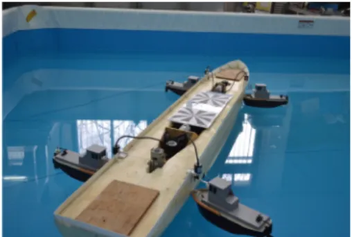
To evaluate performance and robustness of proposed method, a computer simulation has been done. The case study is based on the model ship which was made by ourself and shown in Fig. 2.
The ship length is 2.05[m], and the mass is 24.5[kg]. The origin of the body fixed coordinate frame coincides with the center of gravity.
Fig. 2 A model ship used for simulation
The inertia and damping matrices are evaluated as following:
(28)
As a berthing simulation, the ship is maneuvered from point A(0, 0) with heading angle to point B(10, 10) with final heading angle. Where the reference route and velocity are generated from a second order reference model given by
(29)
with
. And the slow varying bias term in equation (8) and SMC parameter are chosen as following:
diag
diag
×
(30)
In the result, the ship motion is shown in Fig.
3. From this figure, it is clear that good tracking performance can be achieved in the presence of disturbances. Notice that the thrust produced from tugboat is activated with only pushing
Fig. 3 Ship motion by using nonlinear passive observer with SMC control
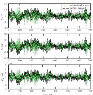
Fig. 4 Wave disturbances estimation results
Fig. 5 The thrust forces produced from each tugboat
direction. Fig. 4 shows parameter estimation performance of designed nonlinear observer. As shown in this figure, it is clear that the wave disturbances can be estimated from the noisy position measurement data with high accuracy.
From the control input, the force which is supplied from each tugboat is solved by using control allocation technique given in the previous results.8-10) It satisfies the pushing force constraint(0.5[N]) of the tugboat also, as shown in Fig. 5.
5. Concluding Remarks
In this paper, the authors proposed a new approach for dynamic positioning problem in the harbor area by using nonlinear observer and sliding mode controller. The nonlinear observer has shown that the wave frequency disturbances can be accurately estimated. And the low frequency motion of ship can be reconstructed from measured position data with noise. The designed controller shows good performance and robustness to environmental disturbances. This result guarantees that we can achieve good control performance in the experiment study.
Acknowledgement
This work was supported by the Pukyong National University Research Fund in 2011(PK-2011-61)
References
1. A. J. Sorensen, 2011, “A Survey of Dynamic Positioning Control Systems”, Annual Review in Control, Vol. 35, pp. 123-136.
2. T. I. Fossen and J. P. Strand, 1999, “Passive Nonlinear Observer Design for Ships Using Lyapunov Methods: Full-Scale Experiments with a Supply Vessel”, Automatica, Vol. 35, pp. 3-16.
3. R. Zhang, Y. Chen, Z. Sun, F. Sun and H.
Xu, 2000, “Path Control of a Surface Ship in Restricted Waters Using Sliding Mode”, Transactions on Control System Technology, Vol. 8, pp. 722-732.
4. A. J. Healey and D. Lienard, 1993,
“Multivariable Sliding Mode Control for Autonomous Diving and Steering of Unmanned Under Water Vehicles”, Journal of Ocean Engineering, Vol. 18, pp. 327-339.
5. H. M. Bae, V. P. Bui, D. S. Lee and Y. B.
Kim, 2010, “A Development of Constrained Control Allocation for ship Berthing by Using Autonomous Tugboats”, Journal of the Korean Society for Power System Engineering, Vol. 14, No. 6, pp. 96-101.
6. V. B. Bui and Y. B. Kim, 2012, “A Study on the Development of Dynamic Positioning system for Barge Type Surface Vessels”, Journal of the Korean Society for Power System Engineering, Vol. 16, No. 2, pp.
66-74.
7. Thor. I. Fossen, 2002, “Marine Control System-Guidance and Navigation, Rigs and Underwater Vehicle”, Trondheim, Norway, Norwegian University of Science and Technology.
8. V. P. Bui, H. Kawai, Y. B. Kim and K. S.
Lee, 2011, “A Ship Berthing System Design with Four Tugboats”, Journal of Mechanical Science and Technology, Vol. 25, pp.
1257-1264.
9. B. V. Phuoc and Y. Kim, 2011, “Design of Sliding Mode Controller for Ship Positioning Control”, Journal of Institute of Control, Robotics and Systems, Vol. 17, No. 9, pp.
869-874.
10. B. V. Phuoc and Y. Kim, 2011, “A Study on the Development of Dynamic Positioning System for Barge Type Surface Vessels”, Journal of the Korean Society for Power System Engineering, Vol. 16, No. 2, pp.
66-74.