스마트 반강접 (PR) 콘크리트 충전 강재 합성 (CFT) 접합 구조물에 대한 해석모델의 개발
Development of A Component and Advanced Model for The Smart PR-CFT Connection Structure
선우현 Seon, Woo-Hyun
* ‧
허종완 Hu, Jong-Wan**†(Received August 30, 2011 ; Revised December 1, 2011 ; Accepted December 15, 2011)
ABSTRACT
This study investigates the performance of composite (steel-concrete) frame structures through numerical experiments on individual connections. The innovative aspects of this research are in the use of connections between steel beams and concrete-filled tube (CFT)columns that utilize a combination of low-carbon steel and shape memory alloy (SMA) components. In these new connections, the intent is to utilize the recentering provided by super-elastic shape memory alloy tension bars to reduce building damage and residual drift after a major earthquake. The low-carbon steel components provide excellent energy dissipation. The analysis and design of these structures is complicated because the connections cannot be modeled as being simply pins or full fixity ones they are partial restraint (PR). A refined finite element (FE) model with sophisticated three dimensional (3D) solid elements was developed to conduct numerical experiments on PR-CFT joints to obtain the global behavior of the connection. Based on behavioral information obtained from these FE tests, simplified connection models were formulated by using joint elements with spring components. The behavior of entire frames under cyclic loads was conducted and compared with the monotonic behavior obtained from the 3D FE simulations. Good agreement was found between the simple and sophisticated models, verifying the robustness of the approach.
요 지
본 연구는 각 연결부에 대한 수치 해석을 통하여 강재-콘크리트 합성 프레임 구조물의 성능을 조사하였다. 본 연구 의 혁신적인 측면은 강재 보와 CFT 기둥의 연결부 사용과 저탄소강과 형상 기억 합금 구성요소의 조합을 활용하 는데 있다. 이러한 새로운 연결부의 목적은 지진 후 건물의 손상과 잔류 흐름을 줄이기 위해 고탄성 형상기억합금 인장부에서 발생하는 교정 작용과 저탄소강의 우수한 에너지 분산 능력을 활용하는 것이다. 연결부의 핀, 전체적인 고정 또는 부분 구속으로 모델링을 할 수 없기 때문에 이러한 구조물들의 해석과 설계는 복잡하여 PR-CFT 연결부 의 전체적인 거동을 알기 위한 수치해석을 위해 정교한 3차원 솔리드 요소로 구성된 유한해석 모델을 개발하였다.
이러한 유한요소 해석으로 얻은 결과를 바탕으로 스프링 요소를 이용하여 간단한 연결부 모델링을 공식화 시켰다.
반복 하중을 가하여 전체 프레임 구조물의 거동을 확인하였고 3D 유한요소 해석을 통하여 단순 거동을 비교하였 다.
Key Words: Shape Memory Alloy(SMA); Partially-restraint (PR); Concrete filled tube (CFT); Finite element (FE);
Connections
* 정회원‧동명기술공단 건축사사무소 철도부 사원
**†
정회원
‧
한국과학기술기획평가원 부연구위원, 교신저자([email protected])1. Introduction
In recent years, concrete filled steel tube (CFT) columns have become widely accepted and used in multistory buildings as well as bridges. These elements provide the synergetic advantages of ductility and toughness associated with steel structures and high compressive strength associated with confined concrete components. The advantages of CFT columns over other so-called mixed or
hybrid systems (fully encased or partially encased
systems) include the fact that the concrete prevents local
buckling of the steel tube wall and the confinement
action of the steel tube extends the usable strain of the
concrete. In addition, CFT columns have improved fire
resistance and significant cost reductions in comparison
with traditional steel construction. Composite CFT
columns are especially efficient as the vertical elements in
moment resisting frames in high seismic areas because
they have a high strength to weight ratio, provide excellent monotonic and dynamic resistance under biaxial bending plus axial force, and improve damping behavior (Tsai et al. 2004).
To evaluate the performance of a moment frame structures subjected to lateral-loads, the flexural and shear effects on the deformation on the framing members and connections are the critical issue. In this study, the shear deformations are ignored because the concrete inside the tubular columns considerable reduces the contribution of shear deformations to the overall joint displacements. In addition, because the behavior of both beams and columns as isolated members is well-understood, this study focuses on connection behavior only. For stiffness, connections are classified as fully restrained (FR), partially restrained (PR) or simple pinned connections. An ideal pinned connection only transmits shear from the beam to columns and is considered as a simple connection. At the other extreme, connections where no change in angle occurs between the beam and column are classified as FR. Most real connections in steel buildings fall somewhere between these two extremes and are PR ones. For strength, connections are classified as either full strength (FS) or partial strength (PS) depending on whether they can transmit the full plastic moment (M
p) ofthe beam. Finally, connections are classified as brittle or ductile connections based on their ability to achieve a certain plastic rotational demand. For example, in the aftermath of Northridge earthquake, an elastic rotation of 0.01 radians and a plastic rotation of 0.03 radians under cyclic loading have been accepted as the rotational limit to distinguish between ductile and brittle connections in special moment resisting frames. The major failures of fully welded moment connections during the 1994 Northridge and 1995 Kobe earthquakes have led to the conclusion that the traditional fully welded moment connections (FR/FS) have several structural disadvantages and that bolted connections or combinations of field bolted-shop welded connections pose an attractive solution to this brittle failure dilemma (Swanson and Leon 2000).
It also has been demonstrated that well-detailed PR structures can provide similar or superior seismic behavior to their FR counterparts (Rassati et al. 2004).
More recently, work at Georgia Tech on shape memory alloys (SMA) has explored the applications of
this material to the design of connections in steel structures subjected to large cyclic loads. SMA materials can undergo large deformations with little permanent residual strain through either the shape memory effect or the super-elastic effect. The deformations can be recovered with changes in either temperature or stress as shown in Figure 2. This type of connection (See Figure 3) not only contains all of merits of bolted PR connections mentioned above, but also contains a recentering capacity because of the lack of permanent residual deformation in the tendons due to the SMA material characteristics (Penar 2005).
Fig. 1 The 3 story by 3 bay CFT composite frame with buckling restrained brace (Tasi, K.C et al., 2004)
This research intends to explore a mixture of steel bars and super-elastic Nitinol bars as connecting elements to CFT columns. It is hypothesized that such combinations of CFT columns and SMA connections will achieve excellent ductility, high strength, and recentering capability. The structural combinations and advantages for this "smart PR-CFT" connection, as well as the whole approach for this research, are summarized schematically in Figure 3.
Fig. 2 The stress and strain behavior and connection application for super-elastic (SE) SMA materials
(Penar, 2005)
Based on these premises, numbers of original connetion
models were developed to investigate the optimal
distribution of steel and SMA components. Because of
space limitations, this paper deals with only one of those designs (i.e., end plate connections). The paper is divided into four parts. Section 2 describes the new connection design and the materials used. Section 3 discusses the initial detailed finite element analyses used to develop an understanding of the monotonic moment-rotation behavior of the connections as well as the contribution and influence of different deformation mechanisms. Section 4 describes the use of the detailed results from Section 3 on the development of a simpler model for use with cyclic loads. Section 5 provides the conclusions.
Fig. 3 Structural advantages for the new composite connection model
2. New Connection Designs
All connections in this study were designed as full strength (FS), meaning that they can transfer the full plastic beam moment (M
p) calculated according to the LRFD Standard (AISC 2001).The connection design, however, did not aim to achieve full restraint (FR or full end rigidity); it intended to utilize PR behavior to obtain ductile connection behavior. The connection selected for discussion in this paper is an end plate one (Figure 5).
Since some shear yielding and local buckling have been observed in the panel zone of I-shape steel columns before reaching the full moment capacity of the connected beams, it was decided that the panel zone capacity should be upgraded by using a concrete-filled tube section to minimize these effects. Component members such as shear/web bolts, shear tab plates and clip angle or T-stubs
were designed with the intent of preventing or reducing loss of stiffness and strength due to brittle failure modes.
Therefore, the dominant failure modes of the steel or composite components should be ductile "yield" modes such as slip, yielding of steel, and minor local bucking.
This will avoid the potential for entire system collapse and improve the probability of survival (Astaneh-Asl 1995). All designs were carried out based on demand capacity principles, evaluated using the typical assumptions of weak beam and strong column conditions.
The connections were fabricated with an assembly of various steel members cut from standard shapes available in the current design specification (AISC 2001). A572 Grade 50 steel was used for all members and joint components. A490 high strength bolt material was used for steel bars, washers, and nuts. Super-elastic (SE) Nitinol bars, with the characteristics shown in Figure 2, were located where the largest deformations were likely to occur. Extended stiffener plates welded between the connected beam flange and the end-plate were required to maintain stiffness (Figure 4). The plate stiffeners had the same material strengths (A572-Gr. 50 Steel) as the beam and their thickness was equal to the beam web thickness.
(a) beam and column detail (b) connection details
Fig. 4 (a) Exterior and (b) interior connection
details
3. Three-Dimensional Finite Elements Analyses
3.1 Modeling Procedures
The ABAQUS (ABAQUS v.6.6-1, 2006) finite element
code was used to analyze these PR-CFT connection
subassemblies. The numerical models consisted of refined
3D solid elements (8 node brick element, C3D8)
incorporating the full nonlinear material/ geometric
properties, contact elements, surface interaction with friction, constraint conditions using equation points, concrete crack conditions, and elastic foundation modeling.
These modeling methods were useful to provide detailed and accurate understanding of the overall behavior of the connection, including the stress distributions on the contact surfaces. Of course, these advantages come both at a high computational cost during the runs and substantial time needed to overcome numerical instabilities in the solution algorithms.
In this research, most of FE work, including the generation of parametric geometries and meshes, was done by using ABAQUS/CAE with an input file-based edition to add more modeling flexibility. The FE models (i.e. end-plate connections plus beam and column stubs, Fig. 5(a))were subdivided into several independent bodies:
8 tension bars, welded end-plate component, structural beam, outside hollow steel column, and inside concrete material (Figure 5(b)). Each of these has its own material properties and interacts with each other via contact definitions. They were modeled as half symmetric models to save computation time. The assembled connection and component members are shown in Figure 5 (a).
Fig. 5 (a) Assembled connection and (b) 3D solid elements components (concrete, steel shell, end
plate and beam, and bolts)
Surface interactions with friction coefficients were defined for all component interfaces (Figure 6(a)). In addition, gap elements were used to generate the contact behavior along the normal direction to the surface between the steel column surface and inside concrete core as shown in Figure 6(b). The 3D solid elements incorporated nonlinear material properties as shown in Figure 7. The cyclic material behavior of SMA materials
was generated by a user-defined code (Davide, 2003) in OPENSEES because ABAQUS lacks such model.
Fig. 6 Advanced modeling for the contact between
steel and inside concrete
Fig. 7 Material properties for the analyses
The models were loaded in two steps. The first step was used to pretension the bolts while the second step was used to apply the main load. The bolts were pre-tensioned by applying an adjustment length / displacement to the surface of the bolt shank.
3.2 FE Analysis Results and Observations
The static monotonic loads were generated by imposing a support displacement to the tip of the beam. The force-displacement response of the connections ( ∆ ) was changed into a moment-rotation response using simple relationships ( , ∆ ).
For the end-plate connection, the stress distributions at the ultimate state are shown in Figure 8. Due to the contact interaction definition, bearing forces acting on the steel tube could be transferred into the concrete core.
High bearing pressures and crushing could be observed on the concrete underneath the bar heads.
The nonlinear moment-rotation behavior curve is shown in Figure 9. These connections exceeded both the full plastic strength of the beam (M
p) and the required rotational limit for ductility. This implies that this type of the connection can satisfy current design criteria with respect to strength, stiffness, and deformation capacity.
Structural failure modes for these connections can be determined from the distribution of stresses at ultimate for the different components. The Von-Mises stress at the column surface, the middle of the steel tension and SMA bars, and the beam were monitored as the applied static moment increased, are shown in Figure 10. Based on the classification of limit states, safe and unsafe behavior zones can be established (Fig. 10) and the performance of
the individual components checked. The connections behaved in a ductile manner and exceeded the full plastic strength of the beam (M
p).
Fig. 8 Stress distribution in the connection (left) and inside concrete (right)
Fig. 9 Plastic moment and rotation curves for
connection models
Fig. 10 Structural failure types based on the stress measurement
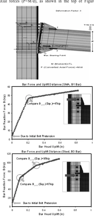
The results shown above, which constitute a fraction of those studied, provided detailed insight into the monotonic behavior of these PR steel-SMA connections. They also provided the foundation for the development of simpler models, as the 3D FE connection models shown above are unsuitable to the analysis of entire buildings. The later models will be based on the global behavior or moment-rotation curve for the entire connection. The conversion from these detailed results to a global model is carried out in a straightforward fashion. The total applied force (T) at the tip of beam is first converted
into a bending moment (M = TL). This bending moment is transmitted to the connection as a set of concentrated axial forces (P=M/d), as shown in the top of Figure 11.
Fig. 11 Reaction forces and deformations under the total applied force (T)
The graph of Fig. 11 shows the key points for the behavior of both the steel and SMA bars as the monotonic load increases. In order to fulfill equilibrium constraints, the summation of bar reaction forces (ΣB
i) must equal to the summation of the converted axial force and prying force (ΣB
i= P+Q).
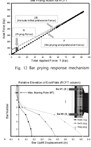
The prying response of the end-plate connections is
given in Figure 12. At the beginning of the loading
history, the prying force (Q) corresponds to the
summation of the bolt reaction forces due to the initial pretensions. However, the effect of prying force becomes negligible after the considerable axial force (P) is applied to tension bars. Thus the difference between P (total force) and ΣB
i(total force including prying) decreases as the load increases and vanishes at the ultimate deformation.
This bar prying response has an influence on both the external moment (M=TL) and the internal moment (M = ΣB
ih
i). Comparisons between the external moment and the internal reaction moment are given in Table 1. The external moments show good agreement with the internal moments, indicating that the simplifications made do not affect the prediction of response appreciably.
Table 1. Comparisons between external moment and internal moment
The uplift of the end-plate, depicted in Figure 13, shows the deformations at the bar locations. These results indicate that the FE models can capture the local behavior well. The components subjected to tension force show a different behavior from those subjected to compression force. SMA and steel bars subjected to tension follow their material property paths in terms of the relative deformation and the reaction force. Those subjected to the compression, however, were affected by the bearing because of their penetration into the surface of the CFT columns.
4. Connection Models under Cyclic Loads
Simple beam-to-column joint models for the PR-CFT connections were constructed using the nonlinear finite
Fig. 12 Bar prying response mechanism
Fig. 13 End-plate elevation at the bar head
element (FE) program OpenSEES (OpenSEES v. 1.7.3, 2006). A 2D joint model is appropriate for use in frame analyses to estimate the inelastic response of moment frames under cyclic loading such as that imposed by large earthquakes. The primary objective of this study is the development and implementation in simplified joint models reflecting the real connection behavior.
4.1 Simplified 2D Joint Model
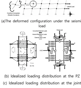
The idealization of the moment distribution at the
perimeter of a typical panel zone under cyclic loads is
shown in Figure 14(a). Figures 14(b) and (c) show the
idealization of the force distribution at the perimeter of
the joint model for the end-plate connection. As shown in
these figures, the connection components, such as the
tension bars, are converted into equivalent spring
elements. In addition, the end-plate is modeled as a rigid
plate, as the end plate contributes little to the deformation
of the overall connection. This joint model includes
spring elements for the CFT column and panel zone as
well as those for the connection bars. The external moments acting on the beams and columns are assumed to transfer into the equivalent concentrated force resultants (P forces in Figure 14(b)). The internal resistant loads of connection components act against these converted external forces as shown in Figure 14 (c) in order to satisfy the equilibrium.
Cruciform Connection (Double Curvature)
M M
An idealization of the moment distribution
Lateral Load
(a)The deformed configuration under the seismic load
Converted External Loads Internal Resistance Loads
T M
P
P V B1 A1
B2 B3 B4
B5 B6 B7 B8 A2
A3
B9
T = V M = Pd
P V P Dead Load
External (EQ) Loads
P
P d
(b) ldealized loading distribution at the PZ (c) ldealized loading distribution at the joint
model
Fig. 14 (a), (b), and (c). External and internal forces at the joint model (End-plate connection)
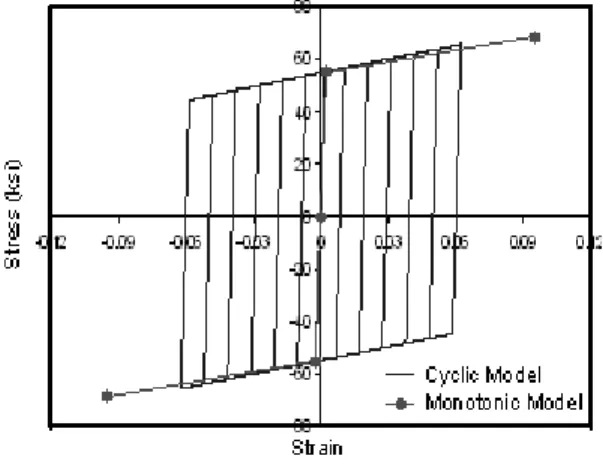
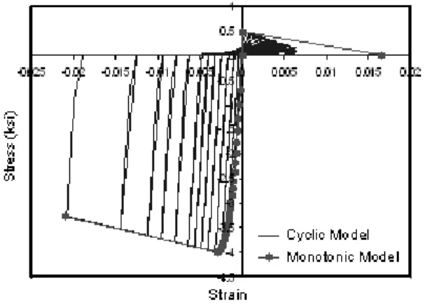
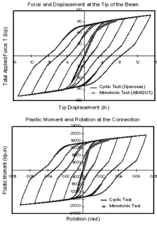
The response mechanism of the joint element under bending deformation is shown in Figure 15. The joint model under seismic loading is deformed in shear (scissors) mode. The external axial forces are transferred into the connection components modeled as spring elements in the program. The internal tension loads corresponding to the external force are directly carried by tension bars as shown in Figure 15 (a). The behavior under compression / bearing was determined by observations from the 3D FE models. The equivalent element shown in Figure 15(b) reduces the number of variables during the analysis, both saving running time and avoiding numerical convergence problems. The cyclic behavior of the equivalent spring elements is compared with the converted axial force vs. corresponding deformation obtained from static 3D FE test in Figure 16.
During the loading path, the test results from the 3D FE
models show good agreement with that of the equivalent spring element.
Fig. 15 (a) and (b). The response mechanism of the joint element under bending
The solution for the case of cyclic loads algorithm was based on incremental displacement control. Comparisons between results of the algorithm and those of 3D FE model test are given in Table 2. Both the displacements and forces results show very good agreement.
Fig. 16 Test methods and comparisons of results
between two analytical tests
Table 2. Comparisons of the bar responses at two analytical tests
The joint models presented above were modeled as 2D joint elements in the OpenSEES program, which allows the development of user-defined elements such as the one described here (Figure 17.) This element includes four equivalent spring elements (S1) to reproduce the behavior of the component model, four internal spring elements (S2) reproduce the axial deformation of the CFT column, four internal shear springs (S3) to reproduce the shear deformation of the CFT column and the beam, and one shear panel element (C) which is intended to reproduce the failure of the panel zone under severe loading. The joint model includes one element of the beam and column. In OpenSEES, the beam and CFT column are modeled as a nonlinear beam-column element with 2D fiber sections.
Fig. 17 (a) and (b). The typical joint element for a joint model
4.2. Test Results