Objective: To evaluate the factors that affect torque control during anterior retraction when utilizing the C-retractor with a palatal miniplate as an exclusive source of anchorage without posterior appliances
12
0
0
전체 글
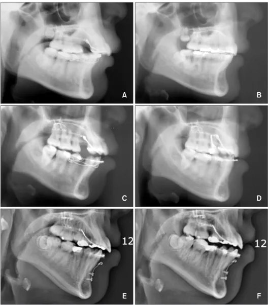
(2) Mo et al • Torque control in lingual orthodontics. INTRODUCTION Lingual orthodontics, a more esthetic orthodontic technique than labial orthodontics, has developed rapidly in recent years.1-3 Many case reports and papers have documented the treatment effects, and a variety of bracket designs have been produced.4,5 The disadvantages of lingual orthodontics include the excessive chair time, complicated biomechanics, patient discomfort, expensive lab procedures, and high material prices.6,7 However, several innovations have improved the use of lingual orthodontics, such as customized lingual brackets and 2-dimensional lingual brackets that can be bonded directly.8,9 Nonetheless, the efficient control of anterior torque and intrusion during retraction continues to be a limiting challenge. Mini-screws and mini-implants (the osseointegrating type) have been successfully applied to lingual orthodontics.9,10 Mini-implants placed on each side of the palate have been used to avoid uncontrolled tipping and the deepening of the anterior bite during en masse retraction. Typically, the treatment protocol involves the soldering of a lever arm to the main lingual archwire.10,11 The lever arm moves the force vector apically and closer to the center of resistance, thereby allowing better control of torque during retraction. One disadvantage of this mechanics is that play within the slot allows some of the torque to be lost during retraction. In addition, if bilateral mini-implants are not in the same horizontal. plane, which is sometimes required by the anatomy of the maxilla, the clinician may see unwanted canting of the occlusal plane due to different force vectors generated during retraction. Moreover, the sliding mechanics in a full-arch appliance using mini-implant-assisted anterior retraction may be adversely affected by friction within bracket slots and tubes, causing unwanted distalization of posterior teeth. Several recent reports12,13 have introduced “lingual biocreative therapy” into lingual orthodontics. This new treatment system allows en masse retraction of the anterior teeth independently of the posterior teeth by using a C-retractor and palatal miniplate (Figures 1 and 2). The C-retractor is constructed by soldering a 0.9-mm stainless steel wire onto mesh-bonding pads and is subsequently bonded to the lingual surfaces of the 6 or 8 anterior teeth.14 Unlike typical bracket/ archwire setups, slot play is not an issue in this type of setup. Furthermore, the C-retractor is adequately rigid to resist deformation under a normal retraction force. This particular feature facilitates control of the axes of the anterior teeth during retraction of the anterior segment. Also, selection of the appropriate vertical height of the lingual anterior retraction hooks (LARHs) allows the clinician to produce controlled tipping, bodily movement, and lingual root movement during retraction (Figure 3). Patient compliance is unnecessary, and patient comfort is improved when compared to lingual brackets.. Figure 1. A first premolar extraction case using the lingual biocreative therapy. A and D, Lingual en masse retraction forces are initiated. B and E, Seven months of en masse retraction. Triangular elastics were applied to the canine for vertical control. C and F, Post-treatment. The total treatment period was 13 months.. 4. http://dx.doi.org/10.4041/kjod.2013.43.1.3. www.e-kjo.org.
(3) Mo et al • Torque control in lingual orthodontics. Figure 2. A second premolar extraction case using the lingual biocreative therapy. A to C, Pre-treatment photos show dens evaginatus on #15 and a malformed #25. D to F, One month after en masse retraction force is initiated. G to I, Four months of en masse retraction. For cases in which the upper second premolars are affected by certain conditions (e.g. , dilacerated roots, short roots, compromised teeth, or dens invaginatus), extraction of the second premolars is usually indicated, even though the goal of lingual biocreative therapy is maximum anterior retraction. In a previously cited clinical study,12 miniplates in the palate (C-plates; Jin Biomed Co., Bucheon, Korea) were the only source of anchorage for the en masse retraction of the 6 or 8 maxillary anterior teeth. No appliances were placed in the upper and lower posterior dentitions. The C- plates were designed to have adjustable extension wings to allow the clinician to alter the force vectors. Further, the C-plate is fixed to the cortical bone of the maxillary palate, and a flap does not need to be laid. Hence, damage to the roots of adjacent teeth or anatomical structures is not a concern. Since the applied orthodontic forces during anterior retraction are against the C-plate and not against orthodontic appliances fixed to. www.e-kjo.org. http://dx.doi.org/10.4041/kjod.2013.43.1.3. the posterior teeth, no change in the posterior occlusion is expected during retraction.12,13,15 To date, however, no studies have analyzed the force systems involved in the control of anterior torque and intrusion by this technique, with the exception of studies in clinical literature and case reports. The aim of this study was to use finite element analysis (FEA) to evaluate the effectiveness of anterior segment retraction using the C-plate while varying the vertical height and location of the C-retractor hook.. MATERIALS AND METHODS Construction of the base finite element model We obtained tooth outlines by performing threedimensional (3D) laser scanning of a right maxillary tooth from a dental study model of the normal adult dentition (Nissin Dental Products Inc., Kyoto, Japan). We aligned and leveled the dental arches using a broad. 5.
(4) Mo et al • Torque control in lingual orthodontics. Figure 3. Pre- and post-lateral cephalograms. A and B, Low lingual anterior retraction hook (LARH) - the patient needed controlled lingual tipping; hence, a LARH vertical height of 4 mm was used. C and D, High LARH - the patient needed bodily tooth movement; thus, a LARH vertical height of 13 mm was used. E and F, Second premolars were extracted due to internal resorption, so the 8 anterior teeth were retracted using the lingual biocreative therapy. arch form (Ormco, Glendora, CA, USA) and referred to previous studies to assign inclination and angulation.16,17 Neither a curve of Spee nor a curve of Wilson was added (Figure 4). The thickness of the periodontal ligament was assumed to be uniform (0.25 mm).18 The alveolar bone crest was constructed to follow the cemento-enamel junction (CEJ) curvature 1 mm apical to the CEJ. The 3D-finite element model included 12 teeth, an open space to correspond to the missing first premolars or second premolars, periodontal space and alveolar bone. The model was also bilaterally symmetrical. In the finite element model, the teeth, alveolar bone, and periodontal spaces were constructed with fine tetrahedron solid elements, and node-to-node contact elements were installed between adjacent teeth to represent tooth. 6. Figure 4. Three-dimensional finite element mesh with teeth, periodontal ligament, alveolar bone of the maxillary dentition, and C-retractor with the low lingual anterior retraction hook (LARH).. http://dx.doi.org/10.4041/kjod.2013.43.1.3. www.e-kjo.org.
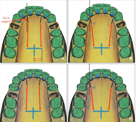
(5) Mo et al • Torque control in lingual orthodontics. interactions. In this study, the teeth, alveolar bone, and periodontal spaces were assumed to be isotropic and homogeneous linear elastic bodies, and the material properties of the elements were based on values for Young’s modulus and Poisson’s ratio, according to previous studies (Table 1).19-21 In the system studies, we assignedd the X-axis to the median-lateral direction, the Y-axis to the anterior-posterior direction, and the Z-axis to the coronal-apical direction. Furthermore, we defined +X as the left central incisor direction, +Y as the labial (anterior) direction, +Z as the apical direction, and the X - Y plane as the occlusal plane of the teeth. In all cases, we assumed no movement of the posterior teeth, since they received no force application. C-retractor To fabricate the C-retractor, a 0.9-mm stainless-steel round wire (this round wire is a 2-noded, 3D beam element that has 3 transitional and 3 rotational degrees. of freedom and can represent the bending characteristics of wires) was formed passively along the lingual surfaces of the upper anterior teeth. Afterwards, an additional wire was used to construct the lever arm hook, which was connected to the C-retractor by node sharing. The wire system was connected to stainless steel pads (tetrahedron solid element) by node sharing as well to complete the appliance (Figure 4). The C-retractor was adjoined to the Table 1. The mechanical properties of the materials used for each tissue type in the study Young’s modulus (Mpa). Poisson’s ratio. Periodontal ligament. 5.0E − 02. 0.49. Alveolar bone. 2.0E + 03. 0.30. Tooth. 2.0E + 04. 0.30. Stainless steel. 2.0E + 05. 0.30. Figure 5. Schematic representation of the coordinate system of the lingual biocreative therapy with the low lingual anterior retraction hook (LARH) at different positions. A, Condition 1: the LARHs, made of 0.9-mm round stainless steel, were placed between the upper central and lateral incisors with 6° of toe in angle. B, Condition 2: the LARHs were placed between the lateral incisors and canines with 15° of toe in angle. C, Condition 3: the LARHs were placed between the upper central and lateral incisors after second premolar extraction. D, Condition 4: the LARHs were placed between the lateral incisors and canines with 15° of toe in angle after second premolar extraction.. www.e-kjo.org. http://dx.doi.org/10.4041/kjod.2013.43.1.3. 7.
(6) Mo et al • Torque control in lingual orthodontics. Table 2. Comparison of the hook vertical height and retraction conditions relative to Z-axis displacement Tooth #11. Retraction condition. Hook vertical height (mm) 1. Root apex Incisal edge. 4. Root apex Incisal edge. 3. 4. 1.36E−02. 1.31E−02. −4.95E−02. −5.87E−02. −2.88E−02. −3.43E−02. 2.16E−02. 2.40E−02. 1.18E−02. 1.21E−02. −3.59E−02. −4.73E−02. −1.82E−02. −2.69E−02. 1.58E−02. 1.96E−02. 9.12E−03. 1.07E−02. Root apex. −1.51E−02. −3.11E−02. −2.99E−03. −1.63E−02. 10. Root apex. 7.66E−03. 1.30E−02. 5.21E−03. 8.40E−03. Incisal edge. 1.43E−02. −6.96E−03. 1.86E−02. −7.38E−04. 13 1. Root apex. −3.97E−03. 2.42E−03. −3.53E−04. 4.61E−03. Incisal edge. 5.50E−02. 2.95E−02. 4.81E−02. 2.30E−02. Root apex. 2.71E−02. 3.24E−02. 1.19E−02. 1.48E−02. −3.06E−02. −3.88E−02. −1.88E−02. −2.40E−02. 2.13E−02. 2.82E−02. 9.06E−03. 1.34E−02. −2.10E−02. −3.02E−02. −1.22E−02. −1.80E−02. Incisal edge 4. Root apex Incisal edge. 7. Root apex Incisal edge. 10. Root apex. 13. Root apex. Incisal edge Incisal edge #13. 2 2.70E−02. 7. Incisal edge. #12. 1 2.54E−02. 1. Root apex. 7 10 13. 2.22E−02. 5.10E−03. 1.13E−02. −1.81E−02. −3.17E−03. −9.55E−03. 2.75E−03. 1.30E−02. −7.68E−04. 8.19E−03. 9.04E−03. −1.60E−04. 1.02E−02. 2.85E−03. −1.27E−02. −1.08E−03. −8.86E−03. 3.11E−03. 3.39E−02. 2.67E−02. 2.85E−02. 2.16E−02. 4.26E−02. 5.05E−02. 1.85E−02. 2.26E−02. −4.19E−03. −1.13E−02. −4.84E−03. −1.04E−02. 3.43E−02. 4.18E−02. 1.63E−02. 1.82E−02. Cusp tip. 5.02E−04. −6.78E−03. 1.65E−02. −6.33E−03. Root apex. 2.29E−02. 2.92E−02. 8.83E−03. 1.18E−02. Cusp tip. 5.84E−03. −2.55E−04. 3.70E−03. −4.76E−04. Cusp tip 4. 1.37E−02 −8.66E−03. Root apex. Root apex. 6.97E−03. 1.04E−02. 9.18E−04. 2.18E−03. Cusp tip. 1.28E−02. 9.27E−03. 1.02E−02. 8.15E−03. −1.55E−02. −1.83E−02. −1.03E−02. −1.28E−02. 2.25E−02. 2.36E−02. 1.94E−02. 2.15E−02. Root apex Cusp tip. Positive figures mean tooth intrusion and negative figures mean extrusion. Condition 1, The lingual anterior retraction hooks (LARHs) were placed between the upper central incisors and lateral incisors 6° of toe in angle. Condition 2, The LARHs were placed between the lateral incisors and canines with 15°of toe in angle. Condition 3, The LARHs were placed between the upper central incisors and lateral incisors after second premolar extraction. Condition 4, The LARHs were placed between the lateral incisors and canines with 15°of toe in angle after second premolar extraction.. lingual surfaces of the upper anterior teeth at 5.5 mm apical to the incisal edge of the maxillary central incisor by node sharing. Four experimental conditions were used in this study, and were based on the teeth extracted and the placement of the LARHs. The maxillary first premolar extraction cases were conditions 1 and 2, while the second premolar extraction cases were conditions 3. 8. and 4. The LARH position between the maxillary central and lateral incisors comprised conditions 1 and 3, while LARH placement between the lateral incisors and canines made up conditions 2 and 4 (Figure 5). FEA and tooth displacement graphs The LARHs were constructed close to the surface of the. http://dx.doi.org/10.4041/kjod.2013.43.1.3. www.e-kjo.org.
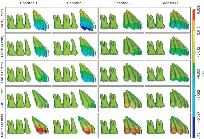
(7) Mo et al • Torque control in lingual orthodontics. Figure 6. Comparison of the effects of the different lengths and positions of the low lingual anterior retraction hooks (LARHs) in the C-retractor in the three dimensional finite element model. Tooth axies graph (incisor, midpoint of incisal edge to root apex; canine, cusp tip to root apex) magnified tooth displacement 70 times. Solid line means before displacement and a dotted line means after displacement (circles, central incisor; squares, lateral incisor; canine, triangles). Condition 1, The LARHs were placed between the upper central and lateral incisors after first premolar extraction. Condition 2, The LARHs were placed between the upper lateral incisors and canines after first premolar extraction. Condition 3, The LARHs were placed between the upper central and lateral incisors after second premolar extraction. Condition 4, The LARHs were placed between the upper lateral incisors and canines after second premolar extraction. palatal rugae, and the element analysis was implemented for each case using different vertical heights (1, 4, 7, 10, and 13 mm) for the LARHs. The vertical height was measured from the plane of the mesh-plate to the end of the hook perpendicular to the occlusal plane. In clinical studies, the retraction force was applied from the C-plate; however, in this FEA study, the C-plate model was not included in the analysis, and was therefore not fabricated. This reduced complications in the analysis.. www.e-kjo.org. http://dx.doi.org/10.4041/kjod.2013.43.1.3. Using the usual position and dimensions of the C-plate as a reference, the hooks extending laterally from the C-plate were laterally 8.2 mm from the mid-palatal suture, sagitally located between the upper first and second molar, and 12 mm apical to the common lingual bracket position. A retraction force of 200 g was applied to each side (Figures 4 and 5). The tooth displacement was marked by applying the X, Y, Z coordinates at the midpoint of the incisal. 9.
(8) Mo et al • Torque control in lingual orthodontics. Figure 7. Comparison of the vertical effects (Z-axis) of the different heights and positions of the low lingual anterior retraction hooks (LARHs) in the three dimensional finite element model. edges of #11 and #12, the cusp tip of #13, and the corresponding root tips. The FEA was performed using ANSYS 11 (Swanson Analysis System, Canonsburg, PA, USA), the universal finite element program, on an HP-XW6400 workstation (Hewlett-Packard Co., Palo Alto, CA, USA). This study was approved by Institutional Review Board of Yeouido St. Mary’s Hospital.. extrusion was greater for condition 2 than for condition 1 at the same LARH height. For condition 2, the incisal edge of #11 and the cusp tip of #13 were intruded at the LARH vertical heights of 13 and 10 mm, respectively. The results for conditions 3 and 4 were similar to those for conditions 1 and 2, respectively; however, the amount of tooth displacement under conditions 3 and 4 were reduced relative to conditions 1 and 2.. RESULTS. Tooth displacement pattern on the Y-axis For condition 1, a retraction force of 200 g resulted in lingual and uncontrolled tipping of the maxillary central incisor crown when the LARH vertical height was 1 mm (Table 3, Figures 6 and 8). Controlled tipping was observed at the LARH vertical heights of 4 and 7 mm, while bodily displacement and the occurrence of root retraction was noted at the LARH vertical heights of 10 and 13 mm. For condition 2, the degree of the lingual tipping of #11, #12, and #13 increased in comparison to condition 1 at the same LARH vertical height. For condition 2, the maxillary central incisors at the LARH vertical heights of 7 and 10 mm showed controlled. Tooth displacement pattern on the Z-axis Two hundred grams of retraction force was applied to the C-retractor hook under the 4 conditions described in the Materials and Methods section. The results of the relationship between the tooth displacement pattern on the Z-axis (the plus [+] and minus [−] symbols refer to intrusion and extrusion, respectively) and the vertical height of the LARH are shown in Table 2 and Figures 6 and 7. For condition 1, the incisal edge of #11 and the cusp tip of #13 were intruded using the LARH vertical heights of 10 and 4 mm, respectively. The degree of. 10. http://dx.doi.org/10.4041/kjod.2013.43.1.3. www.e-kjo.org.
(9) Mo et al • Torque control in lingual orthodontics. Table 3. Comparison of the hook vertical height and retraction conditions relative to Y-axis displacement Tooth. Hook vertical height (mm). #11. 1. Retraction condition 1 Root apex Incisal edge. 4. #12. 4. 3.18E−03. 1.25E−02. −9.10E−02. −9.37E−02. −5.38E−02. −5.25E−02. 1.04E−03. 1.72E−02. −5.42E−03. 7.00E−03. −7.65E−02. −8.12E−02. −4.53E−02. −4.63E−02. 7. Root apex. −1.45E−02. 6.39E−03. −1.83E−02. −7.94E−04. Incisal edge. −5.52E−02. −6.33E−02. −3.32E−02. −3.73E−02. 10. Root apex. −3.62E−02. −9.39E−03. −3.64E−02. −1.22E−02. Incisal edge. −2.49E−02. −3.61E−02. −1.59E−02. −2.38E−02. Root apex. 1. −6.58E−02. −3.28E−02. −6.08E−02. −2.92E−02. Incisal edge. 1.82E−02. 6.00E−03. 8.72E−03. −2.44E−03. Root apex. 1.74E−02. 2.72E−02. 5.99E−03. 1.41E−02. −8.38E−02. −1.01E−01. −4.62E−02. −5.43E−02. 6.70E−03. 1.94E−02. −1.74E−03. 8.69E−03. Incisal edge. −6.67E−02. −8.59E−02. −3.65E−02. −4.61E−02. Incisal edge 4 7. Root apex Root apex. −6.38E−03. 8.27E−03. −1.16E−02. 1.21E−03. Incisal edge. −4.34E−02. −6.37E−02. −2.29E−02. −3.43E−02. 10. Root apex. −2.45E−02. −7.98E−03. −2.57E−02. −9.69E−03. Incisal edge. −9.99E−03. −3.05E−02. −2.23E−03. −1.66E−02. 13. Root apex. −4.93E−02. −3.18E−02. −4.44E−02. −2.55E−02. 3.77E−02. 2.08E−02. 2.66E−02. 1.18E−02. Incisal edge #13. 3. 2.48E−02. Incisal edge. 13. Root apex. 2. 1.08E−02. 1. Root apex Cusp tip. 4. Root apex Cusp tip. 7. Root apex Cusp tip. 10 13. 2.27E−02. 2.77E−02. 8.54E−03. 1.28E−02. −8.29E−02. −1.12E−01. −4.31E−02. −5.75E−02. 1.47E−02. 1.82E−02. 3.51E−03. 6.11E−03. −6.33E−02. −9.25E−02. −3.24E−02. −4.68E−02. 4.71E−03. 4.88E−03. −2.81E−03. −3.23E−03. −3.75E−02. −6.53E−02. −1.81E−02. −3.15E−02. Root apex. −8.58E−03. −1.46E−02. −1.08E−02. −1.68E−02. Cusp tip. −3.03E−03. −2.47E−02. 1.59E−03. −8.57E−03. Root apex. −2.68E−02. −4.37E−02. −2.21E−02. −3.70E−02. 4.44E−02. 3.72E−02. 2.94E−02. 2.72E−02. Cusp tip. Positive figures mean tooth procline and negative figures mean retraction. Condition 1, The lingual anterior retraction hooks (LARHs) were placed between the upper central incisors and lateral incisors 6° of toe in angle. Condition 2, The LARHs of were placed between the lateral incisors and canines with 15°of toe in angle. Condition 3, The LARHs were placed between the upper central incisors and lateral incisors after second premolar extraction. Condition 4, The LARHs were placed between the lateral incisors and canines with 15°of toe in angle after second premolar extraction.. tipping, while actual root retraction was observed with the LARH vertical height of 13 mm. The pattern of tooth movement was similar between conditions 1 and 3, but bodily displacement for condition 3 was observed at a lower vertical height of 7 mm. Meanwhile, a similar pattern of tooth displacement was found between conditions 1 and 4, but bodily movement in condition. www.e-kjo.org. http://dx.doi.org/10.4041/kjod.2013.43.1.3. 4 was observed only when the vertical height was more than 10 mm.. DISCUSSION In lingual orthodontic treatment, the attachment and re moval of lingual brackets are technique sensitive,. 11.
(10) Mo et al • Torque control in lingual orthodontics. Figure 8. Comparison of the sagittal effects (Y-axis) of the different heights and positions of the low lingual anterior retraction hooks (LARHs) in the three dimensional finite element model. and thus challenging and time consuming. Because of these issues, these proceudres may involve a complex and expensive set-up process. Moreover, routine adjustments and archwire fabrication require expertise, experience, and technical skill. As a result of these challenges, some clinicians choose expensive technology to facilitate the process. For instance, in cases in which the treatment of anterior protrusion requires maximum anchorage, complicated overlay archwires and/or miniimplant anchorage have been recommended to achieve controlled 3D tooth movement.22 The lingual biocreative therapy applied in this study is a method to retract the anterior dental segment using forces between the C-retractor and the C-plate. The biomechanical premise underlying segmental orthodontics is adapted from one of Burstone’s protocols,23 but differs in that the force is applied to a segment from a skeletal anchor with no connection to the posterior teeth. Extended lever arms have been used in conventional lingual orthodontics for retraction against mini-screw-anchors, but torque loss is a common side effect due to slot play within the appliance as well as flexibility of the archwire. Biocreative therapy with the C-retractor eliminates these. 12. side effects, because the anterior segment is bonded as a unit with a rigidly constructed device. Furthermore, retraction control is in the hands of the clinician, since controlled bodily displacement, tipping, and root retraction is possible through altering the vertical height of the LARH.24,25 The results of the current study are similar to those of the FEA study of Jang et al.,26 which used a modified C-retractor and various miniscrew positions. In that study, the optimal choice for vertical height of the LARH was found to be related to the goals for retraction (i.e. , controlled tipping, bodily displacement, root retraction). The device was bonded to the lingual surfaces of the upper 6 or 8 anterior teeth, and retraction was implemented by applying a closed NiTi coil spring between the extension hook of the C-plate and the LARH of the C-retractor. In the current study, 3D tooth displacement was controlled by varying the vertical height of the LARH. Our results were different from those of a previous clinical study to control torque,27,28 as well as the study by Mo et al.,29 which attempted 3D tooth movement through the control of intrusion and retraction in a labial treatment method. The latter. http://dx.doi.org/10.4041/kjod.2013.43.1.3. www.e-kjo.org.
(11) Mo et al • Torque control in lingual orthodontics. Figure 9. A, When the lingual anterior retraction hook is located distal to the central incisors (condition 1 or 3). B, Part of the extraction space is closed by C-retractor. C, The canine can be segmented from the C-retractor for detailing. D, Incisors and canines are decrowded with conventional bracket system. study showed differences between the control of the incisors and canines, but found that only variation of the vertical height of the LARH provided the desired 3D control during retraction of the anterior teeth.29 One of the potential reasons for this difference between the previous report and the current one may be the rigidity afforded by the C-retractor. The 0.9-mm wire is much stiffer than a standard archwire placed in conventional lingual brackets. Future studies may show this rigid C-retractor to be valuable when applying heavy retraction forces, as in the case of perisegmental corticotomy for inducing rapid tooth movement.13,30 In the current study, the retraction pattern depended on the position of the LARH. Although both positions met the requirements of controlling the upper incisor axes and preventing deepening of the bite, the position for conditions 1 and 3 (between the maxillary central and lateral incisors) had more significant treatment effects for the same vertical height than that of conditions 2 and 4 (between the lateral incisors and the canines). One advantage of using the LARH position in conditions 1 or 3 is that the canine can be segmented from the C-retractor, allowing detailing of the canine while still retaining incisor retraction with the C-plate (Figure 9). Therefore, we recommend that as a rule of thumb, the LARH should be placed distal to the central incisors rather than distal to the lateral incisors. This study examined the initial displacement due to. www.e-kjo.org. http://dx.doi.org/10.4041/kjod.2013.43.1.3. orthodontic forces, using the FE method. Hence, further studies on the clinical long-term effects, the retraction pattern, and the risk of root resorption for lingual biocreative therapy using the C-retractor and C-plate will be needed. In addition, we anticipate further studies on the design and treatment effects of C-retractors in asymmetrical premolar extraction cases.. CONCLUSION The following conclusions can be made on the basis of the findings in this study: 1. FE studies have demonstrated that variations in the vertical height of the LARH affect the vector of the retraction force and produce measurable effects on the inclination and vertical position of the anterior teeth during anterior retraction. 2. The LARH can be placed between the central and lateral incisors or between the lateral incisors and canines. Placement distal to the central incisors was considered preferable because the treatment effects were better. If the LARH is distal to the lateral incisors, a vertically higher hook is necessary to achieve bodily displacement.. REFERENCES 1. Ye L, Kula KS. Status of lingual orthodontics. World. 13.
(12) Mo et al • Torque control in lingual orthodontics. J Orthod 2006;7:361-8. 2. Takemoto K, Scuzzo G. The straight-wire concept in lingual orthodontics. J Clin Orthod 2001;35:46-52. 3. Gorman CJ Jr. Lingual orthodontics. Dent Clin North Am 1997;41:111-25. 4. Hong RK, Sohn HW. Update on the Fujita lingual bracket. J Clin Orthod 1999;33:136-42. 5. Wiechmann D, Gerss J, Stamm T, Hohoff A. Prediction of oral discomfort and dysfunction in lingual orthodontics: a preliminary report. Am J Orthod Dentofacial Orthop 2008;133:359-64. 6. Miyawaki S, Yasuhara M, Koh Y. Discomfort caused by bonded lingual orthodontic appliances in adult patients as examined by retrospective questionnaire. Am J Orthod Dentofacial Orthop 1999;115:83-8. 7. Stamm T, Hohoff A, Ehmer U. A subjective comparison of two lingual bracket systems. Eur J Orthod 2005;27:420-6. 8. Cacciafesta V, Sfondrini MF. One-appointment correction of a scissor bite with 2D lingual brackets and fiber-reinforced composites. J Clin Orthod 2006; 40:409-11. 9. Park HS. A miniscrew-assisted transpalatal arch for use in lingual orthodontics. J Clin Orthod 2006; 40:12-6. 10. Hong RK, Heo JM, Ha YK. Lever-arm and miniimplant system for anterior torque control during retraction in lingual orthodontic treatment. Angle Orthod 2005;75:129-41. 11. Kim KH, Lee KJ, Cha JY, Park YC. Finite element analysis of effectiveness of lever arm in lingual sliding mechanics. Korean J Orthod 2011;41:324-36. 12. Chung KR, Jeong DM, Park HJ, Kim SH, Nelson G. Severe bidentoalveolar protrusion treated with lingual biocreative therapy using palatal miniplate. Korean J Orthod 2010;40:276-87. 13. Chung KR, Kook YA, Kim SH, Mo SS, Jung JA. Class II malocclusion treated by combining a lingual retractor and a palatal plate. Am J Orthod Dentofacial Orthop 2008;133:112-23. 14. Kim S, Park Y, Chung K. Severe anterior open bite malocclusion with multiple odontoma treated by C-lingual retractor and horseshoe mechanics. Angle Orthod 2003;73:206-12. 15. Kim JS, Kim SH, Kook YA, Chung KR, Nelson G. Analysis of lingual en masse retraction combining a C-lingual retractor and a palatal plate. Angle Orthod 2011;81:662-9. 16. Andrews LF. The six keys to normal occlusion. Am J Orthod 1972;62:296-309. 17. Germane N, Bentley BE Jr, Isaacson RJ. Three biologic variables modifying faciolingual tooth angulation by straight-wire appliances. Am J Orthod Dentofacial Orthop 1989;96:312-9.. 14. 18. Coolidge ED. The thickness of the human periodontal membrane. J Am Dent Assoc, Dent Cosmos 1937;24:1260-70. 19. Tanne K, Sakuda M, Burstone CJ. Three-dimensional finite element analysis for stress in the periodontal tissue by orthodontic forces. Am J Orthod Dentofacial Orthop 1987;92:499-505. 20. Poppe M, Bourauel C, Jäger A. Determination of the elasticity parameters of the human periodontal ligament and the location of the center of resistance of single-rooted teeth a study of autopsy specimens and their conversion into finite element models. J Orofac Orthop 2002;63:358-70. 21. Kim MJ, Park SH, Kim HS, Mo SS, Sung SJ, Jang GW, et al. Effects of orthodontic mini-implant posi tion in the dragon helix appliance on tooth displacement and stress distribution: a three-dimensional finite element analysis. Korean J Orthod 2011; 41:191-9. 22. Bae SM, Park HS, Kyung HM, Kwon OW, Sung JH. Clinical application of micro-implant anchorage. J Clin Orthod 2002;36:298-302. 23. Burstone CJ. The segmented arch approach to space closure. Am J Orthod 1982;82:361-78. 24. Sung SJ, Kim IT, Kook YA, Chun YS, Kim SH, Mo SS. Finite-element analysis of the shift in center of resistance of the maxillary dentition in relation to alveolar bone loss. Korean J Orthod 2009;39:278-88. 25. Jeong GM, Sung SJ, Lee KJ, Chun YS, Mo SS. Finite-element investigation of the center of resistance of the maxillary dentition. Korean J Orthod 2009;39:83-94. 26. Jang HJ, Roh WJ, Joo BH, Park KH, Kim SJ, Park YG. Locating the center of resistance of maxillary anterior teeth retracted by Double J Retractor with palatal miniscrews. Angle Orthod 2010;80:1023-8. 27. Park YC, Choi YJ, Choi NC, Lee JS. Esthetic segmental retraction of maxillary anterior teeth with a palatal appliance and orthodontic mini-implants. Am J Orthod Dentofacial Orthop 2007;131:537-44. 28. Kim SH, Hwang YS, Ferreira A, Chung KR. Analysis of temporary skeletal anchorage devices used for enmasse retraction: a preliminary study. Am J Orthod Dentofacial Orthop 2009;136:268-76. 29. Mo SS, Kim SH, Sung SJ, Chung KR, Chun YS, Kook YA, et al. Factors controlling anterior torque during C-implant-dependent en-masse retraction without posterior appliances. Am J Orthod Dentofacial Orthop 2011;140:72-80. 30. Kim HS, Lee YJ, Park YG, Chung KR, Kang YG, Choo H, et al. Histologic assessment of the biological effects after speedy surgical orthodontics in a beagle animal model: a preliminary study. Korean J Orthod 2011;41:361-70.. http://dx.doi.org/10.4041/kjod.2013.43.1.3. www.e-kjo.org.
(13)
수치

관련 문서
Torque & power delivered by hydraulic motors Torque & power delivered by hydraulic motors Performance of hydraulic motors.. Comparison of variable performance
The purposes of the present study are to evaluate the clinical outcomes and radiological outcomes including bone fusion and subsidence that occurred after
On 10 May 2019, Aux feed system operation and manual nuclear reactor trip in HanBit #1 as a cause of withdrawing control rod during reactor characteristic test,
In addition to an integrated control system of state obligation, the government should expand the control boundary of state obligation, so that it, putting
During the term of this Agreement, Manufacturer shall not, either directly or indirectly, sell the products in the Territory without the prior consent of distributor...
(4) After a certain period of tightening time with tightening torque, Z-axis and rotating axis return in positioning control mode to the retracted
Without limiting the generality of Article 14(1), no trust governed by the laws of the DIFC and no disposition of property to be held in trust that is valid under the laws of the
1 John Owen, Justification by Faith Alone, in The Works of John Owen, ed. John Bolt, trans. Scott Clark, "Do This and Live: Christ's Active Obedience as the
