Ⅰ. Introduction
In the continuous search for improvement of endodontic instruments, the greatest innovation introduced in the last decade was the development of nickel-titanium (Ni-Ti) rotary files. The Ni-Ti rotary files exhibit super-elasticity and can prepare root canals with a suitable taper and flow compared to stainless steel hand files and with less apical aberra-
tions.1-3) Despite the evident advantages, the Ni-Ti rotary files can undergo unexpected fracture as a result of shear or fatigue failure in curved root canals, with the latter being implicated in more than one-third of those instruments fractured clinically.4-6) Many factors have been implicated in the fatigue fracture of the Ni-Ti rotary files. Of these, the instru- ment designs and the cross-sectional area can affect the magnitudes of stress and strain when subject to torsion or bending.7-9) Recently, Ni-Ti rotary instru- ments are available in a variety of cross-sectional shapes such as a triangle (ProFile, K3, and HeroShaper), modified rectangle (NRT and Mtwo), and pentagon (Alpha System). To date, there has been few studies on how Ni-Ti rotary instruments This study aimed to assess the influence of different cross-sectional area on the cyclic fatigue fracture of Ni-Ti rotary files using a fatigue tester incorporating cyclical axial movement. Six brands of Ni-Ti rotary files (ISO 30 size with .04 taper) of 10 each were tested: Alpha system (KOMET), HeroShaper (MicroMega), K3 (SybronEndo), Mtwo (VDW), NRT (Mani), and ProFile (Dentsply). A fatigue-tester (Denbotix) was designed to allow cyclic tension and compressive stress on the tip of the instrument. Each file was mounted on a torque controlled motor (Aseptico) using a 1:20 reduction contra-angle and was rotated at 300 rpm with a continuous, 6 mm axial oscillating motion inside an artificial steel canal. The canal had a 60�angle and a 5 mm radius of curvature. Instrument fracture was visually detected and the time until fracture was recorded by a digital stop watch. The data were analyzed statistically.
Fractographic analysis of all fractured surfaces was performed to determine the fracture modes using a scanning electron microscope. Cross-sectional area at 3 mm from the tip of 3 unused Ni-Ti instruments for each group was calculated using Image-Pro Plus (Imagej 1.34n, NIH). Results showed that NRT and ProFile had significantly longer time to fracture compared to the other groups (p < .05). The cross-sectional area was not significantly associated with fatigue resistance. Fractographycally, all fractured surfaces demonstrated a combination of ductile and brittle fracture. In conclusion, there was no significant relation- ship between fatigue resistance and the cross-sectional area of Ni-Ti instruments under experimental con- ditions. [J Kor Acad Cons Dent 34(5):424-429, 2009]
Key words: artificial steel canal, cross-sectional area, fatigue resistance, fractographic analysis
-Received 2009.9.1., revised 2009.9.11., accepted 2009.9.11.- ABSTRACT
Corresponding Author: KKeeee--YYeeoonn KKuumm
Department of Conservative Dentistry, Dental Research Institute, BK 21 program, School of Dentistry, Seoul National University 28-2 Yeongun-Dong, Jongno-Gu, Seoul, Korea Tel :+82-2-2072-2656 Fax : +82-2-764-3514 Email : [email protected]
EFFECT OF CROSS-SECTIONAL AREA OF 6 NICKEL-TITANIUM ROTARY INSTRUMENTS ON THE FATIGUE FRACTURE UNDER CYCLIC FLEXURAL STRESS: A FRACTOGRAPHIC ANALYSIS
Soo-Youn Hwang1, So-Ram Oh1, Yoon Lee1,3, Sang-Min Lim1, Kee-Yeon Kum1,2*
1Department of Conservative Dentistry, 2Dental Research Institute, BK21 Program, School of Dentistry, Seoul National University,
3Wonkwang University
with different cross-sectional shapes behave when subjected to rotational-bending, a deformation mode similar to an engine-file rotating in a curved root canal, but the effect of cross-sectional shapes on the cyclic fatigue fracture is still controversial.7-12)Several studies have been performed to evaluate the cyclic fatigue in a dynamic model incorporating axial oscil- lating motion.13,14) This not only provides a better clinical simulation than the static model, but these studies also demonstrated that the axial (pecking) motion significantly lengthens the life span of the rotary files.15)Fractography can be broadly defined as the science of observing, measuring and interpreting a fractured surface topography. When material fail- ure involves actual breakage, fractography can be used to identify the fracture origin, the direction of crack propagation, the failure mechanism, materials defects, and the nature of the stresses.16)
Therefore, this in vitro study aimed to assess the influence of different cross-sectional shapes of Ni-Ti rotary files on the flexural fatigue fracture in a dynamic model and to determine the fracture pat- terns of broken file surfaces through a fractographic analysis using a scanning electron microscope.
Ⅱ. Materials and methods
Six experimental groups were allocated according to 6 brands of Ni-Ti rotary instruments of 10 each. The instruments tested were Alpha System (KOMET, Culver, Germany), HeroShaper (Micro-Mega, Besanc¸ on, France), K3 (SybronEndo, CA, USA), Mtwo (VDW, Munich, Germany), NRT (MANI, Utsunomiya, Japan), and ProFile (Dentsply,
Ballaigues, Switzerland). All the instruments were
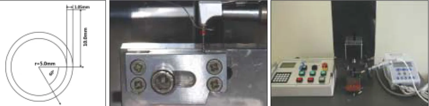
#30/.04 in size and 25 mm in length. Fatigue testing was carried out in a fatigue tester (Denbotix, Bucheon, Korea) that allows the files to rotate freely inside an artificial stainless-steel canal and also allows the handpiece to move vertically (Figure 1).
Each file was mounted on an electric motor (Aseptico, WA, USA) using a 1:20 reduction contra- angle handpiece. The instrument was rotated at 300rpm inside an artificial canal. An artificial canal was made out of stainless steel with an inner diame- ter of 1.05 mm, 10 mm in length, angle of 60�, and a radius of curvature of 5 mm. A continuous, 6 mm axial oscillating motion was applied at 0.5 cycles per second to simulate a clinical pecking motion. The apparatus can control the pecking distance, oscilla- tion speed and set starting and ending point. The starting point was set at the apical end of the canal
During the test, the artificial canal was filled with RC Prep (Premier Dental Co., PA, USA) to reduce the instrument’s friction against the canal wall and heat generation. Instrument fracture was visually detected and the time until fracture was recorded using a digital stop watch. The mean and standard deviation values of the fracture time were calculated for each group. Using the SPSS statistical package version 12 (SPSS Inc., Chicago, IL, USA), the differ- ence among the instruments as to their fatigue resis- tance was analyzed using one way analysis of the variance (ANOVA). Tukey post hoc analysis was used to identify the specific groups that showed sig- nificant difference. The level of significance was set at 5%.
For fractographic analysis, all fractured files from
Figure 1.Schematic diagrams and pictures of an artificial canal and a fatigue tester (Denbotix).
each group were photographed using a scanning elec- tron microscope (JSM840A, JOEL, Tokyo, Japan) to determine the modes and patterns of fracture at magnifications of ×200, ×500, and ×1000. In addi- tion, the cross-sectional area of 6 brands of Ni-Ti instruments was determined using SEM photographs as follows. Three new Ni-Ti instruments for each group was embedded in resin and cut at a 3.0 mm from the tip with an ISOmet 11-1180 low-speed saw (Buehler, Lake Bluff, Ill, USA). Then, the specimens were cleaned in an ultrasonic water bath for 15 min.
The sections were examined by SEM at a magnifica- tion of ×200. The mean cross-sectional area of each file was calculated using Image-Pro Plus software (Imagej 1.34n, NIH, Bethesda, MD, USA). The cor- relation between the mean cross sectional area and the mean time to fracture of each group was exam- ined using linear regression analysis with statistical significance set to α=0.05.
Ⅲ. Results
1. FT (fracture time) measurements
The mean time to fracture for 6 experimental groups was shown in figure 2. For the mean time to fracture, NRT group gave the best values. The mean time to fracture of NRT and ProFile were significant- ly higher than those of the other groups (p < .05), but there was no significant difference between NRT and ProFile. Also, there was no significant difference
among Mtwo, K3, Heroshaper, and Alpha System.
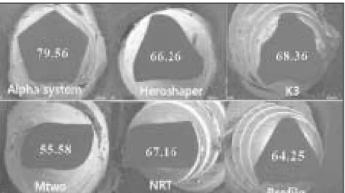
Different cross-sectional shapes of 6 Ni-Ti rotary instruments and the calculated cross-sectional areas are presented in figure 3. The cross-sectional area of Mtwo file was the smallest, while that of Alpha sys- tem was the biggest. The Spearman correlation coef- ficient was calculated to examine the correlation between time to fracture and the calculated cross- sectional area. The correlation coefficient (r) was 0.035, which revealed no significant relationship between time to fracture and the cross-sectional area of Ni-Ti rotary files tested.
2. Fractographic analysis on the fractured surfaces
Low-magnification SEM photographs showed smooth area of brittle fracture to be the main failure mode at the periphery (Figure 4a), which typically led to a large central region of catastrophic ductile fracture in all fractured samples. The central area of ductile fracture was typically characterized by microvoid formation and dimpling (cup-and-cone fracture, Figure 4b, white arrow). On the contrary, the smooth region at the periphery showed a pres- ence of micro-crack at flute face (NRT, X500, Fig.4c, white arrow), which was considered to act as a trig- ger point of brittle fracture, and clusters of multiple linear striations (K3, ×1000, figure 4d, white arrow).
In addition, the fracture planes at the peripheral bor- der of the cross-section were at different levels from the main fracture plane in most samples.
Figure 2.Standard deviation and mean values of time to fracture of 6 Ni-Ti files (second).
* Statistically significant (p < .05).
Figure 3. SEM views of cross-sectional shapes of 6 Ni-Ti rotary instruments and the calculated cross-sectional area at 3 mm from the tip(×200).
second
2500
2000
1500
1000
500
0
ProFile Mtwo K3 Heroshaper NRT Alphasystem
Ⅳ. Discussion
Many manufacturers have developed and designed new Ni-Ti rotary instruments that have different fea- tures, such as various cross-sectional shapes, pitch- es, helix, and tips. The fatigue resistance of endodon- tic files made of same material and same dimension (size and taper) is entirely dependent on instrument designs (cross-sectional area, pitch, helix, radial land, and/or spirals) and the cross-sectional area is closely associated with file flexibility (stiffness).12) Therefore, this study compared the cyclic fatigue resistance for 6 Ni-Ti rotary instruments with differ- ent cross-sectional configurations. A previous study by Scha¨fer et al.17) demonstrated that Ni-Ti rotary instruments with small cross-sectional area showed better results in terms of fatigue resistance. Turpin et al7) calculated the cross-sectional areas of triple- helix (Hero) and triple-U files (ProFile) and com- pared bending stresses in these 2 instruments. For identical working diameters, the cross-sectional area of the triple-helix (Hero) was found to be approxi- mately 30% greater than that of the triple-U shaped ProFile. The greater cross-sectional area determined a lower flexibility of the Hero file compared to ProFile, which can explain the poor fatigue resistance in their study. Likewise, Alpha System was more vulnerable to cyclic fatigue due to its large cross-sec-
tional area. Alpha System has five-edged (pentagon) cross-section and its cross-sectional area was the largest among 6 experimental groups. The present result, however, was not consistent with that of Turpin et al.7) and Scha¨fer et al.17) In other words, although Mtwo has the smallest cross-sectional area among the 6 Ni-Ti files tested, Mtwo showed the lowest value of fatigue resistance. A possible expla- nation might be that Mtwo instrument has a lower number of spirals per unit length. The fewer the spi- rals a flute has per unit length around the shaft of a file, the more it resists deformation but at the same time the more rigid it becomes.18)
On the contrary, Yao et al19) showed that K3 file was more resistant to cyclic fatigue than ProFile although K3 has larger cross-sectional area than ProFile. The authors explained that it may be related to the overall design of the K3 file, that is, the vari- able core diameter. Tripi et al.20) also demonstrated in their study that the variable core diameter and the presence of radial lands could explain the high fatigue resistance of K3 instruments. However, the present study showed that the fatigue resistance of K3 instrument was lower than that of ProFile which has a smaller cross-sectional area. This result is con- sistent with those of the previous studies.11,12) Therefore, more controlled studies regarding the effect of instrument designs on the fatigue fracture Figure 4.A photograph of fractured surface of NRT instrument (A, × 200) and the magnified view (round circle) showing the presence of micro-crack at lateral surface (C, white arrow, ×500) near the separated tip region. A photograph of fractured K3 instrument showing dimples at central area (B, white arrow, ×500). Evidence of brittle fracture is present as reflected by the multiple linear striations of on the peripheral fractured surface of K3 instrument (D, white arrow, ×1000).
are necessary.
An interesting finding in the present study was that NRT file showed the best value of fatigue resis- tance although the cross-sectional area was not the smallest. This finding is in agreement with the find- ing of other authors that Ni-Ti instruments with a triangular-based cross-sectional shapes (ProFile) dis- played a higher bending load than those that rectan- gular-based cross-sectional shapes (NRT).21) The authors contributed the high flexibility of NRT to the additional heat treatment during the manufacturing process. A previous study also suggested that rectan- gular shape can allow improvement of file flexibili- ty.22)
In conclusion, the cross-sectional area is not a determining factor affecting the fatigue resistance of Ni-Ti rotary file. In addition, NRT and ProFile sys- tem can be useful for safe instrumentation in curved root canals in the aspects of fatigue resistance.
References
1. Esposito PT, Cunningham CJ. A comparison of canal preparation with nickel-titanium and stainless steel instruments. J Endod 21:173-176, 1995.
2. Peters OA. Current challenges and concepts in the preparation of root canal systems: a review. J Endod 30:559-567, 2004.
3. Kosa DA, Marshall G, Baumgartner JC. An analysis of canal centering using mechanical instrumentation techniques.J Endod 25:441-5, 1999.
4. Bahia MGA, Melo MCC, Buono VTL. Influence of sim- ulated clinical use on the torsional behavior of nickel- titanium rotary endodontic instruments. Oral Surg Oral Med Oral Pathol Oral Radiol Endod 101: 675- 680, 2006.
5. Pruett JP, Clement DJ, Carnes DL. Cyclic fatigue test- ing of nickel-titanium endodontic instruments. J Endod 23:77-85, 1997.
6. Sattapan B, Nervo GJ, Palamara JEA, Messer HH.
Defects in rotary nickel-titanium files after clinical use. J Endod 26: 161-5, 2000.
7. Turpin YL, Chagneau F, Vulcain JM. Impact of two theoretical cross-sections on torsional and bending stresses of nickel-titanium root canal instrument mod- els. J Endod 26: 414-7, 2000.
8. Xu X, Zheng Y, Eng D. Comparative study of torsional and bending properties for six models of nickel-titani- um root canal instruments with different cross-sec- tions. J Endod 32:372-375, 2006.
9. Berutti E, Chiandussi G, Gaviglio I, Ibba A.
Comparative analysis of torsional and bending stresses in two mathematical models of nickel-titanium rotary instruments: ProTaper versus ProFile. J Endod 29:
15-9, 2003.
10. Cheung GS, Darvell BW. Low-cycle fatigue of Ni-Ti rotary instruments of various cross-sectional shapes.
Int Endod J 40: 626-632. 2007.
11. Shin YM, Kim ES, Kim KM, Kum KY. Effect of surface defects and cross-sectional configurations on the fatigue fracture of Ni-Ti rotary files in a dynamic model. J Kor Cons Dent 29:267-272, 2004.
12. Kim JK, Kum KY, Kim ES. Comparative study on mor- phology of cross-section and cyclic fatigue test with dif- ferent rotary Ni-Ti files and handling methods. J Kor Cons Dent 31:96-102, 2006.
13. Haikel Y, Serfaty R, Bateman G, Senger B, Alleman C.
Dynamic and cyclic fatigue of engine-driven rotary nickel-titanium endodontic instruments. J Endod 25:
434-440, 1999.
14. Li UM, Lee BS, Shih CT, Lan WH, Lin CP. Cyclic fatigue of endodontic nickel titanium rotary instru- ments: Static and dynamic tests. J Endod 28:448-51, 2002.
15. Dederich DN, Zakariasen KL. The effects of cyclical axial motion on rotary endodontic instrument fatigue.
Oral Surg Oral Med Oral Pathol 61:192-6, 1986.
16. Dieter GE. Mechanical metallurgy, 3rd ed. New York:
McGraw-Hill, pp.119, 138,185-8, 382-7, 394, 1986.
17. Scha¨fer E, Dzepina A, Danesh G. Bending properties of rotary nickel-titanium instruments. Oral Surg Oral Med Oral Pathol Oral Radiol Endod 96:757-63, 2003.
18. Ruddle CL. Nickel-titanium rotary systems: review of existing instruments and geometries. Dent Today 19:86-95, 2000.
19. Yao JH, Schwartz SA, Beeson TJ. Cyclic fatigue of three types of rotary nickel-titanium files in a dynamic model. J Endod 32:55-65, 2006.
20. Tripi TR, Bonaccorso A, Condorelli GG. Cyclic fatigue of different nickel-titanium endodontic rotary instru- ments. Oral Surg Oral Med Oral Pathol Oral radiol Endod 102:e106-e114, 2006.
21. Hayashi Y, Yoneyama T, Yahata Y, Suda K. Phase transformation behavior and bending properties of hybrid nickel-titanium rotary endodontic instruments.
Int Endod J 40; 247-253, 2007.
22. Ku JH, Chang HS, Jang SW, Min KS. The instrument- centering ability of four nickel-titanium instruments in simulated curved root canals. J Kor Cons Dent 31:113- 8, 2006.
국문초록
반복 굽힘 스트레스 하에서 전동식 니켈-티타늄 파일의 단면적의 크기가 피로파절에 미치는 영향 : 파절역학 분석
황수연1∙오소람1∙이 윤1,3∙임상민1∙금기연1,2*
서울대학교 치의학 전문대학원1치과보존학교실, 2치의학연구소, BK 21 Program
3원광대학교 치과보존학교실
본 연구의 목적은 니켈 티타늄 전동파일의 피로 파절에 파일의 단면 형태가 미치는 영향을 평가하고자 하였다. 6 종의 ProFile (Dentsply), Mtwo (VDW), K3 (SybronEndo), HeroShaper (MicroMega), NRT (Mani), Alpha sys- tem (KOMET) 니켈-티타늄 전동 파일(ISO 30 size/.04 taper)을 각 10개씩 실험군으로 배정하고 실험을 진행하였 다. 니켈 티타늄 전동파일에 반복적인 장력과 압축력을 재현시킬 수 있는 피로파절 실험기(Denbotix)와 연결된 토크 조 절 전동모터(Aseptico)에 각 군의 파일을 연결하여 300rpm 속도로 만곡도가 60도이고 5mm 의 반경을 가진 인공 금 속 근관 내를 6 mm pecking depth 로 작동시켰다. 각 파일의 파절시간을 측정하고 통계 분석하여 유의성을 분석하였 으며, 각 군의 파절된 모든 파일의 파절면을 주사전자현미경을 이용한 fractographic analysis를 통해 파절 역학을 규 명하였다. 또한 각 군에서 3 개의 사용하지 않은 새 파일을 clear resin 에 매몰하고 tip에서부터 3mm 지점을 횡절단하 여 Image-Pro Plus (Imagej 1.34n, NIH) 소프트웨어로 절단면의 단면적을 측정하고 단면적의 크기와 피로 파절과의 상관성도 평가하였다. 실험 결과 NRT와 ProFile이 다른 실험군에 비해서 유의성 있게 높은 피로 파절 저항성을 보였다 (P < .05). 또한 파일의 단면적은 피로파절 저항성과 통계학적인 유의성은 보이지 않았다. Fractographic analysis 결 과 모든 시편에서 파절면은 ductile fracture와 brittle fracture가 혼재된 양상으로 나타났다. 결론적으로 니켈 티타늄 전동 파일의 단면적의 크기는 피로파절 저항과는 상관성이 적었다.
주요단어 : 인공 금속근관, 단면형태, 피로파절 저항성, 파절역학 분석