http://dx.doi.org/10.5369/JSST.2020.29.2.75 pISSN 1225-5475/eISSN 2093-7563
Flicker-free Visible Light Communication Using Three-level RZ Modulation
Seong-Ho Lee
+Abstract
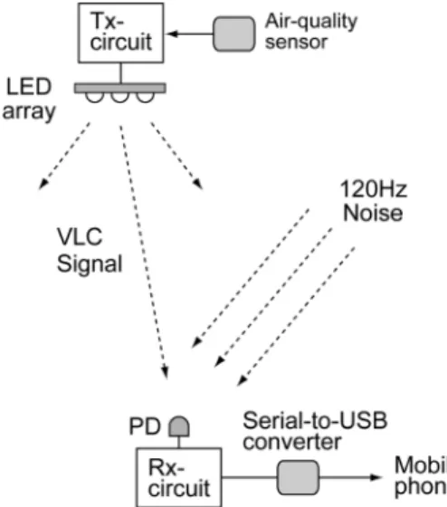
We introduce a new visible light communication (VLC) method in which three-level return-to-zero (RZ) modulation is used for flicker-free transmission. In the VLC transmitter, the three-level RZ modulation ensures that the average optical power is constant; thus, a flicker-free light-emitting diode (LED) light is achieved. In the VLC receiver, a resistor–capacitor high-pass filter is used for generating spike signals, which are used for data recovery while eliminating the 120 Hz optical noise from adjacent lighting lamps. In transmission experiments, we applied this method for wireless transmission of an air quality sensor message using the visible light of an LED array.
This configuration is useful for the construction of indoor wireless sensor networks for air pollution monitoring using LED lights.
Keywords: Visible light communication, Three-level RZ modulation, LED, Flicker-free, RC-HPF, Spike signal, Noise
1. INTRODUCTION
Light-emitting diodes (LEDs) are extensively used as the primary light source in various areas, such as indoor lighting in offices and homes, security lighting for streets, and car lighting.
When compared to the traditional fluorescent lamps or incandescent lamps, LEDs demonstrate several advantages, including high power efficiency, high mechanical strength, and small size. In addition, the illumination of LEDs can be easily controlled by changing the injection current and the response is significantly fast, i.e., within a few microseconds. By utilizing the intrinsic high-speed response characteristics of the LEDs, visible light communication (VLC) technology was developed, in which communication and lighting functions are performed simultaneously [1-6]. In VLC, an LED light is generally used as the carrier for wireless data transmission for short distances and the signal light from the transmitter is directly detected by the photodetector through free space. Visible light and radio frequency do not interfere with each other; thus, VLC can be a good transmission method in places where electromagnetic
interference should be avoided or where high security is required to prevent eavesdropping [7].
Because the LED light is used for both illumination and communication in VLC, the systems should be designed such that illumination and communication do not affect each other. For example, the LED illumination can be changed unintentionally during communication owing to the variation in the average optical power of the LED. This phenomenon may result in LED light flicker, which is a very unstable lighting condition; thus, appropriate methods should be provided to eliminate LED flicker.
In the VLC receiver, the photodiodes (PDs) may be exposed to unwanted light from adjacent lighting lamps while it receives the signal from the transmitter. Incandescent lamps, fluorescent lamps, or other LED lamps, which are powered by a 60 Hz power line, generally radiate an optical noise of 120 Hz, which corresponds to twice the power-line frequency. Because the optical noise is also in the visible spectrum, it is detected by the VLC receiver. Consequently, the 120 Hz noise is induced in the VLC receiver while receiving the signal light transmitted from the VLC transmitter. If the optical noise intensity is not negligible, it may interfere with the signal and can cause errors during data transmission, especially in baseband VLC systems. Thus, a noise prevention method should also be considered in the system design. In baseband VLC systems, Manchester code modulation and pulse-position modulation are generally used for preventing LED flicker because they maintain the average optical power as constant in the transmitter. These schemes require an additional channel for clock transmission to recover the data in the receiver [5, 8].
Department of Electronics and IT Media Engineering, Seoul National University of Science and Technology, 232 Gongneung-ro, Nowon-gu, Seoul, 01811, Korea
+
Corresponding author: [email protected] (Received :Oct. 16, 2019, Accepted : Feb. 04, 2020)
This is an Open Access article distributed under the terms of the Creative Commons Attribution Non-Commercial License(https://creativecommons.org/
licenses/by-nc/3.0/) which permits unrestricted non-commercial use, distribution,
and reproduction in any medium, provided the original work is properly cited.
subcarrier; thus, the system design may be more complex to implement than that of the baseband systems.
In this paper, we introduce a new baseband transmission method in which three-level return-to-zero (RZ) modulation is used for preventing the flicker of LED lights; further, spike detection is used for the 120 Hz noise prevention. In the VLC transmitter, three field-effect transistors (FETs) are used for supplying LED current, in which two FETs are for the three-level LED modulation and another FET is for controlling the DC optical power. The total current of the two FETs constitute a three- level RZ modulation signal, in which the average optical power of the LED light is maintained constant; thus, the flicker is eliminated. In the VLC receiver, a resistor–capacitor high-pass filter (RC-HPF) was used for generating spike signals while eliminating the 120 Hz noise from adjacent lighting lamps. The spike signal was used for recovering the transmitted non-RZ (NRZ) data.
This method is very simple and effective to use because this system does not require a separate clock channel or carrier for preventing flicker and noise intrusion. In experiments, as an application example of this method, we used the LED light for indoor wireless transmission of air quality sensor data to a mobile phone. This configuration can be widely utilized for constructing various sensor networks, such as gas, dust, temperature, and humidity sensors, using the LED lights in intelligent buildings.
2. SYSTEM CONFIGURATION
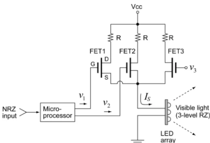
2.1 Visible light communication (VLC) transmitter In the VLC transmitter, three-level RZ modulation is used for flicker-free transmission. Fig. 1 schematically shows the configuration of the VLC transmitter.
The VLC transmitter is composed of a microprocessor, three FETs, and an LED array. The input signals to the VLC transmitter are codes based on the American Standard Code for Information Interchange (ASCII) in NRZ waveforms. When the input signal is applied to the input port, the microprocessor outputs two voltages
(v
1and v
2), which are applied to the gates of FET1 and FET2, respectively. The source currents of FET1 and FET2 are proportional to their gate voltages v
1and v
2, respectively. The two source currents are added at the common source point and the total current (I
S) flows to the LED array. The output light of the LED array is proportional to the sum of the two source currents and its intensity constitutes a three-level RZ waveform. FET3 is not directly concerned with the RZ modulation; it is used for illumination control by changing the DC gate voltage v
3.
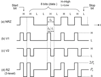
The three-level RZ waveform generation process is explained in Fig. 2. Fig. 2(a) is an arbitrary ASCII code character in NRZ waveform. For convenience, we used an 8-bit character “V” with a start bit and a stop bit. This format is generally used in universal asynchronous receiver and transmitter (UART) communication between computers or microprocessors. The microprocessor in the transmitter generates v
1and v
2signals corresponding to the NRZ input character, as shown in Figs. 2(b) and 2(c), respectively.
When the NRZ input bit is in “high (H)” state, v
1is in “H” state only during the former half part of the bit time (t
B) and in “low (L)” state elsewhere, as shown in Fig. 2(b). When the NRZ input bit is in “H” state, v
2is in “L” state only during the latter half part of the bit time, and in “H” state elsewhere, as shown in Fig. 2 (c).
The sum of the two source currents of FET1 and FET2 is proportional to the sum of the two voltages v
1and v
2; thus, the LED light constitutes a three-level RZ waveform as shown in Fig.
2(d). The optical power densities at the lowest, medium, and highest levels are designated as 0, P
0, 2P
0, respectively, in Fig.
2(d).
When the input NRZ bit is in “H” state, the average optical power in the three-level RZ modulated light can be calculated as follows.
Fig. 1. Configuration of the visible light communication (VLC)
transmitter.
(1)
Here, t
Bis a one-bit time of the NRZ input, t
H= 0.5t
B, which is the duration of the highest level in the three-level RZ modulated light, and P
0is the optical power density at the medium level.
When the input NRZ bit is in “L” state, the average optical power in the three-level RZ modulated light is constant at the medium level P
0, as shown in Fig. 2(d), that is
(2) Thus, the average optical power is constant at the medium level P
0independent of the bit state. Consequently, the average optical power of the three-level RZ modulated light achieves constant illumination without LED flicker.
To observe the conversion process from NRZ input to three- level RZ waveform in the VLC transmitter, a character “V” was transmitted repeatedly; we observed the corresponding signal waveforms in the transmitter. Fig. 3 shows the voltage waveforms that were observed with an oscilloscope.
Fig. 3(a) is the voltage waveform of a character “V” in 9.6 kbps UART format. The ASCII code of character “V” is “01010110.”
When the least significant bit is sent first, the bit sequence from left to right becomes “01101010.” Further, a start bit “0” and a stop bit “1” are added before and after the character, respectively.
Thus, the waveform of the character “V” becomes a 10-bit signal, i.e., “0011010101.”
In the UART transmission using Recommended Standard 232
(RS-232), “H” is assigned to a “0” bit and “L” to a “1” bit.
Consequently, the NRZ waveform of the character “V” becomes
“HHLLHLHLHL,” as shown in Fig. 3(a). Figs. 3(b) and 3(c) correspond to the voltages v
1and v
2, which were applied to the gates of FET1 and FET2, respectively. Fig. 3(d) indicates the voltage at the common source point where the two FET source currents were added. The total current flowed into the LED array and three-level RZ visible light was radiated into the free space.
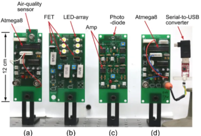
In the VLC transmitter, we used an ATmega8 microprocessor, three IRF540 FETs, and an LED array, which was fabricated in the form of a 2 × 3 planar array using six 1 W white-light LEDs.
2.2 VLC receiver
The VLC receiver detects the visible light and recovers the data sent from the VLC transmitter. The schematic diagram of the VLC receiver is shown in Fig. 4.
The VLC receiver is composed of a PD, amplifiers, an RC-HPF, and a microprocessor. The PD converts the input light to photocurrent, which flows through the load resistance R
L. The PD voltage across R
Lis amplified and passed through the RC-HPF.
( )
(
0)
00 0
5 . 0 1 2
1 2 ) 1 (
) (
P t t P
t t P dt t t P H P
B B
H B
t B t avg
B
=
×
=
×
=
= ∫=
)
0( L P P
avg=
Fig. 2. Three-level return-to-zero (RZ) signal generation: (a) non-RZ (NRZ) input, (b) voltage v
1, (c) voltage v
2, and (d) three-level RZ output.
Fig. 3. Waveforms observed in VLC transmitter: (a) input NRZ waveform, (b) voltage v
1, (c) voltage v
2, and (d) three-level RZ waveform.
Fig. 4. Configuration of the VLC receiver.
The RC-HPF cuts off the 120 Hz noise and outputs spike signals at the rising and falling edges of the three-level RZ signal. The microprocessor regenerates the NRZ data using the spikes from the RC-HPF output. The data recovery process in the VLC receiver is illustrated in Fig. 5.
In environments where the 120 Hz optical noise from adjacent lighting lamps is incident on the PD, the three-level RZ signal is mixed with optical noise and the PD voltage is as illustrated in Fig. 5(a). When the PD voltage passes through the RC-HPF, the 120 Hz noise disappears, and voltage spikes appear at the RC- HPF output, as shown in Fig. 5(b). The positive spikes appear at the rising edges and the negative spikes at the falling edges of the three-level RZ signal. When the NRZ bit in the transmitter is in
“H” state, two positive spikes and one negative spike appear in a one-bit time (t
B). When the NRZ bit in the transmitter is in “L”
state, no spike appears. Thus, we can use the negative spikes for regenerating the NRZ data sent from the transmitter.
Fig. 5(c) illustrates the inverted negative spikes that appear at the diode output after the inverted amplifier. These inverted negative spikes are applied to the interrupt port of a microprocessor. For each negative spike, the microprocessor generates a NRZ “H” bit whose duration corresponds to the one- bit time (t
B) of the NRZ data. Thus, the NRZ data is regenerated in the receiver, as shown in Fig. 5(d). The NRZ waveform regenerated in the receiver has the same shape as that in the transmitter; further, a time delay of half a bit time (t
B/2) exists between the transmitter and the receiver.
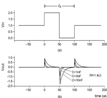
To verify the operation of the RC-HPF in the VLC receiver, we simulated its response to the three-level RZ signal and the 120 Hz noise using the PSpice program. The three-level RZ voltage at the
input of the RC-HPF for one “H” bit of the NRZ data can be expressed as follows.
(3) Here, Vs is voltage amplitude, U(t) is the step function, and t
Bis the one-bit time of the NRZ data in the VLC transmitter. Fig.
6 shows the simulated voltage of the RC-HPF. In the simulation, we used unit amplitude, that is V
S= 1; the bit time t
B= 100 µs;
the resistance of the RC-HPF was set to R = 1 kΩ; moreover, the capacitor C was used as a parameter. Fig. 6 shows the simulation result.
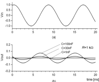
Figs. 6(a) and 6(b) are the three-level RZ input and output voltage waveforms of the RC-HPF, respectively. Positive and negative spikes appear at the rising and falling edges of the three- level RZ voltage, respectively. The negative spike appears once only at each “H” bit of NRZ data and it is used for recovering the NRZ bit sequence sent from the transmitter. The RC-HPF response to the 120 Hz noise was also simulated using the PSpice program. The 120 Hz noise can be expressed approximately as presented below.
(4) Here, V
Nis the noise voltage amplitude. In the simulation, we used unit amplitude, that is V
N= 1; moreover, the resistance of the RC-HPF was set to R = 1 kΩ, and the capacitor C was used as the parameter. Fig. 7 shows the simulation result.
Figs. 7(a) and 7(b) are the 120 Hz noise input and output voltage waveforms of the RC-HPF, respectively. As seen in Fig. 7
[ ( ) 2 ( 0 . 5 ) ( ) ]
)
(
S B BRZ