a) Department of Electrical Engineering and Computer Science, Graduate School of Engineering, Nagoya university, Japan.
b) Graduate School of Science and Engineering, Tokyo Institute of Technology, Japan.
c) Toyota Central R & D Labs., Inc.
※This work is done in Nagoya university, Japan, collaborating with Toyota Central R & D Labs., Inc., Japan.
‡corresponding author : H. Chinthaka N. Premachandra ([email protected])
․Receipt date (July 13,2009), Amendment date (July 29,2009), Publication definite date (July 29,2009)
Edge-Based Tracking of an LED Traffic Light for a Road-to-Vehicle Visible Light Communication System
H. Chinthaka N. Premachandraa)‡, Tomohiro Yendoa), Mehrdad Panahpour Tehrania), Takaya Yamazatoa), Toshiaki Fujiib), Masayuki Tanimotoa), and Yoshikatsu Kimurac)
Abstract
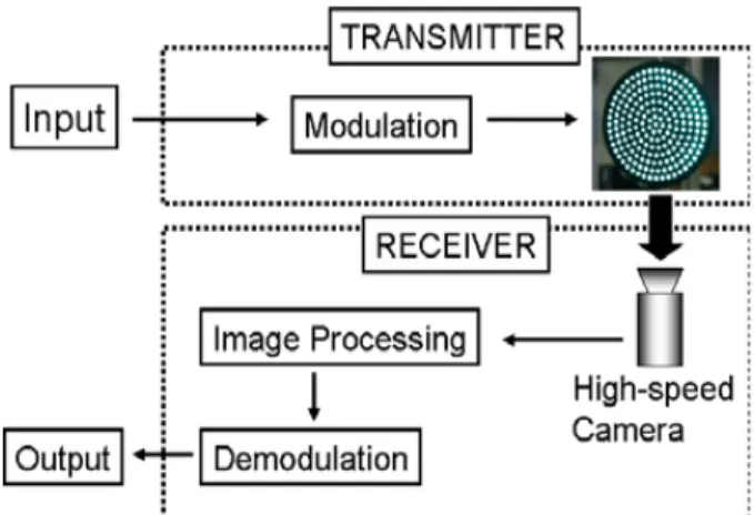
We propose a visible light road-to-vehicle communication system at intersection as one of ITS technique. In this system, the communication between vehicle and a LED traffic light is approached using LED traffic light as a transmitter, and on-vehicle high-speed camera as a receiver. The LEDs in the transmitter are emitted in 500Hz and those emitting LEDs are captured by a high-speed camera for making communication. Here, the luminance value of each LED in the transmitter should be found for consecutive frames to achieve effective communication. For this purpose, first the transmitter should be identified, then it should be tracked for consecutive frames while the vehicle is moving, by processing the images from the high-speed camera. In our previous work, the transmitter was identified by getting the subtraction of two consecutive frames. In this paper, we mainly introduce an algorithm to track the identified transmitter in consecutive frames. Experimental results using appropriate images showed the effectiveness of the proposal.
Keyword : Visible light communication, High-speed camera, LED traffic light, Edge detection
I. INTRODUCTION
DEVELOPMENT of traffic vehicles serves great support for humans in different ways. The number of the motor ve- hicles in the world increases every year. According to this, the number of traffic problems such as environment pollu- tion, traffic jams, and traffic accidents have also increased.
In last few decades, lots of researches have been conducted
to give solutions for these traffic problems. Specifically, the electrical motor vehicles and hybrid vehicles which ex- haust less Carbon dioxide, were already introduced to con- trol the environment problem. On the other hand, Intelli- gent Transport System (ITS) has been introduced to de- crease traffic jam and traffic accidents with the develop- ment of information technology. The advancing areas of ITS technology can be divided into two main groups, as automatic driving systems and driver assistant systems. The computers make all the decisions in automatic driving sys- tems while they assist the driver for making decisions in driver assistant systems, by providing the external and in- ternal information of the vehicle. In both systems, image processing is one of the key technologies for detecting information. In many of these systems, cameras capture the images of external or internal environment of the vehicle 특집논문-09-14-4-09
and necessary information is extracted by image pro- cessing. The cameras are installed according to desired cap- turing area, either external environment or on the vehicle.
In many driver assistant systems, on-vehicle cameras are used to capture images of external environment. Some studies have been conducted for detecting obstacles, traffic signs, and signal lights and so on[1][2][3][4][5][6]. In this study, we propose road-to-vehicle visible light communica- tion system using on-vehicle high-speed camera as a re- ceiver and LED traffic light as a transmitter. Here, the LEDs in the transmitter emit light in 500Hz and the im- ages, which include those emitting LEDs are captured by a high-speed on-vehicle camera in 1000fps, while the ve- hicle is moving. These images are processed to gain the luminance value of each LED for conducting commu- nication. For this purpose, first the transmitter should be identified, then it should be tracked for each consecutive frame, and the luminance value of each LED in the trans- mitter should be captured to achieve effective commu- nication. Here, we applied the method used by Iwasaki et al. [3] for identifying the transmitter. In their method, the transmitter is identified getting the subtraction of two con- secutive frames. In this paper, we mainly introduce a new edge-based method to track the identified transmitter in consecutive frames for certain moving distance of the vehicle. In this paper, we approached to track the trans- mitter almost starting 70m away from transmitter and stop at almost 20m away from transmitter. The experiments were conducted to confirm the effectiveness of the proposal under different conditions. According to experiments, the proposal was very effective in tracking the identified trans- mitter for certain moving distance of the vehicle.
This paper consists of five main sections to explain our project work. The section Ⅱ makes a brief explanation about visible light communication and section Ⅲ and Ⅳ introduce the proposals for identifying and tracking the LED traffic light for proposed system. The experimental
results and discussion are described in section Ⅴ. The sec- tion Ⅵ concludes the paper.
Ⅱ. Visible Light Communication
Visible light communication is one of wireless communi- cation methods using light sources. It is able to transfer da- ta by emitting light source, and able to receive them by light sensor. There are several advantages in this communi- cation method. One is that visible light is not harmful to human body. And it is able to transmit with high power.
Other common wireless communication methods, such as radio waves and infra-red light are concerned to be danger- ous to human body. Compared to radio waves and infra-red light, it has more advantages: there are no legal limitation for any existing light source, such as room illuminations and displays to be used. It can be used at the places where radio waves cannot be used, for example hospitals and areas around precision machines.
Fig. 1. Proposed visible light communication
Komine and Nakagawa[7] have achieved visible light communication using illumination light. It is a communica- tion between PCs and illumination light, and considered as an alternative method for the wireless LAN. As latest ap-
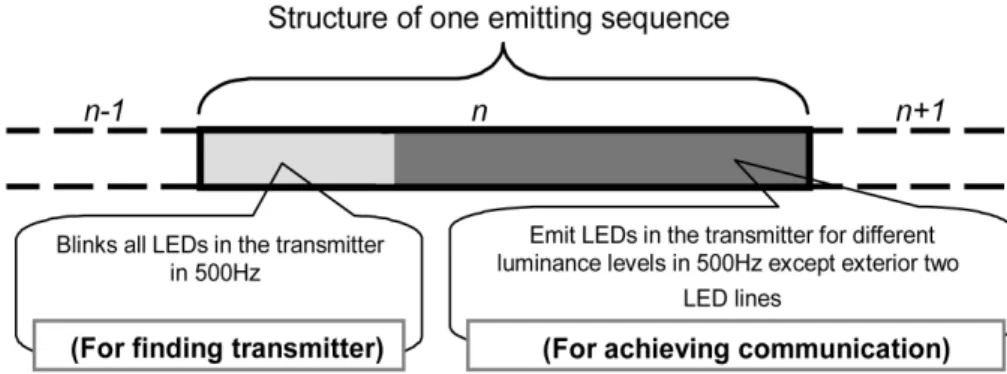
Fig. 3. Emission patterns of one sequence
plication of visible light communication (VLC), Suzuki et al. [8] introduced a support system for visually impaired person by utilizing visible light communication technology at signalized intersections. In that system, when a pedes- trian receives visible light from a pedestrian traffic signal via a portable receiver, pedestrian can listen to sound in- formation on earphone or headphones. Here, the correct moving direction for visually impaired person is guided by changing the hearing sound.
At present, light bulbs and fluorescent lights are the light source for dominant room illumination. LEDs, however, are also getting popular as dominant light source. Recently, LEDs are used in traffic signal light and many light decorations. LEDs have features like longer operating life, lower power consumption, and smaller size. The emitting efficiency is also comparatively higher than the fluorescent light and thus it will surely replace the bulbs and fluo- rescents in the near future. There are many light emitters surrounding us and any of them could become a transmitter of this communication. For examples, PC display, TV, electric bulletin board, and cellular phone display so on.
Figure 1 shows the structure of the proposed visible light communication system using LED traffic light as a trans- mitter and high-speed camera as a receiver. Here, the traf- fic light includes 256 LEDs. If these LEDs could be recog- nized individually, it is possible to use each of them as a separate transmitter communicating in parallel at the same
Fig. 2. Parallel communication
time. This is the main advantage of using a camera as a receiver. Light source using LED usually contain a number of LEDs. In the proposed system, we approach to recognize each LED of the traffic light (transmitter) by image processing. Thus, if we consider one transmitter with many LEDs as a set of small transmitters, we can dramatically increase the communication speed by modulating each LED individually (Fig. 2). In other words, each LED trans- mits different data in parallel and they are received at the same time. Moreover, we can communicate with several transmitters and receive different information in parallel.
However, using a camera as the receiver has some dis- advantages. The camera should have high frame rate to achieve good communication speed. For this purpose, im- age processing in the receiver should be in real time and it might be harder on a computer when a high-speed cam- era is used. We plan to achieve this using hardware.
Another issue is the modulation method. Since this is a unique communication method using visible light and im- age, it requires particular modulation method which consid-
ers the characteristics of the communication. We use hier- archical coding[10] for visible light communication, which modulates data on spatial frequency and enables long dis- tance communication.
In the proposed system, the high-speed camera (Receiv- er) is installed on the vehicle. The transmitter (LED traffic light) is fixed on the road. In this paper, the LED traffic light which is used for experiment is specially prepared to be able to emit LEDs in 500Hz using a PC. It is not a normal traffic light. We developped image sensor to identi- fy the LED traffic light and track it for consecutive frames by processing the images from high-speed camera, for cer- tain moving distance of the vehicle. In the next two sec- tions, the methods for identifying and tracking the trans- mitter using image processing are explained in details respectively.
Ⅲ. Identification of the Transmitter
1. Emission Patterns of Transmitter
The transmitter used for the experiments is square in shape and it consists of 256(16x16) LEDs. Communication is achieved by emitting them. They are emitted sequence by sequence and in the first half of the sequence, all LEDs are emitted (ON and OFF) at the same time in 500Hz (Fig.
3). This stage is set for identifying the transmitter by image sensor at receiver using image processing. The proposal for identifying transmitter is explained in the next section. In the second half of the sequence, LEDs in the transmitter are emitted with four different levels in 500Hz, except LEDs in the two exterior lines, and communication is con- ducted in this stage(Fig. 3). In this paper, these non-emit- ting two exterior lines are kept to make it easy to track the transmitter by image processing. The proposal for tracking the transmitter is detailed in section Ⅳ.
2. Method for Identifying Transmitter
As mentioned in above section, the transmitter is emitted (ON and OFF) in 500Hz in the first half of the sequence.
Fig. 4. An arbitrary frame including the transmitter in the center
Fig. 5. The result of transmitter identifying for the arbitrary frame shown in Fig. 4
This stage is set to identify the transmitter by receiver with image processing. Here, while the vehicle is moving, the
Appointed Frame
Edge Detection
Selection of Transmitter Area Candidates (Cno)
Extraction of Transmitter Area [ETA]
Dilation of Selected Edge
Image Area Cno=0
[STAC]
[ETA]
No
Yes
Extracted Transmitter
(Next Frame)
Cno>0 Cno=0
Cno>0
No [STAC]
Yes
End
(Next Frame)
End
(Next Frame)
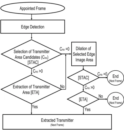
Fig. 6. Flow of proposed transmitter detection method
receiver (High-speed camera) installed in the vehicle takes images of the road with 1000fps. If transmitter exists on the road and it is at the first half of the sequence, it is ex- pected to appear on images once in two frames, since traf- fic light emits (ON and OFF) for 500Hz and high-speed camera takes images in1000fps. In this paper we applied the method used by Iwasaki et al. [3] for identifying the transmitter. In this method, first, two consecutive frames are subtracted. The result image include approximate trans- mitter with some noise, if it being in first half of the sequence. This result image is processed for binarization and noise reduction to get almost exact transmitter area.
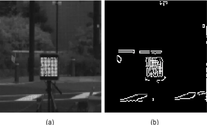
Figure 4 shows arbitrary frame with transmitter, and Fig.
5 shows the identified transmitter using this method. After identifying the transmitter, area of 125x125pixels including transmitter is cut out (Fig. 7(a)). Then the transmitter is de- tected in consecutive frames by processing the correspond-
ing cut out area only. If the transmitter stays out of this area, the processing restarts from finding step. Next section explains the proposal for transmitter tracking in details.
Ⅳ. Procedure for Achieving Consecutive Tracking of Identified Transmitter
After the transmitter has been identified, it is necessary to track it in consecutive frames for making efficient communication. Iwasaki et al. [3] used template matching for same kind of detection. But, template matching is high- ly time and memory consuming. In the case of tracking a stable object using a moving camera (on-vehicle high- speed camera), the matching images should be updated to achieve good tracking. In this paper, we approach to detect the identified transmitter introducing an edge based me-
thod. Edge information is one of the key point in object detection. Charmichael et al. [9] used edge information in shape-based recognition of wiry objects. In our proposal, we use canny edge detector for detecting edges[11]. In this proposal, transmitter area is tracked in consecutive frames while the vehicle is moving for certain distance, after iden- tifying it. Figure 6 shows the flow of tracking and each main steps are detailed in next sub sections.
1. Edge Detection
Canny edge detector is used for edge detection, since it has the ability to connect edges having different gradient values. And Canny edge detector can give exact edge points, since it decides edge points searching the direction of the edge points. In the canny edge detector, Gaussian filter smoothes the image, then the gradient and its direc- tion for each pixel are calculated using Sobel filter.
Non-maximum suppression processing is conducted quan- tizing gradient direction, and finally edge points are gained using hysteresis threshold method. There are Two thresh- olds( Cthres1 and Cthres2, (Cthres1>Cthres2)) are applied (hysteres is threshold) to gradient to gain appropriate edge points. Here, the pixels having gradient value greater than Cthres1 are selected as edge points and the pixels having gradient value less than Cthres2 are not selected as edge points. In the case of the gradient value between Cthres1 and Cthres2: If these pixels are connected to edge points meaning that, they connect to pixels having (gradient>
Cthres1) through the pixels having(Cthres1 > gradient >
Cthres2)they are also selected as edge points. The edge points having different gradient values can be connected to have the clear edge components by varying these two thresholds. In this paper, we determined these two thresh- olds experimentally as Cthres1=250 and Cthres2=180. An example of one frame is shownin Fig. 7(a) and its edge detection results are shownin Fig. 7(b). The transmitter area
candidates are selected using theses edge components in the edge image as explained in next section.
(a) (b)
Fig. 7. Edge detection, (a) Arbitrarily frame, (b) Edge image
2. Selection of Transmitter Area Candidates
In this proposal, transmitter area candidates are selected regarding the circumscribing rectangle of edge component.
First, circumscribing rectangles of each edge component are calculated. Then the transmitter area candidates (Cno) are selected by the following conditions.
pre now pre
H −offset H< <H +offset
pre now pre
W −offset W< <W +offset
|Hnow−Wnow| 2≤ pixels
Here, W and pre H mean the width and height of the pre just previously detected transmitter, and WnowandHnow
mean width and height of searching circumscribing rectangle. According to these conditions, if a circum- scribing rectangle of the edge component is almost same in size as just previously detected transmitter, that rectangle is selected as transmitter area candidate. Here, the trans- mitter which is used for experiments is square in shape.
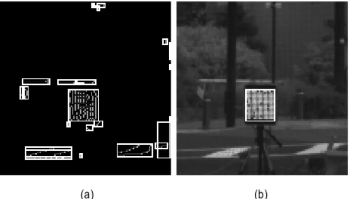
Thus, the circumscribing rectangle of edge component cor- responding to the transmitter should almost be square in shape. The gained circumscribing rectangles for Fig. 7(b) image are shown in Fig. 8(a). The transmitter candidate se- lection results are shown in Fig. 8(b). There is only one candidate for this image. The is set for 2 pixels in the experiments. Figure 9(a) and (b) are some examples for appearing multiple candidates. It might be possible to have a few candidates depending on the environment, where transmitter is installed. For this reason, we conduct trans- mitter extraction from candidates and the extraction method is detailed in next section.
(a) (b)
Fig. 8. Calculation of circumscribing rectangle and selection of trans- mitter area candidates, (a) Circumscribing rectangles, (b)Transmitter area candidates
(a) (b)
Fig. 9. Appearing of multi transmitter candidates, (a) Overlapped candi- dates, (b) Individual candidates
3. Extraction of Transmitter Area from Candidates
As mentioned above, in some cases it is possible that a few transmitter candidates ( ) appear at the trans- mitter candidate selection stage. Even if a single candidate is appeared, it is necessary to confirm whether that candi- date is a real transmitter or not. In the case of a single can- didate, the confirmation is conducted comparing the length
and middle point position (Mnow x_ ,Mnow y_ ) of the present candidate with same data in just previous detections.
The transmitter likelihood conditions are defined using side length and middle point as below, considering just pre- vious detections.
■ The side length difference of the transmitter between three consecutive frames does not decrease more than 1 pixel, and it does not increase more than 2 pixels in three consecutive frames.
■ The middle point movement of the transmitter does not exceed 5 pixels in three consecutive frames.
In the case of one candidate, if the candidate fulfills the above conditions, that candidate is selected as transmitter.
The candidate which is under above conditions is extracted if multiple candidates are appeared. In some cases, few candidates out of the candidates fulfill the above con- ditions, it was complicated to extract real transmitter. In these cases, likelihood probability of the transmitter is de- fined as arg max ( , )P L M to extract the real transmitter.
( , )
P L M is defined as Equation (1), P L( ) and P M( )mean likelihood probability of the transmitter regarding the side length and middle point respectively.
( , ) ( ) ( )
P L M =P L +P M (1)
Original frame Edge detection Dilation process Extracted transmitter Fig. 11. Flow of transmitter detection by dilating an appointed edge image area
( ) ( diff) P L =P L
1
( (1 ), )
i
diff diff
n
L L t n t n
=
=∑ − − − (2)
( ) ( diff) P M =P M
1
( (1 ), )
i
diff diff
n
M M t n t n
=
=∑ − − − (3)
In Equation (2) and (3), means the side length dif- ference of the consecutive detected transmitters, and
means the middle point difference of the consecutive pre- viously detected transmitters. is time sequence and is the number of previous detections used for comparison. In this paper, comparison is conducted considering three ( ) previous detections. The variation of the and are defined as Equation (4), (5), and (6). The values for and are set to 0.1 and 0.05 respectively, in the experiment.
( diff) L diff 1 (0 diff 2)
P L = −m ∗L + ≤L ≤ (4)
( diff) L diff 1 ( 1 diff 0)
P L =m ∗L + − ≤L ≤ (5)
( diff) M diff 1 (0 diff 5)
P M = −m ∗M + ≤M ≤ (6)
The candidate having maximum value for is se- lected as transmitter.
4. Dilation of Appointed Edge Image Area
In some cases, it is not possible to get the transmitter
area as a candidate in selection of transmitter candidates step, because the corresponding edges for the transmitter did not appear as one component, but they appeared as several components.
t-1 t
l pixels
M M
Detected transmitter in previous frame
Dilation area
(l-offset)pixels
Fig. 10. Selection of dilation area
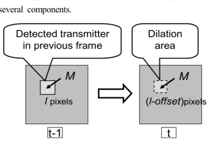
This happened when images of the transmitter got blur- red in certain situations. But, according to the experiments so far, these kinds of cases are comparatively less. To solve this problem, if the candidates or extracted trans- mitter did not appear in candidate selection step [STAC]
or Transmitter extraction step [ETA], the appointed edge image area is dilated. This dilating edge image area is selected considering the corresponding area of just pre- viously detected transmitter as indicated in Fig. 10. The rectangular area, having height and width as (
) and ( ), respectively and middle point as (Mpre x_ ,Mpre y_ )in the edge image is selected to be dilated. Here, the offset is set for 1 pixel. After the dilation, candidate selection step [STAC] and transmitter extraction
step [ETA] are applied to the edge image again. If the transmitter is not extracted after dilation, the process moves to the next frame as shown in processing flow (Fig. 6). An example of transmitter tracking by dilating an appointed edge image area is shown in Fig. 11. Here, the original image is processed for edge detection. In this case, the cir- cumscribing rectangle belonging to the transmitter did not appear, because exterior edge component was split in to several components. The split edge components could be connected by dilation process and transmitter could be found by calculating the circumscribing rectangle of dilated edge component.
Ⅴ. Experimental Results and Discussion
1. Experimental Results
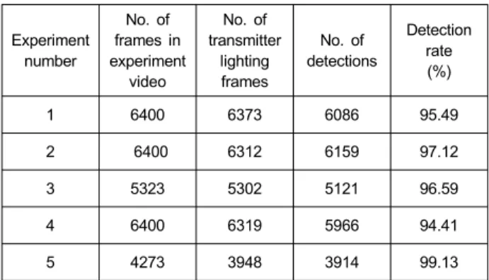
The experiments were conducted to confirm the effec- tiveness of proposed transmitter tracking method. We fixed a high-speed camera on a vehicle and images were cap- tured while driving the vehicle in more than 30km/h, to- wards the transmitter. Transmitter is emitted in 500Hz and images of emitting transmitter were captured by a high-speed grayscale camera which is fixed on the moving vehicle in 1000fps. The moved distance of the vehicle is from 70m to 15m, from the transmitter. In the identifying stage, transmitter could be identified effectively. The re- sults of tracking, after identifying the transmitter are main- ly explained in this paper. Figure 12(a)~(l) show some de- tection results of one experiment when the vehicle is away from different distance from the transmitter. Table 1 sum- marizes results of five experiments conducted under differ- ent conditions. Experiment 1, 2, and 5 in Table 1 were con- ducted under the cloudy(dark) weather condition and Exp.
3 and 4 were conducted under the sunny weather condition.
The detection rate is defined to evaluate the proposal, as
Experiment number
No. of frames in experiment
video
No. of transmitter
lighting frames
No. of detections
Detection rate (%)
1 6400 6373 6086 95.49
2 6400 6312 6159 97.12
3 5323 5302 5121 96.59
4 6400 6319 5966 94.41
5 4273 3948 3914 99.13
Table 1. Summary of several experimental results
below Equation (7). In all experiments, there was not any error detection.
Numberof detections 100 Detection rate
Numberof transmitterlighting frames
= × (7)
According to total experimental results, the average de- tection rate with the proposal introduced in this paper was 96.55%, and the detection rate with template matching as conventional method[3] was 61.2%. These results showed that the proposal is very effective in tracking the desired transmitter (Traffic light) in consecutive frames compared to the conventional method.
2. Discussion
In this paper, a new traffic light (transmitter) tracking method was introduced for a road-to-vehicle visible light communication system with a traffic light as a transmitter and a high-speed on-vehicle camera as a receiver. This new method mainly tracks an emitting traffic light detecting the edges of traffic light image and calculating circumscribing rectangle of the edge component. Here, the canny edge de- tector was used for edge detection, and the necessary thres- holds for this detector were decided experimentally. We observed that, this detector can create appropriate edges of
(a) Approximately 70m far from transmitter
(b) Approximately 65m far from transmitter
(c) Approximately 60m far from transmitter
(d) Approximately 55m far from transmitter
(e) Approximately 50m far from transmitter
(f) Approximately 45m far from transmitter
(g) Approximately 40m far from transmitter
(h) Approximately 35m far from transmitter
(i) Approximately 30m far from transmitter
(j) Approximately 25m far from transmitter
(k) Approximately 20m far from transmitter
(l) Approximately 15m far from transmitter Fig. 12. Examples of transmitter detection while vehicle being moved between 70m to 15m
transmitter using thresholds. In the transmitter candidate se- lection, the multiple candidates almost appeared when the vehicle is far from the transmitter, and the number of candidates got less when vehicle reached near the transmitter. The transmitter could be extracted from candi- dates mainly on the defined transmitter likelihood conditions. But, in the cases when the few candidates are almost similar, the transmitter could be extracted using the defined transmitter likelihood probability.
This extraction didn’t make any error tracking. The dila- tion of appointed edge image area was able to connect the
disconnected edge components belonging to the transmitter in edge detection step. As a result, some miss-tracking of the transmitter could be minimized. The experiments were conducted to confirm the effectiveness of the proposed transmitter tracking method under different conditions. The results of tracking transmitter in the dark environment is a little better than the results under sunny conditions.
According to the overall experimental results, proposed method was very effective in tracking the desired trans- mitter.
Ⅵ. Conclusion
In this paper, a new traffic light tracking method was introduced for a road-to-vehicle visible light communica- tion system with a traffic light as a transmitter and a high-speed on-vehicle camera as a receiver. This proposal is mainly tract the traffic light by calculating the circum- scribing rectangles of edge components which are related to traffic light. The experiments using appropriate images were conducted to confirm the effectiveness of the proposal. The results showed that the proposal was very effective for desired tracking.
References
[1] F. Lindner, U. Kressel, and S. Kaelberer, “Robust Recognition of Traffic Signals,” in Proc. IEEE Intelligent Vehicle Symposium, Parma, 2004, pp. 49-53
[2] K. Mori, T. Takahashi, I. Ide, H. Murase, T. Miyahara, and Y.
Tamatsu. “Recognition of foggy conditions by in-vehivle camera and millimeter waveradar,” Proc. IEEE Intelligent Vehicle Sympos- ium, Istanbul, 2007, pp. 87-92
[3] S. Iwasaki, C. Premachandra, T. Endo, T. Fujii, M. Tanimoto, Y.
Kimura, “Visible Light Raod-to-Vehicle Communication Using
High-Speed Camera,” Proc. IEEE Intelligent Vehicle Symposium, Eindhoven, 2008, pp. 13-18
[4] G. Song, K. Lee, and J. W. Lee, “Vehicle Detection by Edge-Based Candidate Generation and Appearance-Based Classification,” Proc.
of IEEE Intelligent Vehicle Symposium, Eindhoven, 2008, pp.
446-451
[5] P. Jeong and S. Nadevshi, “Obstacle Detection Based on the Hybrid Road Plane under the Weak Calibration Conditions,” Proc. of IEEE Intelligent Vehicle Symposium, Eindhoven, 2008, pp. 428-433 [6] C.G. keller, C. Sprunk, C. Bahlmann, G. Baratoff, and J. Giebel,
“Real-Time Recognition of U.S. Speed Signs,” Proc. of IEEE Intelligent Vehicle Symposium, Eindhoven, 2008, pp. 518-523 [7] T. Komine and M. Nakagawa, “Fundement analysis for visible-light
communication system using LED lights,” IEEE Trans. of Consu- mer Electronics, Vol. 50, Issue 1, pp. 100-107, Feb. 2004 [8] K. Suzuki, M. Fujita, Y. Hayashi, and K. Fukuzono, “A Study on
Visually Impaired Person’s Support System Utilizing Visible Light Communication Technology at Signalized Intersections,” Interna- tional Journal of ITS Research, Vol. 5, No. 1, pp.37-45, Oct. 2007 [9] O. Carmichael and M. Hebert, “Shape-Based Recognition of Wiry
Objects,” IEEE Transaction of Pattern Analysis and Machine Intelligence, Vol. 26, No. 12, pp. 1537-1552, Dec. 2004
[10] S. Arai, S. Mase, T. Yamazato, T. Endo, T. Fujii, M. Tanimoto, K.
Kidono, Y. Kimura and Y. Ninomiya, “Experiment on Hierarchical Transmission Scheme for Visible Light Communication using LED Traffic Light and High-Speed Camera,” in Proc. IEEE International Symposiumon Wireless Vehicular Communications (WiVeC’07), 2007, pp. 2174-2178
[11] John Canny, A Computational Approach to Edge Detection, IEEE Transactionon Pattern Analysis and Machine Intelligence, Vol. 8, Issue 6, pp. 679-698, Nov. 1986
저 자 소 개
H.Chinthaka N. Premachandra
H. Chinthaka N. Premachandra received the B.Eng. and M. Eng. degrees from Mie University, Japan in 2006 and 2008 respectively. He is currently a Ph.D candidate with Department of Electrical Engineering and Computer Science, Graduate School of Engineering, Nagoya university, Japan. His current research interests include image and video processing applications for Intelligent Transport System(ITS) and document image processing. He is a member of the Institute of Electronics, Information and Communication Engineers (IEICE), Japan and Japan Society for Fuzzy Theory and Intelligent Informatics (SOFT).
저 자 소 개
Tomohiro Yendo
Tomohiro Yendo received the B. Eng. and M. Eng. and Ph.D. degrees from Tokyo Institute of Technology, Tokyo, Japan, in 1996, 1998, and 2001, respectively. From 1998 to 2002, he was a researcher for the Advanced 3-D Tele- Vision Project at the Telecommunications Advancement Organization(TAO) of Japan. From 2002 to 2004, he was a research fellow at Japan Science and Technology Agency(JST).
He is now an assistant professor at Nagoya University, Nagoya, Japan. His current research interests include 3-D image display, capturing and processing.
Mehrdad Panahpour Tehrani
Mehrdad Panahpour Tehrani received Dr.Eng. degree in Information Electronics from Nagoya University, Nagoya, Japan in 2004. From 2004 to 2007 he was with Information Technology Center, Nagoya University as a Post-Doctoral Researcher. He worked as an Associate Research Engineer with Ultra Realistic Communications Laboratory, KDDI R&D Laboratories Inc., Saitama, Japan, from 2007 to 2009. Currently, he is working as an Associate Professor at the Department of Electrical Engineering, Graduate School of Engineering, Nagoya University, Japan.
His research interests are 3D image processing and communication, multiview coding, distributed source coding in camera sensor networks, and 3D media integration and communication.
Takaya Yamazato
Takaya Yamazato received the Ph.D. degree from Keio University, Yokohama, Japan, in 1993. From 1993 to 1998, he was an Assistant Professor in the Department of Information Electronics, Nagoya University, Japan. From 1997 to 1998, he was a visiting researcher of the Research Group for RF Communications, Department of Electrical Engineering and Information Technology, University of Kaiserslautern. Form 1998 to 2004, he was an Associate Professor in the Center for Information Media Studies, Nagoya University, Japan. Since 2004, he has been with the EcoTopia Science Institute, Nagoya University, Japan. His research interests include sensor networks, satellite and mobile communication systems, CDMA, and visible light communications. Dr.Yamazato received the IEICE Young Engineer Award in 1995 and the IEEE Communication Society 2006 The Best Tutorial Paper Award in 2006. He is a member of IEEE and SITA.
Toshiaki Fujii
Toshiaki Fujii received the Dr.E. degree in Electrical Engineering from the University of Tokyo in 1995. From 1995 to 2007, he was with the Graduate School of Engineering, Nagoya University. He is currently an Associate Professor in the Graduate School of Science and Engineering, Tokyo Institute of Technology. His current research interests include multi-dimensional signal processing, large-scale multi-camera systems, multi-view video coding and transmission, free-viewpoint television, and their applications for Intelligent Transport Systems. He is a member of the IEEE, The Institute of Electronics, Information and Communication Engineers, and the Institute of Image Information and Television Engineers of Japan.
저 자 소 개
Masayuki Tanimoto
Masayuki Tanimoto (M’71-SM’07) received the B.E., M.E., and Dr.E. degrees in electronic engineering from the University of Tokyo, Tokyo, Japan, in 1970, 1972, and 1976, respectively. He joined Nagoya University, Nagoya, Japan, in 1976 and started research on visual communication and communication systems. Since 1991, he has been a Professor at Graduate School of Engineering, Nagoya University. His current research interests include image coding, image processing, 3-D images, FTV and ITS.
Dr. Tanimoto is the President of ITE. He was the Chairperson of Technical Group on Communication Systems of IEICE, the Chairperson of the Steering Committee of Picture Coding Symposium of Japan, IEICE Councilor, ITE Councilor and Tokai Section Chair of IEICE. He is a member of the International Steering Committee of the Picture Coding Symposium. He received the Ichimura Award, the TELECOM System Technology Award from The Telecommunications Advancement Foundation, the Niwa-Takayanagi Paper Award from ITE, IEICE Fellow Award, IEICE Achievement Award, ITE Fellow Award, and the Commendation for Science and Technology by the Minister of Education, Culture, Sports, Science, and Technology.
Yoshikatsu Kimura
Yoshikatu Kimura is a senior researcher with Toyota Central R & D Labs., Inc., Japan.