I.INTRODUCTION
One of the fastest growing applications of satellite systems is the satellite based Global Navigation Satellite system. Out of the current navigation system, GPS is the only one with fully operational status and 99% service coverage over the world.
The other system partially existing is GLONASS, which is Russian system and currently operating 21 satellites. European Union has also started operation in the GNSS filed. The first Galileo test satellite, GIOVE-A, was launched on 28th of Dec. in 2005.
The second test satellite, GIOVE-B was launched on 27th of April 2008 and IOT(In Orbit Test) satellites are manufacturing undergoing, which will be launched
around early 2012. The fourth player in the GNSS field is China. The Chinese system called Beidou/COMPASS is already transmitting preliminary signal using eight(8) satellites.
Considering the several global navigation systems emerging and the GPS modernization program existing it is clear that there is much interest in the satellite navigation now and in the future. the application of satellite navigation system is varied and popularized. Also, the need of satellite navigation system's infrastructure technology is getting important. The Global Positioning System (GPS) was typically used in navigation systems on automobile, ship aircraft, personal navigation and location based services using satellite navigation has gained worldwide popularity. This has been fuelled
갈릴레오 복합신호처리를 통한 위치정확도 향상 연구 GPS L1/ E1
신천식*, 이상욱*, 윤동원** 정회원
A Study on Enhanced Accuracy using GPS L1 and Galileo E1 Signal Combined Processing
Cheon Sig Sin*, Sanguk Lee*, Dong Won Yoon** Regular Members
요 약
본 논문은GPS L1신호와 갈릴레오 E1신호를 복합 신호처리를 통한 위치정확도 성능향상 연구결과를 제시하였다. GNSS수신기 에서의 신호획득 및 추적과정의 성능 향상시키기 위해 복수개의 누적기 판별기 및 루프 필터 모듈을 적용하였고 소프트웨어 측정, , 결과와 하드웨어 측정결과를 성능 비교하였다 또한 추적과정에 대한 성능비교는 정확도와 민감도 측면에서만 다루었으며 갈릴레오,
신호처리를 위한 판별기는 타입을 적용하여 성능을 검증하였다
E1 DLL(Delay Lock Loop) power early late .
Key Words : GPS; Galileo; GNSS; Satellite Navigation Accuracy; Combined GNSS Receiver Uni
In this paper, we present the enhancement results such as availability and accuracy using the GPS L1 and Galileo E1 signal combination. To enhance the acquisition and tracking performance of signal processing in GNSS receiver. several tracking loops with integrator, discriminator, and loop filter module are applied. Also, this paper presents the performance comparison results between prototype receiver equipped with hardware board and software receiver. Also the tracking loop performance of real hardware receiver is verified by comparing with tracking accuracy, sensitivity occurred by the Spirent simulator. Especially, to process the Galileo E1 signal, it is used the a power early late type which is the typical type for DLL discriminator.
위성항법연구팀
*ETRI ([email protected],[email protected]) **한양대학교 공과대학 전자컴퓨터통신공학과
This work was supported by the IT R&D program of the KCC and the IITA. [2007-S-301-01, Development of GNSS ground station and SAR beacon
※
접수일자 년 월 일 수정완료일자 년 월 일 최종게재확정일자 년 월 일
technologies] : 2011 5 4 , : 2011 5 24 , : 2011 6 7
by an increase in the number of consumer electronic devices in the marketplace, such as mobile phones, PDAs and popular in car navigation system that come equipped with GNSS receivers. In the world, satellite based navigation system has already been widely used in both civilian and military community for positioning, navigation, timing and other position related applications. Considering the positioning information is more critical factor such as the timing synchronization of among the base station of terrestrial wireless communication networks, power gride plant facilities in the world, we are going to the development GPS and Galileo combined signal processing receiver unit. In case of using the combination of GPS and Galileo navigation signal processing, it will be enhanced the availability and accuracy performance. In this paper it will be evidence the simulation and testing based on prototype signal processing board. The combined L1/E1 board in GPS/Galileo combined receiver is consisted of ADC module, FPGA, and DSP. Its detail function is presented in the previous paper . When the real signal is processed in hardware receiver, the hardware receiver can work well as software receiver if the number of channels is little. However, the task processing delay can occurs by internal DSP scheduling if the operational channels are 12 or more.
Because the task processing delay affects coupling of acquisition and tracking, it causes tracking failure in spite of accurate acquisition information.[1]
II. GPS/GALILEO COMBINED RECEIVER CONFIGURATION
The GPS/Galileo combined receiver is designed for high precision Galileo Sensor Station. The signal processing supports complete GPS L1, L2C, L5 and Galileo E1/E5a signal tracking.[2] The receiver is based on prototyping product and commercial parts and consists of RF-IF front-end and signal processing Board which is based on FPGA board and PC where is described in Fig. 1.
Figure 1. GPS/Galileo Combined Receiver Conceptual Diagram
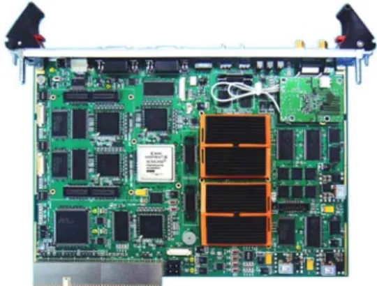
The GPS L1 and Galileo E1 combined receiver consists of an FPGA and DSP module for each signal processing board as shown in Fig. 2.
Figure 2. Combined L1/E1 Signal Processing board Configuration
In addition, if DSP process bit sync and demodulation module as described in reference test book[3], probability of tracking failure with acquisition was increased by the task processing delay. To solve this, the modules of DSP are tested and minimized for bit sync, demodulation, and integrator module. Finally, the function of DSP will be channel scheduling and floating operation module will be integrated into FPGA. To implement the signal processing, it is used two FPGA and two DSP as shown in Fig. 3.
Hardware Configuration
Firmware FPGA-2 Acquisition
Correlator Code NCO Carrier NCO Code generator Synchronization Demodulation Viterbi Decoding Observation Data FPGA-1
DSP-1
Integrator Discriminator
Loop filter Channel Management
DSP-2 Navigation Data
PVT Data transfer
Storage
cPCI connector
Figure 3. Combined L1/E1 Signal Processing board Configuration
. GPS L1/GALILEO E1 SIGNAL PROCESSING
Ⅲ
IMPLEMENTATION
1. Improved Signal Sensitivity
In order to increase accuracy of navigation solution in GPS L1 signal, a higher SNR(signal- to-noise ratio) is required by default. The tracking applies mainly synchronous integration between synchronous integration and non-synchronous
integration. Because current L1 receiver was usually limited to bit length for integration time of integrator module, the performance of L1 receiver was limited.[4] In this paper, the extended integration algorithm is applied in order to provide a more precise signal monitoring of GPS L1. The extended integration algorithm can increase integration time to bit length or more as Fig. 4.
+2 -2 +2 +2
Normal Integration
Extended Integration
+2+(-(-2))+2+2 = 8
Higher Amp.
Code Disc.
Code Disc.
+2 -2 +2 +2 Carrier Disc.
Carrier Disc.
Bit0
I
Bit3
Bit2
Bit1
+2 -2 +2 +2
I0
I1
I2 I3
+2+(-(-2))+2+2 = 8
Figure 4. Result Diagram of Extended Integration
The integrator in tracking accumulate 1ms correlation results in the L1 signal for fixed length.
The accumulated results are transferred to the code and carrier discriminator and have the value of positive or negative by bit unit. The code discriminator estimates and compensates error using amplitude difference of accumulated EPL correlation results. The carrier discriminator compensates error using phase of accumulated correlation results.
Therefore, if integration time is more than bit length, it can compensate reduction of accumulated amplitude using absolute value. The carrier discriminator should be maintained within 20ms for precise PLL. The code tracking loop has approximately 7dB SNR gain depending on increase of integration time as 20ms to 100ms.
Table 1. Code and Carrier tracking error for integration time Integration Time Code Tracking
Error
Carrier Tracking Error Code Carrier
20ms 20ms 17.8cm 2.3mm
100ms 20ms 10.3cm 1.9mm
100ms 40ms 10cm 2.1mm
2. Signal Acquisition result in weak signal environment
The goal of the acquisition is to find the visible satellites, the start of each C/A code and the Doppler shift fd. The C/A code is a code division multiple access(CDMA) system where a unique signal
is assigned to each satellite in the GPS system. In order to obtain the accurate pseudo range of the selected satellite, the starting time of the C/A code sequence in the received signal from the satellite must be accurately measured. The GNSS receiver applies correlation to measure this timing. The acquisition process performs two dimensional searching on the C/A code delay and Doppler frequency range. This is done by correlating the received signal by a logically generated code, then integrating the result. The acquisition is concluded if the integration result crosses a predetermined threshold. There have been many acquisition approaches that aim to reduce the processing time, increase the coherent integration, and/or avoid integrating across the unknown bit edges. The conventional hardware approach and searches for a satellite at each possible code delay and Doppler shift sequentially. Circular correlation uses Fast Fourier Transform (FFT) methods.[5] It calculates the correlation at all code delays at once, for each Doppler bin, so it runs much faster. The signal acquisition is based on search of the cross- correlation function maximum.
( ) ( ) ( )
( )
, , , , , * , , ,
I
D D D
T
I τ( f( ϑ( =
∫
s tτ f ϑ ⋅r tτ( f( ϑ( dt(1)
( )
ˆ, ˆ arg max , , ,
D D
D
f I f
f
τ τ ϑ
= τ ( ( (
( ( (2)
The two-dimensional space , must be observed. This two dimensional cross correlation function must be quantized in both domains from the implementation purposes. The selection of the quantization step ∆ in delay and frequency ∆
depends on the signal parameters, sampling frequency and on the other factors. In order to improve acquisition sensitivity of GPS L1 and Galileo E1 signal, integration time should be increased.[6]
The integration method can be divided into coherent and non-coherent integration. The coherent integration has large benefit than non-coherent integration. And its integrated length is limited by bit conversion. If coherent integration increase, the computation complexity increase by increased Doppler bins. The non-coherent integration doesn’t consider bit conversion by repetition squaring of
coherent integration result. But the squaring loss occurs by squaring of noise signal. Therefore, the acquisition should be designed with proper mixing of coherent integration and non-coherent integration.
To meet the –142dBm as acquisition performance level, it used two parameters such as coherent and non-coherent as shown in Table.2.
The FLL search range of tracking in GPS L1 signal has ±500Hz by Atan2 method. If the FFT size is 128 in acquisition, search bin is 125Hz and maximum Doppler error becomes ±62.5Hz.
Table 2. Parameter of Acquisition Sensitivity
Parameter GPS L1 Galileo E1
Coherent Num. 8 1
NonCoherent Num 20 15
Matched Filter Size 128 256
FFT Size 128 64
To get the –142 dBm at signal acquisition phase, combined integration of the coherent plus Noncoherent is applied as shown in table 2. we are proven the successfully acquisition operation described in figure 5.
Figure 5. Acquisition result in 142 dBm–
In case of Galileo signal processing, we consider that the Galileo E1 signal has longer code length than L1 code length and required SRAM capacity is increased for correlation results. Because its size exceeds SRAM capacity of board, the FFT size should be little and the precision Doppler estimation algorithm was added. The Galileo E1 signal has pilot signal and the FLL in tracking can apply Atan2 method. The FLL search range has ±125Hz for 4ms code length. Unfortunately, the bit conversion happen
before synchronization of secondary code in initial FLL and the actual FLL search range become
±62.5Hz as Atan method. Therefore, if FFT size has 64 in acquisition, search bin is 250Hz and maximum Doppler error becomes ±125Hz. In this case, Doppler error exceed tracking range and compensate Doppler error within ±62.5Hz using Doppler estimation algorithm.
3. Signal Tracking result in weak signal condition Signal tracking is the process that a receiver synchronizes the Galileo and GPS signal. Tracking module can configure the loop bandwidth, integration time, early-late chip spacing and correlator's number to use for tracking. The tracking loops consist of a delay lock loop (DLL) for tracking the code and a phase lock loop (PLL) to track the carrier. The code tracking block of the receiver is implemented using the method of Early-Late code tracking, that involves correlation with three different generated codes known as the early (E), the prompt (P), and the late (L) codes. To provide an input to the code generator, the outputs of correlators should be combined. To do that, the code phase of the generated PRN code will be properly adjusted. The input of code generator is computed through normalized early minus late envelope discriminator.
The carrier tracking block of the receiver is implemented as a Costas PLL.[7]
Figure 6. Tracking result in 152 dBm–
A PLL measures the carrier phase error and adjusts the frequency of the local oscillator based on that error. The input of local oscillator is computed through arctangent discriminator because of its high
accuracy and insensitivity towards navigation bit transitions. In order to improve tracking sensitivity, SNR and noise bandwidth is handled. The SNR can rise by longer integration time and/ noise bandwidth is reduced according to noise power in weak signal as the adaptive bandwidth algorithm. As shown in figure 6, the tracking is actually working in weak signal level such as 152 dBm. In weak signal mode– of tracking phase, any channel can not comply with the planning performance requirement.
. POSITION ACCURACY AND AVAILABILITY RESULTS
Ⅳ
Combined the GPS and Galileo system could be provide the high availability instead of GPS or Galileo only. Because it could be used more satellite than single system within the sky window to calculate the positioning information system availability will be increased. In this paper, GPS and Galileo Combined receiver unit can be processing the 51ch which consists of 24 channels for GPS and 27 channels for Galileo. To verify the functional operation of GPS and Galileo combined receiver unit, it will be used the GPS and Galileo Signal simulator which can be manufactured by SPIRENT company.
Detailed test environment is described in figure 7.
Figure 7. Functional Test Configuration
In Fig. 8, it can be used only GPS L1 signal processing.
Figure 8. Result of GPS L1 Signal Processing
In case of GPS L1 signal processing. we can get the positioning results such as 1.7 m for horizontal and 2.0 m for vertical individually. As a result of GPS and Galileo signal processing, positioning result are shown in figure 9. In the figure, red color mean the GPS L1 signal result and blue color mean the Galileo E1 signal processing result individually. To get the positioning result, the signal generated by RF simulator is used. To detailed clarify of positioning accuracy described in figure 9, we present the table 3.
Table 3. Positioning Result of using the signal produced by RF Simulator
Figure 9. Result of Combined GPS L1 and Galileo E1 signal processing
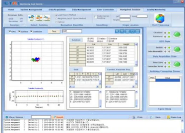
As a test result at real environment, we perform the receiver unit receive and process GPS L1 live signal from GPS satellites and also receive the Galileo E1 signal from RF simulator because the any Galileo satellite except the GIOVE-B satellite does not equipped in medium earth orbit. As shown in fig. 10, left side of window display the positioning test result.
Figure 10. Positioning result of Combination Signal Processing
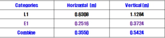
In the figure, blue color means the combination result such as GPS L1 and Galileo E1 signal result, green color and red color mean the Galileo E1 signal processing result and GPS L1 signal processing individually. To detailed clarify of positioning accuracy described in figure 10, we present the table 4.
Table 4. Positioning Result of using signal produced by GPS live signal and Galileo Simulator signal
In the table, the unit of accuracy is the root mean square(RMS). In case of testing of combined GPS L1 and Galileo E1 signal processing, the main reason of the positioning accuracy enhancement is more increase the available satellite number and also increase the available navigation signal
V. CONCLUSIONS
This paper presents the test results of the GPS and Galileo combined receiver which is manufactured on FPGA based signal processing board. Especially, by utilization of the FPGA property of the each GPS and Galileo signal processing, The advantage in using the FPGA hardware is to create a parallel structure that, in turn, increases the overall performance of the receiver at the same complexity cost. Also, in this paper, we presented algorithm optimization for performance of combined L1/E1 board. The application of extended integration algorithm in L1 signal can be compared with E1 receiver. In addition, the performance of combined L1/E1 board in weak signal satisfied ETRI requirement for acquisition sensitivity, tracking sensitivity, and tracking accuracy.
And finally we proposed the comparison navigation solution such as separated also combined the GPS L1 and Galileo E1 signal processing. According to the test result we proven that combined GPS and Galileo signal processing can be more higher accuracy and availability than GPS only system.
Reference
[1] Humphreys, T. E., Psiaki, M. L., Kintner, Jr., P.
M., Ledvina, B. M., "GNSS Receiver Implemetation
on a DSP: Status, Challenges, and Prospects"
19th international Technical Meeting, ION, Fort Worth, September, 2006.
[2] J. Bao and Y. Tsui, "Fundamentals of Global Positioning System Receivers A Software Approach," Willey, second edition, 2005.
[3] Kaplan, Elliot D., "Understanding GPS:Principles and Applications," Artech House.
[4] Van Nee, J.R. & Coenen, J.R.M., "New Fast GPS Code-Acquisition Technique Using FFT,"
Electronics Letters, Vol.27.2, Jan., 1991.
[5] Manandhar, D., Y. Suh, R. Shibasaki, "GPS Signal Acquisition and Tracking-An Approach towards Development of Software-based GPS Receiver," Technical Report of IEICE, ITS2004, July 16, 2004.
[6] Galileo Open Service, Signal In Space Interface Control Document, OS SIS ICD, Draft 1, ESA, European GNSS Supervisory Authority 2008.
[7] P.-L Normark, C. Stahlberg,“Hybrid GPS/Galileo Real Time Software Receiver,” Proceedings of ION GNSS 2005, Long Beach, Sept., 2005.
저 자
신 천 식 (CHEON SIG SIN) 정회원
년 월 한양대학교 전자공학과 1990 2 :
학사졸업
년 월 충남대학교 전자공학과 2000 2 :
석사졸업
년 월 현재 한양대학교 전자
2005 3 ∼ :
컴퓨터통신공학과 박사과정 년 월
1990 2 ∼현재 한국전자통신연구원 위성항법연구팀:
책임연구원
관심분야 위성통신 위성항법 위성궤도 주파수
< > , ,
이 상 욱 (Sanguk LEE) 정회원
년 월 연세대학교 천문기상학 1988 2 :
과 학사졸업
년 월 대학교 항공우주
1991 3 :Auburn
공학과 석사졸업
년 월 대학교 항공우주
1994 3 :Auburn
공학과 박사졸업 년 월 현재 한국전자통신연구원 위성항법연구팀장
1993 3 ∼ :
관심분야 인공위성 위성항법
< > ,
윤 동 원 (Dong Won YOON) 정회원 년 월 한양대학교 전자통신공 1989 2 :
학과 학사졸업
년 월 한양대학교 전자통신공 1992 2 :
학과 석사졸업
년 월 한양대학교 전자통신공 1995 8 :
학과 박사졸업
년 월 년 월 동서대학교 전임강사
1995 3 ∼1995 8 :
년 월 년 월 대전대학교 부교수
1997 9 ∼2004 2 :
년 현재 한양대학교 전자컴퓨터통신공학부 교수
2004 ∼ :
관심분야 무선통신 이동통신 위성 및 우주통신
< > , ,