Thermodynamic Analysis on Heat Recovery System of Hermetic Gas Hood for Paper Machine
Yan Yan
1†, Dong Jixian
2Received March 16, 2020; Received in revised form April 15, 2020; Accepted April 18, 2020
ABSTRACT
The working condition of hot air exchange system dramatically affects the operational status of the paper machine dryer, energy saving efficiency and paper quality of dryer section. After analyzing the heat recovery method and energy-saving effect of the closed air hood, it is found that the current process is limited by the design of the heat ex- changer and the control system, and usually the preheated fresh air in the first-stage heat recovery device only recovers the sensible heat in the exhaust air of the air hood.
Therefore, the common heat recovery process has been adjusted in this paper. The fresh air is firstly heated by latent heat with relatively low temperature in the exhaust gas, and then the sensible heat with relatively high temperature in the exhaust gas is recovered.
The energy saving effect is calculated through an example. The calculation results show that this process can save about 20% energy compared with the original process.
Keywords: Heat recovery, air hood, latent heat, theoretical calculation, energy saving
Printed in Korea http://dx.doi.org/10.7584/JKTAPPI.2020.04.52.2.61
1 College of Mechanical and Electrical Engineering, Xi’an Polytechnic University, Xi’an, Shaanxi Province, 710600, People’s Republic of China, Lecturer
2 College of Mechanical and Electrical Engineering, Shaanxi University of Science & Technology, Xi’an, Shaanxi Province, 710021, People’s Republic of China, Professor
† Corresponding Author: E-mail: [email protected] (Address: College of Mechanical and Electrical Engineering, Xi’an Poly- technic University, Xi’an, Shaanxi Province, 710600, People’s Republic of China)
1. Introduction
The paper industry is one of the important basic raw material industries of the national economy.
The consumption level of paper and paperboard has become an important indicator of the level of modernization and civilization of a country.1) With
the rapid development of news publishing, book pr.inting, and other industries, the demand of the paper industry continues to expand. It is expected that by 2030, the global paper and cardboard out- put will increase to 500 million tons.2)
Papermaking is not only a high-input economy industry, but also a high-energy input industry. It
is a large consumer of energy and gas.3) Compre- hensive energy consumption of paper is about 1.55 to 1.70 tons of coal. Steam energy consumption accounts for more than 15% of the cost of paper- making. The dryer section is the main ener- gy-consuming section in papermaking process.
Although the amount of water removed by the dryer section is only 1-2% in the entire papermak- ing process, its energy consumption is more than 10 times of the press section and 7 times of the forming section.4) Therefore, how to reduce the energy consumption in the dryer section is not only the key to energy saving of the paper machine, but also the key to reducing the energy consumption of the entire paper mill.
The internal and external contributions for drying are 65% and 35%, respectively. Therefore, the cur- rent research focuses on the improvement of the interior of the dryer, such as using multi-channel dryer to improve the drying efficiency,5-8) or intro- duction of heat pump to increase the amount of flash steam in order to reduce the amount of fresh steam.9,10) However, there are relatively few studies on the steam heat recovery systems.
With the increase of energy saving and emission reduction requirements, researches should not only focus on the energy-saving reform of the hydro- thermal system, but also on the energy saving outside the dryer. The dryer hood is the primary facility of the ventilation system in the dryer sec- tion of the multi-cylinder paper machine. The types of hoods (open hoods, semi-closed hoods and closed hoods) play a decisive role in the selection of ventilation devices and heat recovery devices in the hot air exchange system, so the development of the air hood actually reflects the development of the entire hot air exchange system in the dryer sec- tion. The high-humidity closed air hood can form a relatively closed space outside the dryer, and the temperature and humidity in the space remain rel- atively stable. Therefore, the ineffective heat dis-
sipation loss on the surface of the drying cylinder can be reduced, and the steam consumption can be saved. Meanwhile, the exhaust air temperature and moisture content are both high, thus creating conditions for exhaust air heat recovery.
In recent years, the research on the hot air sys- tem of the air hood is still less than that of the dryer, and the only researches are also mainly focused on the design of the zero pressure of the hot air system of the air hood or the control sys- tem,11) the research on the heat recovery and utili- zation efficiency of the hot air system is very few,12) especially on the thermodynamic analysis. There- fore, this paper analyzes the amount and grade of the energy recovered by various parts in the exist- ing commonly used secondary recovery process, and analyzes its energy saving effect in combina- tion with the new process flow.
2. Closed Air Hoot Hot Air Exchange System
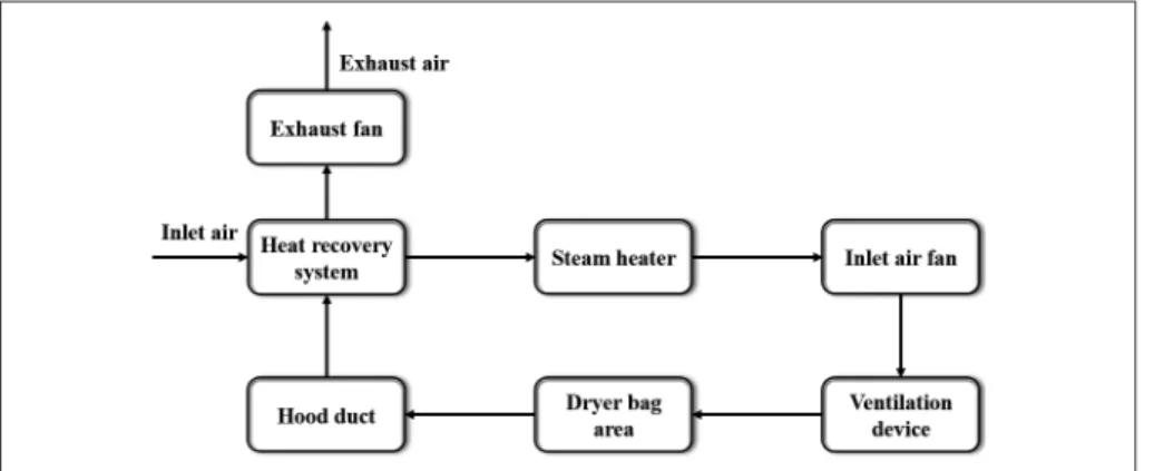
The hot air exchange system in the dryer section mainly includes air hood collection, hot air energy recovery, inlet and exhaust air and inlet air heat- ing, as shown in Fig. 1. The paper passes through the drying section, reducing its water content from 60-70% to about 5%. According to the basic prin- ciple of heat and moisture exchange, under the same moisture content, the relative humidity and the heating temperature required by the dryer are decreased with the inlet air temperature increase, and the mass transfer speed from paper to envi- ronment will also accelerate. The higher the rela- tive humidity of exhaust air, the more water vapor will be carried away. However, the inlet air tem- perature is affected by heat loss, heating capacity, production safety and other factors. When the humidity of exhaust air is too high, it is easy to cause local heat exchange between paper wool and
Fig. 1. Hot air exchange system of drying section.
water vapor in the air, and the precipitated liquid water forms paper scars and falls on the paper surface, affecting the product quality. At present, the internationally popular design parameters are the inlet air temperature of 95 to 110℃, the exhaust air temperature is 78 to 85℃, and the dew point temperature is 58 to 62℃. For a paper machine with an annual output of 100,000 tons, the exhaust air volume of the closed air hood is about 1.5×10⁵ kg/h (different paper types have different paper opportunities), and the enthalpy in the exhaust air per hour is about 7.6×10⁷ kJ, which is equivalent to the condensation heat of 33 tons of steam. Since its enthalpy value is quite considerable, direct exhaust will cause a great waste of energy. Therefore, the exhaust air should be heat-recovered.
At present, the exhaust air mostly adopts a three-stage heat recovery method. The first-stage heat recovery device uses an air-to-air heat exchanger, which uses the exhaust air to directly preheat fresh air from the environment. After heat recovery, the temperature of the fresh air can usually be increased to about 55-60℃, and the exhaust air temperature is reduced to 60-65℃.
The second-stage heat recovery device uses a gas-liquid heat exchanger, and the cold water heated by it is used for cleaning blankets or heat
other process water. After this stage of recovery, the exhaust air temperature will reduce to 40-45℃. The third-stage recovery is mainly used in cold areas to preheat the fresh air entering the workshop, but in other seasons, the third-stage heat recovery device is not necessary.
3. Thermodynamic Analysis of Air Hood Hot Air Energy Recovery
The enthalpy of the hood exhaust air is very high, but its heat is mainly stored in the water vapor contained in the air. Assuming that the ambient temperature is 35℃, the ambient moisture content is 14 g/kg (A), the exhaust temperature is 80℃, and the relative humidity of the exhaust air is 40%, the two-stage heat recovery method is used. The technological process is shown in Fig. 2, in which the outlet temperature of the first-stage exhaust air is 60℃, the outlet temperature of the sec- ond-stage exhaust air is 45℃. The wet air param- eters at the process point for the first and second stage heat recovery are given in Table 1. It can be seen from the table that the first-stage is mainly recovered the sensible heat, with a recovery capacity of 25.5 g/kg (A), while the second-stage is mainly recovered as the latent heat, with a total
recovery capacity of 227.3 kJ/kg (A), of which the latent heat recovery is 201.4 kJ/kg (A), accounting for 89% of the total recovery capacity. Obviously, when the exhaust air temperature decreases to the ambient temperature, the exhaust air energy is fully recovered, but compared with the ambient air, the enthalpy of humidity is still not fully recovered.
It also can be seen from Table 1 that the first- stage heat recovery energy accounts for 7.6% of the theoretical recoverable amount, the second- stage accounts for 67.4%, and the remaining energy is 25%. From the change of relative humid- ity, it can be found that all the first stage recovery is the sensible heat of the air, so the energy is low,
and the heating capacity for fresh air is limited. If the recovery temperature of exhaust air is further reduced during the first-stage of recovery, the vapor contained in air will be condense to release heat so that the preheating temperature of fresh air will be higher, thus saving the flow rate of subsequent steam and reducing the cost.
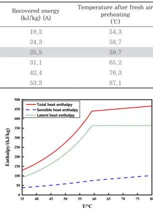
Assuming that the mass flow of fresh air and exhaust air is the same, according to the parame- ters given in Table 1, the recovered energy at dif- ferent exhaust air temperatures of the first stage and the outlet air temperature of fresh air pre- heated by the first stage are calculated. The results are shown in the Table 2.
As can be seen from Table 2, when the tempera- Table 1. Parameters of two-stage recovered wet air
Position Temp.
(℃)
Moisture (g/kg) (A)
Relative humidity
(%)
Total heat enthalpy (kJ/kg) (A)
Sensible heat enthalpy (kJ/kg) (A)
Latent heat enthalpy (kJ/kg) (A)
1 80 145.6 40.0 466.3 102.1 364.2
2 60 145.6 95.2 440.8 76.6 364.2
3 45 65.1 100 213.5 50.7 162.8
4 35 14.0 39.6 71.1 36.1 35.0
- 35 36.6 100 129.1 36.1 93.0
Fig. 2. Schematic of heat recovery for closed gas hood.
ture of the first-stage exhaust air increases, since the recovered energy comes from the sensible heat of the air, and assumption that the exhaust air and fresh air flow are the same, the temperature of the fresh air after preheating will decrease by 1℃ if the exhaust air temperature basically rises by 1℃.
However, when the temperature of the exhaust air decreases, the situation will be very different. At this time, the air enters a completely saturated state, water vapor is separated out, and a large amount of heat is released. Only according to the equilibrium relationship, the temperature of fresh air after preheating will increase sharply. For example, the exhaust air will only decrease by 0.5℃, while the change range of fresh air preheat- ing temperature is close to 10℃. Especially as shown in the last column in Table 2, when the exhaust air temperature is reduced to 58℃, the fresh air recovery temperature is even higher than the exhaust air temperature of the first-stage recovery inlet, which is obviously impossible to achieve. The reason is that, when the air enters the saturated state, the change in latent enthalpy with temperature is much larger than in sensible enthalpy. Fig. 3 shows the relationship between enthalpy and temperature in the exhaust. It can be seen from the figure that the latent heat enthalpy does not change when the temperature is higher than 59.2℃, while the latent heat enthalpy decreases sharply when the temperature is lower than 59.2℃. The sensible enthalpy changes linearly
throughout the temperature range.
After entering the saturation state, a slight change of the exhaust temperature in the first stage will cause sharp change of the heat recovery temperature, which not only puts forward high requirements on the design of the heat exchanger, but also most importantly causes difficulty in sta- ble control. Therefore, in current heat recovery systems, only sensible heat is basically recovered from the first stage, while latent heat is recovered from the second stage. Although the total energy of latent heat is large, the quality is not high, and most of the processes cannot fully utilize so much latent heat. Therefore, from the perspective of thermodynamics, this recovery scheme is not opti- mal because a large amount of latent heat with low quality is not available, while fresh air with Table 2. Parameters of exhaust temperature and hood
First stage exhaust temperature
(℃)
Exhaust relative humidity (%)
Recovered energy (kJ/kg) (A)
Temperature after fresh air preheating
(℃)
65 76.8 19.2 54.3
61 92.0 24.3 58.7
60 95.2 25.5 59.7
59 100 31.1 65.2
58.5 100 42.4 76.3
58 100 53.3 87.1
Fig. 3. Effect of temperature on enthalpy in exhaust air.
35 40 45 50 55 60 65 70 75 80
0 50 100 150 200 250 300 350 400 450 500
Enthalpy/(kJ/kg)
T/℃
Total heat enthalpy Sensible heat enthalpy Latent heat enthalpy
relatively low temperature is preheated by high- temperature exhaust air, resulting in large heat exchange temperature difference and large energy quality loss.
4. Hot Air Energy Recovery Process and Calculation of Air Hood
Based on the above analysis, it would be more reasonable if fresh air from the environment with relatively low temperature is first heated by latent heat in the exhaust air and then further heated by sensible heat with better quality. Based on this idea, while considering the difficulty of designing the heat exchanger and control system, a heat recovery process as shown in Fig. 4 is proposed. Different from process in Fig. 2, a gas-gas heat exchanger is added to the first-stage heat recovery.
The high-temperature exhaust gas from the air cover passes through the sensible heat exchanger first, then a small amount of the exhaust gas enters the latent heat exchanger, and the rest of the exhaust gas enters the second-stage heat
recovery. The fresh air from the environment first exchanges heat with the exhaust gas in the latent heat exchanger. During the heat exchange process, the temperature is gradually reduced due to the small flow rate of exhaust gas in the latent heat exchanger, and the latent heat in the air is gradu- ally released to heat fresh air, so that the tem- perature of fresh air will not change sharply due to the slight change of exhaust air temperature. The fresh air coming out of the latent heat exchanger already has a high temperature, then will be fur- ther heated by the high-temperature exhaust gas.
Finally, the temperature of the fresh air which is discharged from the first-stage heat recovery sys- tem can approach the exhaust temperature of the hood. In this process, the gas energy is used step by step according to the temperature and quality, the heat exchange temperature difference between the latent and sensible heat exchanger is small, and the heat exchange loss can be greatly reduced.
The thermodynamic calculation of the first stage heat recovery device is carried out in combination with a specific process flow. The thermal parame- ters at each point of the drying cylinder and flash
Fig. 4. Schematic of improved closed air hood heat recovery system.
tank are shown in Fig. 5, other parameters can be found in article of Choi et al.4)
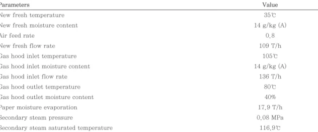
Design parameters of the calculation examples were given in Table 3. In order to simplify the analysis, it is believed that the first stage heat exchanger in the original process and the sensible heat exchanger in the new process can recover all sensible heat, that is, the relative humidity of the exhaust outlet reaches 100%. Considering that the energy consumption of the boiler will increase while the fresh air is heated by the condensed water from the low temperature section, so only the secondary steam from the medium temperature section will be reused, and the energy of the sec- ondary steam only considers the latent heat part,
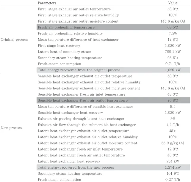
without considering overheating and subcooling energy. The insufficient energy is provided by the primary steam. The calculation results of the new and old processes are shown in Table 4.
It can be seen from the table that the new process can recover part of the latent heat first, and then recover the sensible heat. Compared with recover- ing sensible heat only, the preheating temperature of the fresh air can be increased by 8.3℃, and the additional heat recovery is 254 kW, an increase of 19.9%. Only 3% of the exhaust air from the sensible heat exchanger outlet can satisfy the preheating of fresh air in the latent heat exchanger, thus having little influence on the secondary heat recovery.
Fig. 5. Schematic of thermodynamic system.
V-1
Ⅰ # Dryer
E-2
Ⅱ # Dryer
V-6
E-4 E-5
Ⅲ # Dryer
V-7
Fresh steam 0.5MPa
Condensation water tank To the hot air
system
11365kg/h
0.3MPa 6837kg/h
0.08MPa 670kg/h
0.03MPa E-3
Ejector
Flash tank0.17MPa 0.08MPa 0.03MPa
15284kg/h 1247.56kg/h
Flash tank
Flash tank
Table 3. Example design parameters
Parameters Value
New fresh temperature 35℃
New fresh moisture content 14 g/kg (A)
Air feed rate 0.8
New fresh flow rate 109 T/h
Gas hood inlet temperature 105℃
Gas hood inlet moisture content 14 g/kg (A)
Gas hood inlet flow rate 136 T/h
Gas hood outlet temperature 80℃
Gas hood outlet moisture content 40%
Paper moisture evaporation 17.9 T/h
Secondary steam pressure 0.08 MPa
Secondary steam saturated temperature 116.9℃
5. Conclusions
It is found that, in order to facilitate the design of heat exchangers and control systems, only sensible heat from exhaust gas is recovered as the first stage heat recovery through the analysis and ther- modynamic estimation of the existing sealed hood heat recovery system process. Although the latent heat can be recovered by the second stage heat recovery, the amount of latent heat is large and
the grade is low, which causing a certain waste.
In this paper, the process of the first-stage heat recovery is adjusted and divided into two parts:
sensible heat recovery and latent heat recovery. The exhaust flow rate is small during latent heat recov- ery, which is convenient for achieving stable control when the process parameters change. The calcula- tion example shows that the first stage of the new process can recover 19.9% more energy and has lit- tle influence on the second stage heat recovery.
Table 4. Comparison of calculation results of original process and new process
Parameters Value
Original process
First-stage exhaust air outlet temperature 58.9℃
First-stage exhaust air outlet relative humidity 100%
First-stage exhaust air outlet moisture content 145.6 g/kg (A)
Fresh air preheating temperature 68.5℃
Fresh air preheating relative humidity 7.5%
Mean temperature difference of heat exchanger 17.8℃
First stage heat recovery 1,020 kW
Latent heat of secondary steam 766.1 kW
Secondary steam heating temperature 93.6℃
Fresh steam consumption 0.71 T/h
Total energy recovered from the original process 1,020 kW
New process
Sensible heat exchanger exhaust air outlet temperature 58.9℃
Sensible heat exchanger exhaust air outlet relative humidity 100%
Sensible heat exchanger exhaust air outlet moisture content 145.6 g/kg (A) Sensible heat exchanger fresh air inlet temperature 43.3℃
Sensible heat exchanger fresh air outlet temperature 76.8℃
Mean temperature difference of sensible heat exchanger 9.5
Sensible heat exchanger heat recovery 1,020 kW
Exhaust air passing through latent heat exchanger 3%
Exhaust air flow through the submersible heat exchanger 4.1 T/h Latent heat exchanger exhaust air outlet temperature 45℃
Latent heat exchanger exhaust air outlet relative humidity 100%
Latent heat exchanger exhaust air outlet moisture content 65.9 g/kg (A) Latent heat exchanger fresh air inlet temperature 12.9℃
Latent heat exchanger fresh air outlet temperature 43.3℃
Latent heat exchanger heat recovery 254 kW
Total energy recovered from the new process 1,274 kW
Secondary steam heating temperature 101.9℃
Fresh steam consumption 0.27 T/h
Furthermore, the energy saving potential of the new process mentioned will increase with the moisture content in the exhaust gas increase. In addition, the new process may affect the design and control of heat exchangers, the increase of equipment cost and the difficulty of operation.
These works need to be further studied in subse- quent works.
Acknowledgement
This work was supported by the National Natural Science Foundation of China (grant number 51375286), the special scientific research of Shaanxi Provincial Department of Education (grant number 19JK0374), Xi’an Polytechnic University (grant number BS201807) and Xi’an key laboratory of modern intelligent textile equipment (grant number 2019220614SYS021CG043).
Literature Cited
1. Paper & Board Production, Consumption, Development Direction in Japan, Japanese paper industry: Research and Prospects in 2017&2018, China Pulp & Paper 37(8):72-79 (2018).
2. Shen, K. and Fang, G., Thirty years of devel- opment of the world paper industry and forecast of China’s paper and paperboard production and consumption in 2030, JiangSu ZaoZhi 30(4):
2-8 (2017).
3. Chen, C. and Qiu, R., Estimation of energy consumption and carbon emissions of China’s pulp & paper industry, China Pulp & Paper 33(4):56-62 (2014).
4. Choi, S. U. S., Yu, W., Wambsganss, M. W., Chien, T.-H., Harkness, J., France, D. M.,
Barde, D. K., Vallance, W. D., Stewart, C. W., and Timm, J. L., Design and demonstration of multiport cylinder dryer: Final report on the multiport dryer project in phase 1, Argonne National Laboratory, IL, USA (2001).
5. Dong, J., Zhang, Z., and Lu, J., Structure and heat transfer mechanism of energy-saving multi-channel dryer, Paper and Paper Making 30(2):4-10 (2011).
6. Yan, Y., Dong, J., and Wang, B., Condensa- tion heat transfer characteristics and flow regime in a horizontal rectangle channel of a multichannel cylinder dryer, Drying Technol- ogy 36(1):118-127 (2018).
7. Yan, Y. and Dong, J., Effect of aspect ratio on steam condensation heat transfer characteris- tics and flow pattern in rectangular channel, Journal of Chemical Industry and Engineering 69(9):3851-3858 (2018).
8. Yan, Y., Dong, J., and Tang, W., Visualization study of steam condensation in rectangular channel of multichannel cylinder dryer, Jour- nal of Heat Transfer 139(5):054503 (2017).
9. Zhang, X., Luo, Z., and Yan, E., Study and application of low steam pressure heat pump heat supply system in dry section of paper machine, China Pulp & Paper 28(11):6-14 (2009).
10. Tang, W., and, Yi, Z., Application of absorp- tion heat transformer in paper machine drying section, China Pulp & Paper 38(10):43-50 (2019).
11. Tang, W., Zhou, Y., and Wang, X., Design of closed air hood control system for cardboard machine, China Pulp & Paper 31(07):38-46 (2012).
12. Yao, X., Research on energy-saving control of hot air exchange system in drying section of paper machine, Master’s Thesis, Nanjing For- estry University, China (2010).