• 검색 결과가 없습니다.

Modeling and Energy Management Strategy in Energetic Macroscopic Representation for a Fuel Cell Hybrid Electric Vehicle

N/A
N/A
Protected

Academic year: 2021

Share "Modeling and Energy Management Strategy in Energetic Macroscopic Representation for a Fuel Cell Hybrid Electric Vehicle"

Copied!
11
0
0

로드 중.... (전체 텍스트 보기)

전체 글

(1)

ISSN(print) 2671-7972 ISSN(online) 2671-7980 http://dx.doi.org/10.7839/ksfc.2019.16.2.080

Modeling and Energy Management Strategy in Energetic Macroscopic Representation for a Fuel Cell Hybrid Electric Vehicle

To Xuan Dinh 1,2 , Le Khac Thuy 2 , Nguyen Thanh Tien 2 , Tri Dung Dang 1 , Cong Minh Ho 1 , Hoai Vu Anh Truong 1 , Hoang Vu Dao 1 , Tri Cuong Do 1 and Kyoung Kwan Ahn 3,*

Received: 05 Apr. 2019, Accepted: 24 May 2019

Key Words:Hybrid Vehicle, Proton Exchange Membrane Fuel Cell, Energy Management, Energetic Macroscopic Representation.

Abstract: Fuel cell hybrid electric vehicle is an attractive solution to reduce pollutants, such as noise and carbon dioxide emission. This study presents an approach for energy management and control algorithm based on energetic macroscopic representation for a fuel cell hybrid electric vehicle that is powered by proton exchange membrane fuel cell, battery and supercapacitor. First, the detailed model of the fuel cell hybrid electric vehicle, including fuel cell, battery, supercapacitor, DC-DC converters and powertrain system, are built on the energetic macroscopic representation. Next, the power management strategy was applied to manage the energy among the three power sources. Moreover, the control scheme that was based on back-stepping sliding mode control and inversed-model control techniques were deduced. Simulation tests that used a worldwide harmonized light vehicle test procedure standard driving cycle showed the effectiveness of the proposed control method.

* Corresponding author: kkahn@ulsan.ac.kr

1 Graduate school of Mechanical Engineering, University of Ulsan, Nam-gu, Ulsan 44610, Korea

2 Department of Electrical Engineering, Le Quy Don Technical University, 236, Hoang Quoc Viet street, Hanoi, Vietnam

3 School of Mechanical Engineering, University of Ulsan, Ulsan, Nam-gu, Ulsan 44610, Korea

Copyright Ⓒ 2019, KSFC

This is an Open-Access article distributed under the terms of the Creative Commons Attribution Non-Commercial License(http://

creativecommons.org/licenses/by-nc/3.0) which permits unrestricted non-commercial use, distribution, and reproduction in any medium, provided the original work is properly cited.

1. Introduction

The important of reducing air pollution and the oil crisis has activated the research for electrochemical energy systems 1-3) . Among them, fuel cells provide a high-efficiency power generation and is an interesting solution to produce near zero emission electricity in automotive vehicles and construction vehicles. Thanks to the low operating temperature and pressure, proton exchange membrane fuel cell (PEMFC) become the

most practical fuel cell system in fuel cell hybrid electric vehicle (FCHEV). In addition, the main fuel of the PEMFC, hydrogen, can be produce using renewable energy sources, which is zero emission. Since fuel cell has slow dynamic characteristic, a fuel cell combined with battery and supercapacitor for the power sources of the FCHEV have been developed recently. Therefore, the energy management which determines the power distribution between the fuel cell system and auxiliary energy storage devices is a significant technique 4-8) .

The FCHEV current energy conversion system converts the electrochemical energy to electrical energy and mechanical energy by using many components.

Therefore, such a complex system and its control

strategy require a simple representation of the whole

system by taking into account the integrality and

physical causality between components. Meanwhile,

EMR is a graphical description of the system, which

allows an easy design of the control algorithm 9) . The

EMR have been introduced at the University of Lille in

France in 2000 and have been utilized in many works

(2)

for representation, modeling, and management of various systems such as wind energy conversion system 10) , hybrid vehicle 11) , marine current turbine system 12) .

In order to realize the control signal for the FCHEV, a backtepping sliding mode algorithm is firstly applied to track the reference speed of the vehicle and demanded power of the system. As a widely used nonlinear control method, sliding mode control (SMC) features outstanding performance and robustness. SMC is based on a high frequency switching control law that drives the system’s trajectory onto a designed hyperplane in the state space to achieve desired performance. Meanwhile, backstepping technique starts the design process in feedback form and derive controllers that stabilize each subsystem step by step using Lyapunov technique. The combination of the SMC and backstepping technique is to develop a global stable controller for the FCHEV system based on Lyapunov theory.

Fuel cell Stack Gas Tank

Battery Super-

capacitor

DC Link

Motor Control System

Motor/

Generator

Gear tranmission

DC/DC Converter

DC/DC Converter DC/DC

Converter

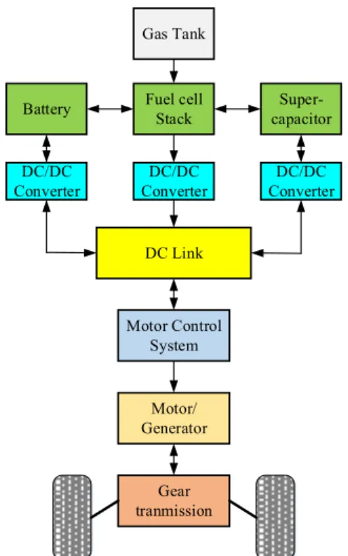
Fig. 1 Fuel cell hybrid electric vehicle configuration

In this work, an EMR representation of the overall fuel cell hybrid electric vehicle system is proposed. In addition, an energy management strategy (EMS) is developed to manage the power distribution between fuel cell and energy storage devices. Basing on the

reference values obtained from EMS, the whole control structure is then derived, using backstepping sliding mode control technique and inversion rules.

The rest of this paper can be organized as follows.

The electrical vehicle modeling is presented in Section II. The EMR of the system, EMS and control algorithm are described in Section III. The simulation results of the comparative controllers are given in Section IV.

Finally, the conclusion is presented in Section V.

2. Studied fuel cell hybrid electric vehicle modelling

The proposed system structure of fuel cell hybrid electric vehicle is shown in Fig. 1. The system comprises of three subsystems: the energy storage system, the power bus, and the traction subsystem. The energy storage system is a hybridization of the batteries, supercapacitors, and a PEMFC. In this structure, the fuel cell system is designed as a primary power source for the vehicle propulsion. The battery and supercapacitor jointly provide additional power when the vehicle starts, accelerates, or climbs the slope. The power bus is a DC bus between energy sources and load. Both battery and supercapacitor parallelly connect to the DC bus by the corresponding bidirectional DC-DC converters. Meanwhile, the fuel cell system parallelly connects to the power bus by a boost DC-DC converter. The advantage of this structure is that the supercapacitor can provide the peak power and recover braking energy so that it reduces the load on fuel cell and battery. In addition, since it also provides a long lifetime for the battery by less charging and discharging.

Fuel

Excess fuel

Oxygen

Water H +

H + H +

Load

Fig. 2 Fuel cell stack system

(3)

2.1 Fuel cell model

The PEMFC model consists of three sub-model: the electrochemical model, the electric model, and the fluidic model. The electric model represents the capacitive behavior of the fuel cell, while the electrochemical model shows the strictly speaking fuel cell and the fluidic model represents the operation of the gas supply. The working principle of the PEMFC is as the following. Firstly, hydrogen is supplied to the anode, which catalytically dissociates into protons and electrons. The newly formed protons migrate through the polymer electrolyte membrane to the cathode and the electrons travel along an external load circuit to the cathode side to create the current output of the fuel cell. The environment air which contains oxygen, is delivered to the cathode side. As soon as the protons, oxygen, and the electrons arrive at the cathode side, they combine to form water. Electricity and heat are then created.

To derive the modeling of the fuel cell system, the following assumptions are given:

1) The hydrogen is totally used, and the hydrogen pressure is constant

2) The stack temperature and humidity in the cathode are well controlled and the water inside cathode is only vapor phase.

3) The stack voltage only has activation losses, that is the losses due to the slowness of chemical reactions at electrode’s surfaces.

4) The current dynamics of the motor which drives the hydrogen compressor is negligible.

2.1.1 Electrochemical sub-model

The electrochemical sub-model is represented by a controlled voltage source in series with a constant resistance. The activation losses are modelled electrically by a paralleled RC branch, which cause the delay in fuel cell voltage as there is a sudden change in stack current.

The controlled voltage E is calculated by the following equation.

 

ln / 3 1

oc c T f o r

E E   N E i i sT  (1)

where E oc denote open circuit voltage; N c the number of cells; E T the Tafel slope; i f and i o the fuel cell current and exchange current, respectively; s the Laplace transform variable; T r the response time at 95% of the final value. The first order transfer function 1/(sT d /3+1) represents the delay of controlled voltage due to the activation losses.

In order to obtain the open circuit voltage, the following Nernst equation is employed, which allow us to calculate the potential that will be formed across the membrane based on the valence and concentration gradient of the ion. In general, the Nernst voltage, the exchange current, and the Tafel slope depend on gases pressures, temperatures, compositions, and flow rates 13) . Thus, for the following electrochemical reaction of the fuel cell system

2 2 2

1

H  2 OH O

(2) the Nernst voltage is determined as the following.

 

2   2 2

2 2

sat 0.5

sat 0.5

ln 373.15

2

ln 373.15

2

f

H O

n

f H O

H O

G RT P T T K

F zF P P

E G RT P T P

T K

F zF P P

  

       

  

                (3)

where E n is the Nernst voltage, R denotes the universal gas constant, T is the temperature of operation in Kelvin, F denotes the Faraday’s constant, z is the valence of the ionic species. P sat (T) denotes the saturation pressure of water at temperature T, which is calculated as the following.

    2

10

5 2 7 3

log 2.18 2.95 10

9.18 10 1.45 10

P sat T T

T T

    

    (4)

Hence, the Nernst voltage is rewritten as follows

 

 

 

2 2

2 2

2 0.5

0.5

44.43 1.229 298.15

ln 373.15

44.43 1.229 298.15

ln 373.15

H O n

H O H O

T zF

RT P P T K

E zF

T zF

RT P P

T K

zF P

   

 

   

      

  

     

    

(5)

(4)

The open circuit voltage is calculated as the following.

oc c n

EK E (6)

where K c is the voltage constant at nominal condition of operation.

In addition, the exchange current i o and the Tafel slope are given as

 2 2 

H O RT G

o

zFk P P

i e

Rh

 

 (7)

T

E RT

zF

 (8)

where α denotes the charge transfer coefficient, P H2 , P O2 , and P H2O are in turn the partial pressure of hydrogen, oxygen inside the stack and partial pressure of water vapor.

2.1.2 Fluidic sub-model

The fluidic model is the gas circuit placed between the reaction sites and the gas tanks. The partial pressures of hydrogen, oxygen and water vapor are determined by the following equations

E OB

R B1

C B1

R B0

U B1

u B

+

- R B2

C B2

U B2 U B0

i B

Fig. 3 Equivalent circuit model of battery.

 

 

 

2 2 2

2 2 2

2 2 2

1 1

2

H fH H f

O fO O a

H O w O fO a

P U r P

P U r P

P r r U P

 

 

 

(9)

where P f and P a are absolutely supply pressure of fuel and air, respectively, r H2 and r O2 are the percentage of hydrogen in the fuel and percentage of oxygen in the oxidant, respectively, r w is the percentage of water vapor in the oxidant, U fH2 and U fO2 are the rates of utilization of hydrogen and oxygen, respectively, which

are calculated as follows

2

2

2

2

60

60 2

fc fH

f f H fc fH

a a O

U RTi

zFP q r U RTi

zFP q r

(10)

where q f and q a are the fuel flowrate and air flowrate, respectively.

2.1.3 Electric sub-model

The fuel cell voltage u f is given as follows:

f i f

u   E R i (11)

where R i is the internal constant resistance. The term R i i f represents the loss due to electrolyte resistances.

2.2 Battery model

The most general models for battery in an electrical vehicle can be divided into two groups: electrochemical models and the equivalent circuit models 14-18) . In this work, an equivalent circuit model called dual polarization (DP) model is adopted to describe the behavior of the battery. The schematic diagram of the DP model is shown in Fig. 3. Following this model, the corresponding equation of the battery model can be given as the following.

1 1

1 1 1

B B

B

B B B

U i

U    R CC (12)

2 2

2 2 2

B B

B

B B B

U i

U    R CC (13)

1 2 0

B OB B B B B

uEUUi R (14)

2.3 Supercapacitor model

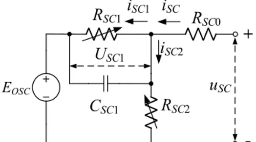
Similar to the battery models, supercapacitor modeling methods can be summarized as two kinds:

electrochemical models with high precision but complex

computation 19,20) , and equivalent circuit models 21,22) ,

which provide a trade-off between precision and

complex computation. In this work, an electrical

equivalent circuit model of supercapacitor is employed

(5)

E OSC

i SC1 i SC

i SC2

R SC1

C SC1

R SC0

R SC2

U SC1

u SC

+

- Fig. 4 Equivalent circuit model of supercapacitor

as shown in Fig. 4. The modelling equations of the supercapacitor based on Kirchoff’s voltage and current laws are then derived as follows 23)

1

1 1 1

1

( ) ( ) ( )

SC

SC SC SC

SC

U t

C U t i t

R    (15)

 

1

2 2

SC OSC ( )

SC SC

U t E

i t R

  (16)

0 ( ) 1 ( ) ( )

OSC SC SC SC SC

ER i tU tu t (17)

1 2

( ) ( ) ( )

SC SC SC

i ti ti t (18)

where U SC1 (t) and v SC (t) denote the voltage drop across the capacitor C SC1 and the supercapacitor’s voltage, respectively, E OSC the open circuit voltage which represents the relationship between stored charge and the supercapacitor’s voltage u SC , i SC (t) the terminal current, R SC0 the constant resistor, R SC1 and R SC2 the variable resistor which are given as the following.

  2  

1 1 , 2 3

SC SC SC SC SC SC

R v   v R v   v (19)

where λ 1 , λ 2 , and λ 3 are constants parameters. Taking into accounts of the leakage effect, the state of charge (SOC) of the supercapacitor is calculate as

 

4 2

SC i SC i SC

      (20)

where δ SC is the SOC of the supercapacitor, λ 4 =1/

(3600C SC ) with C SC is the capacity in Ampere-hours.

2.4 DC-DC converter

It is supposed that the time constant of the inductor

is much greater than the switching period of the DC-DC converter and the modulation frequency is sufficiently high to consider an average model 24) , thus the switching of the converter does not affect to the dynamics of the currents. Then the model of the DC-DC converter shown in Fig. 5 can be given as follows 24,25)

L

I h L L

V V L di i R

  dt  (21)

h O

V   V (22)

Fig. 5 Equivalent circuit model of DC-DC converter.

Fig. 6 Hybrid energy system in the electric vehicle.

1, for boost converter or for

bidirectional converter with 0 1, for bidirectional converter with 0

O L

O O O O

i i

i V i V

  

  

    

(23)

where V I , V O are the input voltage and output voltage of the DC-DC converter, respectively, L and R L are the inductance and the resistor of the inductor, κ is the ratio of output voltage and input voltage of the converter, i L and i O are the current through inductor and the output current of the converter, respectively, η is the efficient of the converter.

2.5 Traction subsystem

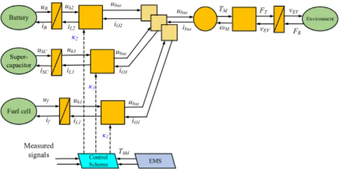
In the studied electric vehicle show in Fig. 6, a

(6)

super-capacitor bank with a bidirectional DC-DC converter and a fuel cell bank with a boost converter are added in parallel on the battery with another bidirectional DC-DC converter. At the DC link, the voltage is imposed by the battery while the currents are distributed in a parallel node. Thus, thecurrent of the hybrid energy system can be calculated as

1 2 2

bus O O O

iiii (24)

where i bus , i O1 , i O2 , and i O3 are the DC link current, the output current of the boost converter, and the output current of the bidirectional DC-DC converters of the battery and the supercapacitor, respectively.

The electro-mechanical conversion of the induction motor is calculated by

M M bus

M M M

T k i

e k  (25)

where T M , e M , k M , and ω M denote the traction torque, electromotive force, and electromechanical constant conversion, and rotation speed of the motor, respectively. The mechanical transmission to a wheel is represented by

Battery

Fuel cell Super- capacitor

Environment u B

i B

u SC i SC

u f i f

u h3 i L3

u h1 i L1 u h2

i L2 u bus

i O2

u bus i O3

u bus i O1

u bus i bus

T M ω M

F T v EV

v EV F R

Control

Scheme EMS

κ 2

κ 3

κ 1 Measured

signals T Md

i O1d ,i O2d ,i O3d

Fig. 7 EMR of the studied electric vehicle.

1 0

1 0

EV w M G

j

T G M w

T EV T EV

v R r

F r T R

j F v

F v

 

   

(26)

where v EV and F T denote the velocity of the electric vehicle and the traction force, respectively, R w and α are the wheel radius and efficiency of the gear box, respectively. Thus, the motion equation of the electric

vehicle is given by the following equation.

T R

EV

EV

F F

d v

dt m

    (27)

where m EV is the total mass of the electric vehicle, ∆ denotes all the nonlinearities in the vehicle dynamics including disturbance and model uncertainties, F R is the resistive force, which is calculated as follows 26)

 wind  2

Rolling resistance force Aerodynamic drag force Uphill resistanceforce

R EV r 0.5 a a EV EV l

Fm gC   C vvm gC

      (28)

where g is gravitational acceleration, C r is the rolling resistance coefficient, C a is the standard aerodynamics, v wind is the wind velocity, C l is the slope rate, ρ a is the air density at 20 Celsius degree.

3. EMR and EMS for the FCHEV.

3.1 EMR of the studied FCHEV

The system is described using EMR with the synoptic shown in Table 1. The EMR of the whole system is depicted in Fig. 7, which comprises energy storage and generation subsystem, parallel coupling subsystem, power train subsystem, and EMS block. The EMR describe the energy exchange between the components in the system and emphasize some system characteristic such as physical causality and interaction principle 26) . The control algorithm scheme is then deduced systematically from the EMR. According to the EMS, the desired currents of the three DC-DC converters are calculated to select the power sources of the system. Then three control signals are derived to send to three switchers of the corresponding converters.

3.2 EMS of the hybrid power sources.

The hybrid electric vehicle is supplied by three power sources, which are fuel cell, battery, and super-capacitor. Since fuel cell has slow dynamics, it can be compensated by faster dynamics from storage devices such as battery and supercapacitor.

Supercapacitor has lower energy density than battery,

however, higher power density, which provide very fast

(7)

Measurement of i bus

i bus > 0

u SC <u SCmax i bus >i O1max

i bus >(i O1max +i O2max )

i O1 =i bus

i O1 =0 i O1 =0 i O1 =0

i O2 =0 i O3 =i bus

i O1 =0 i O2 =i bus

i O3 =0

i O1 =i O1max

i O2 =i bus - i O1max

i O3 =0

i O1 =i O1max

i O2 =i O2max

i O3 =i bus - i O2max -i O3max YES

NO

YES

NO NO YES

NO

YES

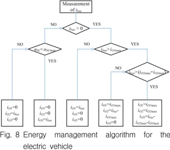
Fig. 8 Energy management algorithm for the electric vehicle

dynamic cycles. In addition, battery lifetime relies on many factors such as the number and depth of discharge cycles, operating temperature, and so on. In order to keep the battery operating in a long lifetime, the battery current slope should be limited. On the contrary, supercapacitor is employed for fast dynamic cycles.

In order to manage the energy distribution between the fuel cell, battery, and super-capacitor based on a dynamic classification, the four following operating modes are considered

(1) Fuel cell, battery and supercapacitor combined driving mode: the main source and storage supply energy to the load. In this mode, the fuel cell system mainly drives the vehicle. If the demand power is greater than maximum power of fuel system, the fuel system supplies the maximum power, and the remaining demand power is provided by the battery if the SOC of the battery, denoted as δ B , higher than its expected value, denoted as SOC*. If the demand power still cannot be satisfied, the supercapacitor must discharge if δ SC is higher than SOC*. The power calculation in this mode can be expressed by the following equation.

max

1 2 3

FC FC

tract FC DC B DC SC DC

P P

P PPP

    

 (29)

where P FC , P B , P SC , P tract , P FCmax denote the power of fuel cell system, battery power, supercapacitor power, traction power, and maximum value of fuel cell power, respectively, η DC1 , η DC2 , η DC3 are the efficiency of the

DC-DC converters for fuel cell system, battery, and supercapacitor, respectively.

(2) Fuel cell and battery combined driving mode: In this mode, if the δ B is higher than SOC*, the battery discharge and the remaining demand power is provided by the fuel cell. If δ SC is lower than SOC*, then it must be charged by the fuel cell. The power relation in this mode is given by

3 1 2

tract SC DC FC DC B DC

PP   P   P  (30)

(3) Fuel cell individual driving mode: In this mode, the fuel cell individually drives the vehicle. If the demand power is lower than maximum value of the fuel cell system, δ B and δ SC are lower than SOC*, then fuel cell must charge the battery and supercapacitor. The power relation equation is derived as

Battery

Fuel cell Super- capacitor

Environment u B

i B

u SC

i SC

u f

i f

u h3

i L3

u h1

i L1

u h2

i L2

u bus

i O2

u bus

i O3

u bus

i O1

u bus

i bus

T M

ω M

F T

v EV

v EV

F R

EMS κ 2

κ 3

κ 1

Driving Cycle v EVd

F Td

i busd

i O2d

i O3d

i O1d

i O1d

u f_mes

i O3d

u SC_mes

i O3d

u SC_mes

Fig. 9 Control architecture for the FCHEV system

2 3 1

tract B DC SC DC FC DC

PP   P   P  (31)

(4) Recovery mode: when the vehicle decelerates or brakes, the motor turns into power generation mode and the fuel cell system stop working. In this mode, the supercapacitor recover energy firstly. When the supercapacitor is full of energy, then the battery recovers energy.

From the above analysis, the EMS for the electric

vehicle can be expressed in the Fig. 8. As depicted in

this figure, the energy distribution between fuel cell and

storage devices relies on the required current and the

voltage of the supercapacitor, where i O1max , i O2max , and

u SCmax are the maximum values of i O1 , i O2 , and u SC ,

respectively.

(8)

3.3 Backstepping sliding mode control method.

The control scheme for the electric vehicle is developed based on the motion equation of the vehicle (27) and the dynamic equations of the converters (21)-(23).

Let us define the tracking error e 1 = v EV –v EVd , where v EVd denotes the desired speed of the electric vehicle.

The sliding surface for the velocity tracking subsystem can be chosen as

1 1 1

s   e   e (32)

Assuming that the resistance force F R can be measured, then from the vehicle dynamics (27), the desired traction force is designed as

 1 1 2 sign( ) 

Td R EV EVd

FFm v    e   k s ks   (33)

where k 1 and k 2 are positive designed parameters.

Consider a Lyapunov function

2

1 0.5 1

V Ls (34)

Taking the derivative of V L1 and defining e 2 = F T -F Td , one obtains

2

1 1 1 1 2 1 1 2 1 1

1

L

EV

V s s s e k s k s s

  m    

  (35)

The parameter k 2 is chosen such that k 2 > sup   .

It is clear that the tracking error e 1 could converge to zero only if the tracking error e 2 is close to zero.

Therefore, the objective of the next step is control e 2

as small as possible.

Let us define i busd is the desired value of the DC link current, e 3 = i bus –i busd is the DC link current tracking error,

Table 1: Parameters of the hybrid power system Par. Value Unit Par. Value Unit

N c 70 - α 0.6 -

R 8.3145 Jmol -1 K -1 r H2 0.99 -

F 96,485 Cmol -1 r O2 0.21 -

z 2 - R B 1.8e -3 Ω

K c 57.6 - C B 6.5 Ah

R i 0.08 Ω C SC1 150 F

Velocity (m /s) V elocity E rror(m /s)

Fig. 10 Velocity tracking performances and tracking errors

then we obtain the following relationship

3 3 2

3 j w G M

e K e K R

r k

 (36)

In order to control the tracking error e 3 converge to zero, according to the equation (24), three DC-DC converter output currents i O1 , i O2 , i O3 should follow their desired values i O1d , i O2d , i O3d . Therefore, inversed control signals κ 1 , κ 2 , κ 3 are derived for the three converters as the following.

 

1 K e p 1 O 1 K i 1 e dt u O 1 f mes _ / u bus mes _

     (37)

 

2 K e p 2 O 2 K i 2 e dt u O 2 B mes _ / u bus mes _

     (38)

 

3 K e p 3 O 3 K i 3 e dt u O 3 SC mes _ / u bus mes _

     (39)

where e O1 = i O1 -i O1d , e O2 = i O2 -i O2d , e O3 = i O3 -i O3d , K p1 , K p2 , K p3 , K i1 , K i2 , K i3 are designed control parameters, u B_mes , u SC_mes , u f_mes , and u bus_mes are the measurement values of u B , u SC , u f , and u bus .

4. Simulation results and discussion

In order to validate the effectiveness of the proposed

control method for the fuel cell hybrid electric vehicle,

some simulation tests have been done. The simulation

tests are performed in MATLAB/Simulink environment.

(9)

0 300 600 900 1200 1500 1800 0

20

40 Reference Current Response

0 300 600 900 1200 1500 1800

-20 0 20

0 300 600 900 1200 1500 1800

Time(s) -50

0 50

Fig. 11 Current tracking performances

Current tracking error(A)

Fig. 12 Current tracking errors

The sampling time of the simulation test is selected as T s = 10 -4 second. The parameters of the hybrid fuel cell, battery, and supercapacitor is depicted in the Table 1.

The control structure for the FCHEV system is show in Fig. 9. Firstly, from the standard cycle condition for testing vehicle performance, the reference velocities are given. Then the velocity controller block will calculate the desired traction force for the powertrain system to guarantee the tracking performance of the car speed.

Basing on electromechanical conversion and the desired traction force, the desired bus current is computed, which is the input of the energy management block along with supercapacitor voltage. The inversed control schemes for the three DC-DC converters are then developed to derive the suitable control signals κ 1 , κ 2 , and κ 3 . In this paper, the Worldwide Harmonized Light Vehicle Test Procedure (WLTP) are chosen to be the standard driving cycle for the FCHEV system. The parameters of the proposed control approach are chosen

as λ=0.1, k 1 = 2.5, k 2 =1.6. The control performance of the proposed control method is compared to the PID controller to investigate the effectiveness of the proposed control method. The parameters are optimized as K p = 5.5, K d =0.5 , and K i =16 using trial and error method.

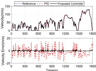
Applying the comparative controllers, the velocity tracking performances of the vehicle, the velocity tracking errors, the current tracking errors, and the SOC of the battery and the supercapacitor are shown in Figs.

10-13, respectively.

Fig. 13 SOCs of the battery and the supercapacitor.

As can be seen in Fig. 10, the simulation results show that both controllers can achieve good tracking performances, however, the proposed control method overperforms the PID controller, exhibiting better trajectory tracking performances. In addition, the current tracking performance shown in Fig. 11 and Fig. 12 reveal that effectiveness of the inversed current tracking control, which guarantee the fast response and high tracking performance of three output currents of the three DC-DC converters. The SOCs of the battery and supercapacitor are also measured during the WLTP driving cycle. As can be seen in Fig. 13, the state of charge of the battery is significantly lower than that of the super-capacitor. This result indicates that the lifetime of the battery can be guaranteed, and the maintenance cost can be reduced.

5. Conclusion

In this paper, the backstepping sliding mode based

inversed control algorithm for the fuel cell hybrid

electric vehicle is proposed. A detail model of all the

(10)

components and the control algorithm are developed in EMR. In addition, the EMS is derived to calculate the reference powers for the fuel cell system, the battery, and the super-capacitor. Finally, the simulation results with WLTP standard driving cycle validate the effectiveness of the EMS and the proposed control algorithm with not only high tracking performance for the car speed and currents but also assuring the long lifetime of the battery. One of our future work is to implement the proposed control algorithm in the real system to validate the control performance of the designed control system in presence of noises, uncertainties and state of health degradation.

Acknowledgement

This work was supported by Basic Science Research Program through the National Research Foundation of Korea (NRF) funded by the Korean government (MEST) (NRF-2017R1A2B3004625).

References

1) M. Zandi et al., "Energy Management of a Fuel Cell/Supercapacitor/Battery Power Source for Electric Vehicular Applications", IEEE Transactions on Vehicular Technology, Vol.60, No.2, pp.433-443, 2011.

2) P. Thounthong, S. Raël and B. Davat, "Energy management of fuel cell/battery/supercapacitor hybrid power source for vehicle applications", Journal of Power Sources, Vol.193, No.1, pp.376-385, 2009.

3) T. D. Dang et al., "Design, Modeling and Analysis of a PEM Fuel Cell Excavator with Supercapacitor/

Battery Hybrid Power Source", Journal of Drive and Control, Vol.16, No.1, pp.45-53, 2019.

4) K. Ettihir et al., "Design of an adaptive EMS for fuel cell vehicles", International Journal of Hydrogen Energy, Vol.42, No.2, pp.1481-1489, 2017.

5) Y.-X. Yu and K. K. Ahn, "Optimization of energy regeneration of hybrid hydraulic excavator boom system", Energy Conversion and Management, Vol.183, pp.26-34, 2019.

6) J. S. Joh, "A Review on New Non-hybrid Technologies to Improve Energy Efficiency of Construction Machineries", Journal of Drive and Control, Vol.13, No.3, pp.53-66, 2016.

7) Y. X. Yu, E. J. Jeong and K. K. Ahn, "Review of Energy Saving Technology of Hybrid Construction Machine", Journal of Drive and Control, Vol.15, No.4, pp.91-100, 2018.

8) J. Y. Huh, "Energy Saving in Boom Motion of Excavators using IMV", Journal of Drive and Control, Vol.14, No.3, pp.1-7, 2017.

9) L. Boulon et al., "From Modeling to Control of a PEM Fuel Cell Using Energetic Macroscopic Representation", IEEE Transactions on Industrial Electronics, Vol.57, No.6, pp.1882-1891, 2010.

10) A. Bouscayrol et al., "Energetic Macroscopic Representation and Inversion-Based Control Illustrated on a Wind-Energy-Conversion System Using Hardware-in-the-Loop Simulation", IEEE Transactions on Industrial Electronics, Vol.56, No.12, pp.4826-4835, 2009.

11) G. L. Lopez et al., "Hybrid PEMFC-supercapacitor system: Modeling and energy management in energetic macroscopic representation", Applied Energy, Vol.205, pp.1478-1494, 2017.

12) M. R. Barakat et al., "Energetic Macroscopic Representation of a Marine Current Turbine System with Loss Minimization Control", IEEE Transactions on Sustainable Energy, Vol.9, No.1, pp.106-117, 2018.

13) S. N. Motapon, O. Tremblay and L.-A. Dessaint,

"Development of a generic fuel cell model:

application to a fuel cell vehicle simulation", International Journal of Power Electronics, Vol.4, No.6, pp.505-522, 2012.

14) R. C. Kroeze and P. T. Krein, "Electrical battery model for use in dynamic electric vehicle simulations", Proceedings of 2008 IEEE Power Electronics Specialists Conference, pp.1336-1342, Rhodes, Greece, 2008.

15) R. Xiong et al., "Modeling for Lithium-Ion Battery used in Electric Vehicles", Procedia Engineering, Vol.15, pp.2869-2874, 2011.

16) H. He, R. Xiong and J. Fan, "Evaluation of

(11)

Lithium-Ion Battery Equivalent Circuit Models for State of Charge Estimation by an Experimental Approach", Energies, Vol.4, No.4, 2011.

17) X. Hu, S. Li and H. Peng, "A comparative study of equivalent circuit models for Li-ion batteries", Journal of Power Sources, Vol.198, pp.359-367, 2012.

18) H. He et al., "Comparison study on the battery models used for the energy management of batteries in electric vehicles", Energy Conversion and Management, Vol.64, pp.113-121, 2012.

19) J. H. Chang, F. P. Dawson and K. Lian, "A first principles approach to develop a dynamic model of electrochemical capacitors", Proceedings of The 2010 International Power Electronics Conference - ECCE ASIA-, pp.2382-2389, Sapporo, Japan, 2010.

20) B. K. Kim et al., Electrochemical Supercapacitors for Energy Storage and Conversion, Handbook of Clean Energy Systems, John Wiley & Sons, Ltd., New York, pp. 2015.

21) L. Zhang et al., "A review of supercapacitor modeling, estimation, and applications: A control/

management perspective", Renewable and Sustainable Energy Reviews, Vol.81, Pt. 2, pp.1868-1878, 2018.

22) S.-H. Kim et al., "Advanced Dynamic Simulation of Supercapacitors Considering Parameter Variation and Self-Discharge", IEEE Transactions on Power Electronics, Vol.26, No.11, pp.3377-3385, 2011.

23) P. Saha, S. Dey and M. Khanra, "Modeling and State-of-Charge Estimation of Supercapacitor Considering Leakage Effect", IEEE Transactions on Industrial Electronics, pp.1-1, 2019.

24) A. Castaings et al., "Practical control schemes of a battery/supercapacitor system for electric vehicle", IET Electrical Systems in Transportation, Vol.6, No.1, pp.20-26, 2016.

25) L. Gauchia et al., "Fuel cell, battery and supercapacitor hybrid system for electric vehicle:

Modeling and control via energetic macroscopic representation", Proceedings of 2011 IEEE Vehicle Power and Propulsion Conference, Chicago, IL, USA, 2011.

26) M. J. Blondin et al.,"Metaheuristic Optimization for

Backstepping Control and Inversion Based Control

from EMR for an Electric Vehicle", Proceedings of

2018 IEEE Vehicle Power and Propulsion

Conference (VPPC), Chicago, IL, USA, 2018.

수치

Fig.  1  Fuel  cell  hybrid  electric  vehicle  configuration
Fig.  5  Equivalent  circuit  model  of  DC-DC  converter.
Fig.  7  EMR  of  the  studied  electric  vehicle.
Fig. 8 Energy  management  algorithm  for  the  electric  vehicle
+3

참조

관련 문서

The construction of Electric motor propulsion system are presumed arrangement of boat and compared The engine fuel of cost with battery charge of cost .The Model

If this spring should happen to be part of a larger elastic system, it will always contribute the energy (2.3) to the total stored energy of the system

In this paper, we developed a data management system for shipboard machinery equipment and the monitoring application for the verification of the utility, and we

Regional Innovation Center for the Hydrogen Fuel-Cell and Solar

Basic construction of axial-lead tubular plastic-film dielectric capacitors Floyd 책 383쪽 그림 9.12. Polyester-film capacitors: (a) axial lead; (b) radial lead (Courtesy

The change in the internal energy of a closed thermodynamic system is equal to the sum em is equal to the sum of the amount of heat energy supplied to the system and the work.

The change in the internal energy of a closed thermodynamic system is equal to the sum em is equal to the sum of the amount of heat energy supplied to the system and the work.

This study focuses on the energy-related legal system of Australia and examines (1) the general regulatory framework of energy industries, (2) the management and oversight