경북대학교 치의학전문대학원, 1치주과학교실, 2구강생화학교실, 3구강악안면방사선학교실 김용건1∙이영균2∙안서영3
이 연구의 목적은 환자의 머리 위치에 따른 파노라마방사선사진의 수평 및 수직 확대율을 비교 평가하는 것 이었다. 직경 4 mm인 금속구를 건조 두개골의 하악 전치부와 우측 대구치부의 치조골 상방에 위치시켰다. 수평 및 수직적 위치의 변화를 재현하기 위해 수직, 수평 이동량을 조절할 수 있는 두개골 고정장치를 이용하여, 전 방, 후방, 좌측 및 우측으로 이동시킨 후 파노라마방사선사진을 OP-100D를 이용하여 획득하였다. 촬영된 영상 은 DICOM 형식으로 저장되었고, INFINITT PACS software를 이용하여 금속구의 폭과 높이의 평균값을 구하였 다. 적절한 위치에서 촬영된 파노라마방사선사진에서 금속구의 수평 확대율은 1.224 - 1.439였고, 수직 확대율은 1.286 - 1.345였다. 건조 두개골의 위치 변화에 따른 수평 확대율은 0.798 - 6.297로 통계적으로 유의한 차이를 보 인 반면(P<0.05), 수직 확대율은 1.245 - 1.418 정도로 수평 확대율에 비해 차이를 보이지 않았다. (구강회복응용 과학지 2013:29(3):249 - 258)
주요어: 수직 확대율, 수평 확대율, 파노라마방사선사진
교신저자: 안서영
경북대학교 치의학전문대학원 구강악안면방사선학교실 대구광역시 중구 달구벌대로 2177번지, 700-412, 대한민국
Tel: +82-53-600-7423, Fax: +82-53-425-6025, E-mail: [email protected]
원고접수일: 2013년 6월 21일, 원고수정일: 2013년 8월 3일, 원고채택일: 2013년 9월 25일
서 론
무치악 부위의 치료방법으로 임플란트 매식술 은 보편화되었으며, 임플란트 식립 부위 잔존치 조골의 평가에 파노라마방사선사진이 주로 이 용된다.1)CBCT (Cone-beam Computed Tomography) 나 CT (Computed Tomography)는 방사선사진상의
변형이나 왜곡이 적고, 2차원적 영상에서 얻을 수 없는 단면상을 통해 해부학적 구조물을 협설 방향으로 중첩이 없이 관찰할 수 있어 임플란트 매식술을 시행할 때 추천되나2)모든 수술 환자에 게 적용하기에는 비용이나 효율적인 측면에서 제한이 있다. 따라서 일반적인 경우에는 파노라 마방사선사진을 바탕으로 임플란트 식립을 계
획하게 된다.3,4)파노라마방사선사진은 촬영 시간 이 짧고, 촬영이 간단하며 한 장의 사진으로 상, 하악골을 포함한 넓은 부위를 평가할 수 있고, 상 대적으로 방사선 노출량이 적은 장점이 있어 임 상에서 매우 유용하다. 또한 임상가가 임플란트 의 수술적 위치 설정을 정하는데 많은 도움을 주 며, 특히 하악 구치부 임플란트 매식술을 위해 잔 존골을 평가할 때 비교적 안전한 방법으로 여겨 져 왔다.5-17)하지만 파노라마방사선사진은 촬영 원리와 장비가 자체적으로 가지고 있는 투사의 기하학적 원리, 상층의 모양, 수평 및 수직적 확 대 요소 간의 차이뿐만 아니라 촬영 시 환자 위치 의 오류 등으로 인하여 영상이 다양한 정도로 왜 곡될 수 있으며 이로 인하여 피사체의 크기 및 형 태의 측정에 오류가 나타날 수 있어 임플란트 매 식술의 계획시 이 점이 충분히 고려되어야 한
다.1,4,18-22)Schiff23)는 무작위로 고른 1000명의 파노라
마방사선사진 중 20.3% 만이 환자 위치에 관한 실수나 기술적인 실수가 없이 촬영 되었으며, 오 류가 있는 사진 중 환자의 머리 위치에 관한 실수 (98.1%)가 다른 기술적인 실수(17.8%) 보다 많다 고 하였다. 일반적으로 임플란트 식립 부위의 잔 존 치조골 양의 평가는 금속구를 포함한 스텐트 를 제작하고, 이를 구강 내에 장착한 상태로 파노 라마방사선사진을 촬영하여 평가하게 된다.19)
이 연구의 목적은 건조 두개골, 직경을 알고 있 는 금속구 및 수직, 수평 이동량을 정확히 조절할 수 있는 두개골 고정장치를 이용하여, 촬영 시 환 자의 머리 위치가 전방, 후방, 좌측, 그리고 우측 으로 이동함에 따른 파노라마방사선사진의 수 평 및 수직 확대율을 평가하는 것이었다.
연구 재료 및 방법
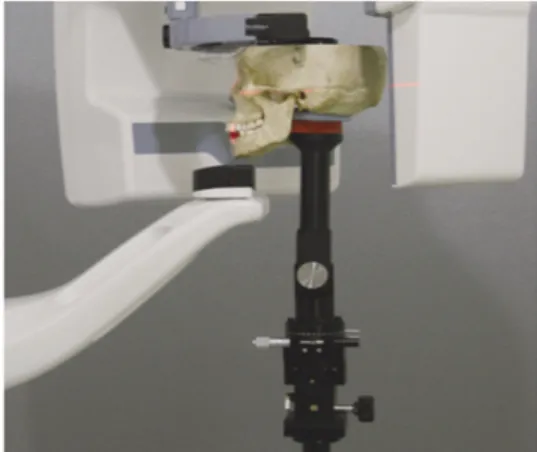
악골의 비대칭 및 기형이 없는 건조 두개골을 특별히 고안된 두개골 고정장치에 고정하였다 (Fig. 1). 건조 두개골의 하악 전치부(2개)와 우측 대구치부(3개)에 4 mm인 금속구를 유틸리티 왁 스로 고정하여 방사선사진 촬영 및 수술에서 사
용되는 스텐트로 사용하였다. 수평이동량을 정 확히 조절할 수 있는 두개골 고정장치는 전후 및 좌우 15 mm까지 수평이동이 가능하고, 수평면을 기준으로 상하로 30�, 시상면을 기준으로 좌우로 15�의 회전이 가능하게 제작되었다. 파노라마방 사선사진은 OP-100D (Instrumentarium Imaging Co., Tuusula, Finland)를 이용하여 관전압 60 kVp, 관전 류 2 mA, 노출시간 17.6초로 촬영하였다. 기준으 로 사용될 파노라마방사선사진 촬영은 파노라 마 장비 교합제에 상, 하악 전치의 절단연을 위치 시키고, 세 개의 지시광을 정중 시상면, 프랑크푸 르트선 및 상악 견치의 치축에 맞추었으며, 금속 구를 상층에 위치시켰다. 파노라마방사선사진 을 촬영 한 후, 두개골 고정장치를 이용하여 전 방, 후방, 좌측 및 우측으로 3 mm 간격, 즉 3, 6, 9, 12, 15 mm에서 파노라마방사선사진을 촬영하여 총 20매의 방사선사진을 획득하였다. 촬영된 영 상은 DICOM (Digital imaging and Communication in Medicine)형식으로 저장되었고, INFINITT PACS software (Infinitt Co., Ltd., Seoul, Korea)를 이용하여 3백만 화소의 판독용 모니터 ME311L (Totoku Electric Co., Ltd., Tokyo, Japan)에서 계측 금속구의
Fig. 1. Mounted skull in the dental panoramic X-ray machine.
폭과 높이 한 명의 관찰자가 일주일 간격으로 3 회 반복 측정하여 평균값을 구하였다.
확대율의 정의
수평 확대율 = 파노라마방사선 사진에서 금속구의 폭
실제 금속구의 직경
수직 확대율 = 파노라마방사선사진에서금속구의높이
실제 금속구의 직경
통계분석
데이터 분석은 PASW 19 (SPSS, Chicago, IL, USA)을 이용하였고, Kruskal-Wallis test, Mann- Whitney test로 분석하였다. 분석결과 얻어진 유의
확률 값이 0.05이하 일 경우 통계적으로 유의하 다고 평가하였다. 유의한 차이가 있는 경우 Tukey test를 이용하여 사후 검정하였다.
결 과
기준 위치 및 전방, 후방, 좌측, 우측 이동량에 따른 금속구의 수평 확대율 및 수직 확대율을 Table I, II에 정리하였으며, 각각의 조건에서 획득 한 파노라마방사선사진은 Fig. 2에 나타내었다.
좌측에서부터 우측으로 금속구의 위치를 편의 상 치아의 위치에 준하여 #32, 42, 46, 47, 48로 구 분하였다.
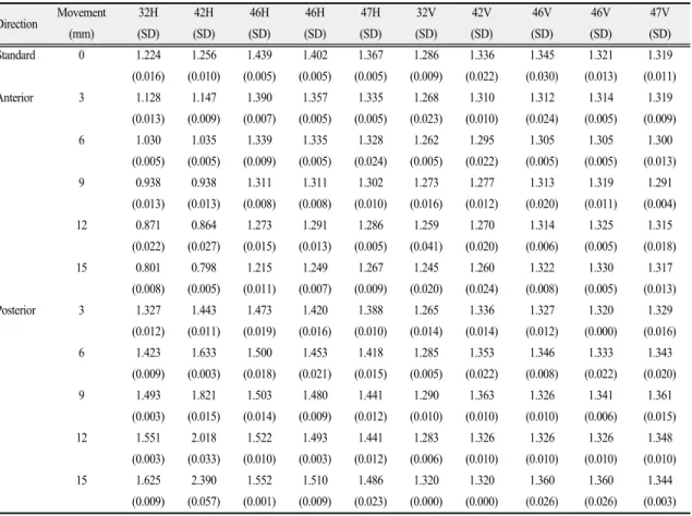
Table Ⅰ. Horizontal and vertical magnification: anterior and posterior movements
Direction Movement 32H 42H 46H 46H 47H 32V 42V 46V 46V 47V (mm) (SD)(SD)(SD)(SD)(SD)(SD)(SD) (SD) (SD) (SD) Standard 0 1.224 1.256 1.439 1.402 1.367 1.286 1.336 1.345 1.321 1.319
(0.016)(0.010)(0.005)(0.005)(0.005)(0.009)(0.022) (0.030) (0.013) (0.011) Anterior 3 1.128 1.147 1.390 1.357 1.335 1.268 1.310 1.312 1.314 1.319
(0.013)(0.009)(0.007)(0.005)(0.005)(0.023)(0.010) (0.024) (0.005) (0.009) 6 1.030 1.035 1.339 1.335 1.328 1.262 1.295 1.305 1.305 1.300
(0.005)(0.005)(0.009)(0.005)(0.024)(0.005)(0.022) (0.005) (0.005) (0.013) 9 0.938 0.938 1.311 1.311 1.302 1.273 1.277 1.313 1.319 1.291
(0.013)(0.013)(0.008)(0.008)(0.010)(0.016)(0.012) (0.020) (0.011) (0.004) 12 0.871 0.864 1.273 1.291 1.286 1.259 1.270 1.314 1.325 1.315
(0.022)(0.027)(0.015)(0.013)(0.005)(0.041)(0.020) (0.006) (0.005) (0.018) 15 0.801 0.798 1.215 1.249 1.267 1.245 1.260 1.322 1.330 1.317
(0.008)(0.005)(0.011)(0.007)(0.009)(0.020)(0.024) (0.008) (0.005) (0.013) Posterior 3 1.327 1.443 1.473 1.420 1.388 1.265 1.336 1.327 1.320 1.329
(0.012)(0.011)(0.019)(0.016)(0.010)(0.014)(0.014) (0.012) (0.000) (0.016) 6 1.423 1.633 1.500 1.453 1.418 1.285 1.353 1.346 1.333 1.343
(0.009)(0.003)(0.018)(0.021)(0.015)(0.005)(0.022) (0.008) (0.022) (0.020) 9 1.493 1.821 1.503 1.480 1.441 1.290 1.363 1.326 1.341 1.361
(0.003)(0.015)(0.014)(0.009)(0.012)(0.010)(0.010) (0.010) (0.006) (0.015) 12 1.551 2.018 1.522 1.493 1.441 1.283 1.326 1.326 1.326 1.348
(0.003)(0.033)(0.010)(0.003)(0.012)(0.006)(0.010) (0.010) (0.010) (0.010) 15 1.625 2.390 1.552 1.510 1.486 1.320 1.320 1.360 1.360 1.344
(0.009)(0.057)(0.001)(0.009)(0.023)(0.000)(0.000) (0.026) (0.026) (0.003) H: horizontal magnification, V: vertical magnification, SD: standard deviation
기준 위치에서 금속구의 수평 확대율은 위치 에 따라 1.224 - 1.439였고, 수직 확대율은 1.286 - 1.345였다. 건조 두개골의 위치 변화에 따른 수평 확대율은 0.798 - 6.297 정도로 큰 차이를 보인 반 면, 수직 확대율은 1.245 - 1.418 정도로 수평 확대 율에 비해 큰 차이를 나타내지 않았다(Table I, II
& Fig. 3).
전방 이동에서는 피사체와 센서의 거리가 가 까워짐에 따라 수평 및 수직 확대율이 모두 감소 되었다. 수평 확대율의 변화량은 이동량에 따라 전치부에서 -0.459 - -0.096, 구치부에서 -0.22 - -0.032로 전치부에서 더 많이 감소하였다. 수직 확대율의 변화량은 이동량에 따라 전치부에서
-0.076 - -0.014, 구치부에서는 -0.040 - -0.002로 전 치부에서 더 많이 감소하였으나, 수평 확대율에 비해 그 변화의 정도가 미미하였다.
후방 이동에서는 피사체와 센서의 거리가 멀 어짐에 따라 수평, 수직 확대율이 전반적으로 증 가하였다. 수평 확대율의 변화량은 이동량에 따 라 전치부에서 0.103 - 1.134, 구치부에서 0.018 - 0.119 증가하여 전치부에서 더 많이 증가하였다.
수직 확대율의 변화량은 이동량에 따라 전치부에 서 -0.021 - 0.03, 구치부에서 -0.019 - 0.042로 전치부, 구치부 모두에서 그 변화의 정도가 미미하였다.
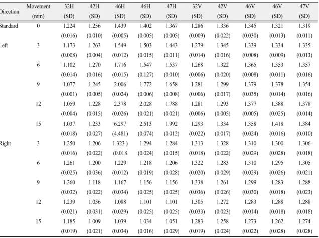
좌측 이동에서는 피사체와 센서의 거리가 가 까워지는 좌측 금속구의 확대율은 감소하였고,
Table Ⅱ. Horizontal and vertical magnification: left and right movements
Direction Movement 32H 42H 46H 46H 47H 32V 42V 46V 46V 47V
(mm) (SD)(SD)(SD)(SD)(SD)(SD)(SD) (SD) (SD) (SD) Standard 0 1.224 1.256 1.439 1.402 1.367 1.286 1.336 1.345 1.321 1.319
(0.016)(0.010)(0.005)(0.005)(0.005)(0.009)(0.022) (0.030) (0.013) (0.011) Left 3 1.173 1.263 1.549 1.503 1.443 1.279 1.345 1.339 1.334 1.335
(0.008)(0.004)(0.012)(0.015)(0.011)(0.014)(0.016) (0.008) (0.009) (0.013) 6 1.102 1.270 1.716 1.547 1.537 1.268 1.322 1.365 1.353 1.357
(0.014)(0.016)(0.015)(0.127)(0.010)(0.006)(0.020) (0.008) (0.011) (0.016) 9 1.077 1.245 2.006 1.772 1.658 1.281 1.299 1.379 1.378 1.354
(0.001)(0.005)(0.024)(0.006)(0.008)(0.006)(0.017) (0.035) (0.014) (0.016) 12 1.059 1.228 2.378 2.028 1.788 1.281 1.293 1.377 1.388 1.378
(0.004)(0.015)(0.026)(0.021)(0.021)(0.006)(0.005) (0.005) (0.025) (0.014) 15 1.037 1.233 6.297 2.513 1.992 1.293 1.334 1.358 1.418 1.384
(0.018)(0.027)(4.481)(0.074)(0.012)(0.022)(0.017) (0.024) (0.016) (0.010) Right 3 1.250 1.206 1.323 )1.294 1.284 1.313 1.328 1.310 1.300 1.306
(0.016)(0.022) (0.018 (0.024)(0.015)(0.018)(0.022) (0.029) (0.028) (0.018) 6 1.261 1.200 1.229 1.218 1.206 1.322 1.283 1.310 1.295 1.305
(0.025)(0.036)(0.012)(0.019)(0.028)(0.020)(0.029) (0.029) (0.026) (0.021) 9 1.260 1.118 1.167 1.156 1.156 1.338 1.261 1.299 1.283 1.288
(0.032)(0.022)(0.034)(0.025)(0.025)(0.036)(0.026) (0.030) (0.018) (0.023) 12 1.239 1.056 1.088 1.101 1.101 1.305 1.272 1.283 1.288 1.288
(0.021)(0.031)(0.029)(0.025)(0.025)(0.033)(0.023) (0.014) (0.018) (0.018) 15 1.185 1.009 1.039 1.034 1.051 1.283 1.258 1.273 1.262 1.274
(0.019)(0.021)(0.034)(0.016)(0.029)(0.019)(0.024) (0.022) (0.028) (0.028) H: horizontal magnification, V: vertical magnification, SD: standard deviation
피사체와 센서의 거리가 멀어지는 우측 금속구 의 확대율은 전반적으로 증가하였다. 수평 확대 율의 변화량은 이동량에 따라 전치부에서는 -0.187 - 0.014로 미미하였다. 구치부에서는 수평 확대율의 변화량이 0.076 - 4.858로 아주 컸으며, 특히 #46번 부위 금속구의 확대율이 가장 컸다.
수직 확대율의 변화량은 전치부에서 -0.044 - 0.009, 구치부에서 -0.006 - 0.096로 미미하였다.
우측 이동에서는 피사체와 센서의 거리가 멀 어지는 좌측 금속구의 확대율은 증가하였고, 피 사체와 센서의 거리가 가까워지는 우측 금속구 의 확대율은 감소하였다. 수평 확대율의 변화량 은 이동량에 따라 전치부에서 -0.247 - 0.037로 미 미하였다. 구치부에서는 수평 확대율의 변화량 이 -0.400 - -0.083로 좌측 이동에 비해 폭이 크지 않았다. 수직 확대율의 변화량은 전치부에서
-0.079 - 0.052, 구치부에서는 -0.072 - -0.013로 미미 하였다.
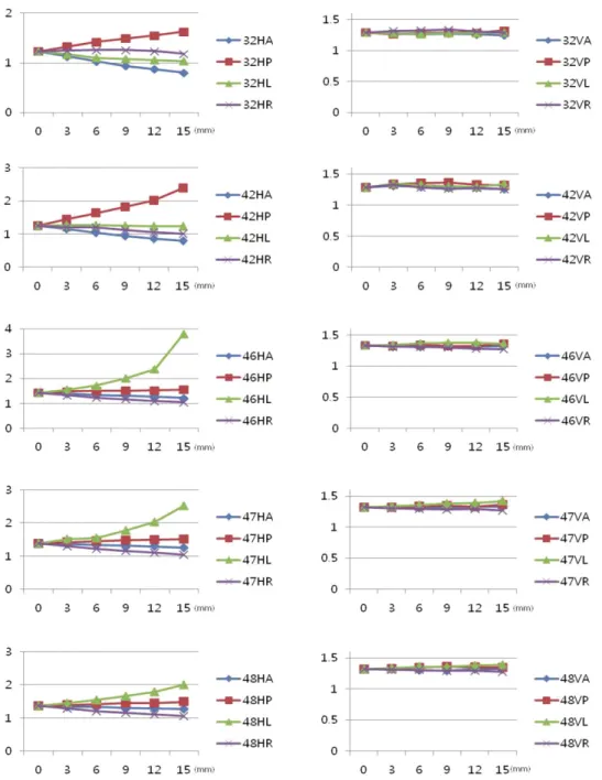
전후방 이동에서는 상층이 좁고 이동의 축에 가까운 전치부의 확대율이 크게 변하였고, 좌우 이동에서는 전치부보다는 구치부의 확대율 변 화가 컸다(Fig. 3).
각 치아부위별로 분석해보면 #32부위는 기준 위치와 비교시 수평 확대율은 모든 구간에서 통 계적으로 유의한 차이가 있었다(P<0.05). 수직 확 대율은 후방이동을 제외하고는 통계적으로 유 의한 차이는 없었다. #42부위의 수평 확대율은 통계적으로 유의한 차이가 있었다(P<0.05). #46 부위의 수평 확대율은 모든 구간에서 통계적으 로 유의한 차이가 있었지만(P<0.05) 수직 확대율 은 통계적으로 유의한 차이가 없었다. #47, 48부 위는 수평 확대율은 모든 구간에서 통계적으로 Fig. 2. Panoramic image according to the anterior, posterior, left and the right movements.
Fig. 3. Horizontal and vertical magnification according to the location (HA; horizontal magnification of the anterior movement, HP; horizontal magnification of the posterior movement, HL; horizontal magnification of the left movement, HR; horizontal magnification of the right movement, VA; vertical magnification of the anterior movement, VP; vertical magnification of the posterior movement, VL;
vertical magnification of the left movement, VR; vertical magnification of the right movement).
유의한 차이가 있었고(P<0.05), 수직 확대율은 좌 측이동을 제외하고는 통계적으로 유의한 차이 는 없었다.
고 찰
이 연구의 목적은 환자의 머리가 적절한 위치 에서 촬영된 파노라마방사선사진과 비교하여, 전방, 후방, 좌측, 우측으로 수평 이동함에 따라 이동량에 따른 파노라마방사선사진의 부위별 수평 및 수직 확대율의 변화를 관찰하는 것이었 다. 파노라마방사선사진촬영은 일종의 단층촬 영이므로 촬영하고자 하는 부위를 상층에 정확 히 위치시켜야 한다. 따라서 검사하고자 하는 치 아와 악골이 상층에서 벗어나게 되면 심하게 축 소되거나 확대된 상을 얻게 되며 이를 근거로 골 량을 측정하면 심각한 오류를 낳을 수 있다.24,25) 대부분의 파노라마방사선사진 촬영기는 환자를 적절히 위치시키기 위해 지시광을 사용하지만 임상가는 촬영기의 실제 상층의 위치를 파악할 수 없다. 파노라마촬영기의 X선 관구와 디지털 센서 혹은 필름 수용기의 이동 속도 및 회전 중심 의 개수와 같은 여러 가지 설계 특성은 기종마다 다양하다. 같은 기종의 모델에서도 사용에 따른 이동 구성 요소의 마모로 인해 상층의 위치에 약 간의 변형이 야기될 수 있다.4)파노라마방사선사 진의 가장 중요한 오차는 환자의 위치에 의해 발 생한다.23)적절한 위치에서 촬영된 파노라마방사 선사진의 수평 확대율은 1.15 - 1.35, 수직 확대율 은 1.2 - 1.30으로 보고되었다.16,26)또한 확대율은 환자 개개인의 악궁의 크기와 모양에 영향을 받 으며16)악궁의 curve로 인하여 확대율은 견치와 소구치 부위에서 최대이고, 제 3대구치 부위에서 최소일 수 있다.27)이번 연구에서 표준 위치에서 의 파노라마방사선사진의 수평 확대율은 금속 구의 위치 따라 1.224 - 1.439, 수직 확대율은 1.286 - 1.345로 조금 크게 나타났다. 이는 건조 두개골 의 크기가 정상 성인의 두개골 크기보다 작아 부 위별로 금속구와 센서 사이의 거리가 달라서 인
것으로 생각되며, 소구치에 가까운 #46 부위의 금속구 확대율이 가장 컸다.
전형적인 파노라마방사선사진에서 상층의 두 께는 전치부보다 구치부가 더 두꺼우며 상층의 중심에서 영상의 흐림과 왜곡이 최소이다.28-30)환 자의 악궁을 상층에 제대로 위치시키지 못하면 수직 수평 확대율의 변화가 나타나며, 수직 확대 율은 상층에서 멀어질수록 미미한데 반해 수평 확대율의 변화는 크다.18,25,31-33)이번 연구에서도 수 평 확대율의 변화가 수직 확대율의 변화에 비해 크게 나타났으며, 전후방 이동에서는 전치부가, 좌우측 이동에서는 구치부가 더 큰 확대율의 변 화를 보였다. 정중 시상면에서 좌우로의 이동은 상, 하악골의 계측에 큰 영향을 미치지 않는다고 알려져 있다.18,31)하지만 이번 연구에서는 수평 확 대율의 경우 좌우측 이동에서 변화를 보였으며, 금속구와 센서의 위치가 멀어지는 경우의 확대 율 증가 폭이 금속구가 센서와 가까워지는 경우 의 확대율 감소 폭에 비해 컸다.
파노라마방사선사진 촬영에서 환자의 머리를 적절히 위치시키지 못하면 부위별로 다양한 확 대율의 변화를 가져오며, 일반적인 확대율을 동 일하게 적용한다면, 파노라마방사선사진에서 예측한 골량과 실제 골량이 차이가 있을 것이다.
이번 연구에서는 파노라마촬영기의 기종에 따 른 영향은 평가되지 않았다. 기종 간 상층의 형태 가 다양하여 확대율의 차이가 있을 것으로 생각 된다. 따라서 이번 연구에서 보고된 확대는 다른 기종에 일반화시키기에는 한계가 있다. 또한 파 노라마방사선사진에서 상의 확대는 환자의 악 골 크기 및 모양에도 영향을 받을 것이다.
결 론
파노라마방사선사진 촬영에서 환자의 전방, 후방, 좌측, 우측 이동에 따른 확대율의 변화는 해부학적인 위치에 따라 다양하였으며, 수평 확 대율의 변화가 크고, 그에 비해 수직 확대율의 변 화는 작았다. 파노라마방사선사진을 이용한 선
형 계측을 위해서는 파노라마방사선사진 촬영 시 환자 머리의 적절한 위치가 중요하며 부위별 확대율을 보다 정확히 예측하기 위해서는 확대 율 보정을 위한 금속구와 같은 기준 물체를 포함 시켜 촬영하는 것이 필요하다.
REFERENCES
1. Xie Q, Soikkonen K, Wolf J, Mattila K, Gong M, Ainamo A. Effect of head positioning in panoramic radiography on vertical measurements: an in vitro study. Dentomaxillofac Radiol 1996;25:61-66.
2. Tal H, Moses O. A comparison of panoramic radiography with computed tomography in the planning of implant surgery. Dentomaxillofac Radiol 1991;20:40-42.
3. Sakakura CE, Morais JA, Loffredo LC, Scaf G. A survey of radiographic prescription in dental implant assessment. Dentomaxillofac Radiol 2003;32:397- 400.
4. Devlin H, Yuan J. Object position and image magnification in dental panoramic radiography: a theoretical analysis. Dentomaxillofac Radiol 2013;
42:29951683.
5. Bushong SC, Glaze SA, Foster JK, Copley RL, Miller JT. Panoramic dental radiography for mass screening? Health Phys 1973;25:489-494.
6. Updegrave WJ. The role of panoramic radiography in diagnosis. Oral Surg Oral Med Oral Pathol 1966;
22:49-57.
7. Keith DA. The detection of abnormalities in the jaws. A survey. Br Dent J 1973;134:129-135.
8. Advantages and disadvantages of the use of dental tomographic radiography. Council on Dental Materials and Devices. J Am Dent Assoc 1977;
94:147.
9. Wall BF, Fisher ES, Paynter R, Hudson A, Bird PD.
Doses to patients from pantomographic and conventional dental radiography. Br J Radiol 1979;
52:727-734.
10. Wical KE, Swoope CC. Studies of residual ridge resorption. I. Use of panoramic radiographs for
evaluation and classification of mandibular resorption. J Prosthet Dent 1974;32:7-12.
11. Landesman HM, Davis WH, Martinoff J, Kaminishi R. Resorption of the edentulous mandible after a vestibuloplasty with skin grafting. J Prosthet Dent 1983;49:619-622.
12. van Waas MA. Ridge resorption in denture wearers after vestibuloplasty and lowering of the floor of the mouth, measured on panoramic radiographs.
Dentomaxillofac Radiol 1983;12:115-121.
13. Goldberg AF, Gergans GA, Mattson DE, Rudman D. Radiographic alveolar process/mandibular height ratio as a predictor of osteoporosis. Gerodontics 1988;4:229-231.
14. Packota GV, Hoover JN, Neufeld BD. A study of the height of intact alveolar bone on panoramic radiographs of adult patients. J Prosthet Dent 1988;
60:504-509.
15. Humphries S, Devlin H, Worthington H. A radio- graphic investigation into bone resorption of mandibular alveolar bone in elderly edentulous adults. J Dent 1989;17:94-96.
16. Choi YG, Kim YK, Eckert SE, Shim CH. Cross- sectional study of the factors that influence radiographic magnification of implant diameter and length. Int J Oral Maxillofac Implants 2004;19:594- 596.
17. Vazquez L, Saulacic N, Belser U, Bernard JP.
Efficacy of panoramic radiographs in the preoperative planning of posterior mandibular implants: a prospective clinical study of 1527 consecutively treated patients. Clin Oral Implants Res 2008;19:81-85.
18. Tronje G, Eliasson S, Julin P, Welander U. Image distortion in rotational panoramic radiography. II.
Vertical distances. Acta Radiol Diagn (Stockh) 1981;22:449-455.
19. Rohlin M, Akerblom A. Individualized periapical radiography determined by clinical and panoramic examination. Dentomaxillofac Radiol 1992;21:135- 141.
20. McDavid WD, Welander U, Brent Dove S, Tronjje G. Digital imaging in rotational panoramic radio-
graphy. Dentomaxillofac Radiol 1995;24:68-75.
21. Stramotas S, Geenty JP, Petocz P, Darendeliler MA.
Accuracy of linear and angular measurements on panoramic radiographs taken at various positions in vitro. Eur J Orthod 2002;24:43-52.
22. Sanderink GC, Visser WN, Kramers EW. The origin of a case of severe image distortion in rotational panoramic radiography. Dentomaxillofac Radiol 1991;20:169-171.
23. Schiff T, D'Ambrosio J, Glass BJ, Langlais RP, McDavid WD. Common positioning and technical errors in panoramic radiography. J Am Dent Assoc 1986;113:422-426.
24. Lee SS, Choi SC. Radiographic examination for successful dental implant. Korean J Oral Maxillofac Radiol 2005;35:63-68.
25. Frederiksen NL. Diagnostic imaging in dental implantology. Oral Surg Oral Med Oral Pathol Oral Radiol Endod 1995;80:540-554.
26. Gomez-Roman G, Lukas D, Beniashvili R, Schulte W. Area-dependent enlargement ratios of panoramic tomography on orthograde patient positioning and its significance for implant dentistry. Int J Oral Maxillofac Implants 1999;14:248-257.
27. Samawi SS, Burke PH. Angular distortion in the orthopantomogram. Br J Orthod 1984;11:100-107.
28. Welander U, Wickman G. Blurring and layer thickness in narrow beam rotation radiography. Acta Radiol Diagn (Stockh) 1977;18:705-714.
29. Hassen SM, Manson-Hing LR. A study of the zone of sharpness of three panoramic x-ray machines and the effect of screen speed on the sharpness zone.
Oral Surg Oral Med Oral Pathol 1982;54:242-249.
30. Welander U, McDavid WD, Tronje G, Morris CR.
An analysis of different planes within the image layer in rotational panoramic radiography. Dento- maxillofac Radiol 1987;16:79-84.
31. Tronje G, Welander U, McDavid WD, Morris CR:
Image distortion in rotational panoramic radio- graphy. I. General considerations. Acta Radiol Diagn (Stockh) 1981;22:295-299.
32. Schulze R, Krummenauer F, Schalldach F, d'Hoedt B. Precision and accuracy of measurements in digital panoramic radiography. Dentomaxillofac Radiol 2000;29:52-56.
33. Ji JH, Lee SR, Lee BD. Comparative study on alveolar bone height of pantomography and multiplanar reforamatted computed tomography.
Korean J Oral Maxillofac Radiol 2003;34:159-164.
Effect of Head Positioning in Panoramic Radiography on the Vertical and Horizontal Magnification : Displacement along the Sagittal and Transverse Plane
Yong-Gun Kim1, Young-Kyun Lee2, Seo-Young An3
1Department of Periodontology, 2Department of Oral biochemistry,
3Department of Oral and Maxillofacial Radiology, School of Dentistry, Kyungpook National University The purpose of this study was to investigate how image magnification in dental panoramic radiography is influenced by object position. Five metal balls (4 mm in diameter, 2 for the anterior and 3 for the posterior region on the right side) were placed above alveolar crest of dry skull considering extraction socket and dental arch. Dry skull was radiographed using OP-100D (Instrumentarium Imaging Co., Tuusula, Finland) at proper and displaced position along the sagittal and transverse plane at 3 mm, 6 mm, 9 mm, 12 mm and 15 mm using special mount which can control precise movement.
Images were stored in DICOM files and were measured by ruler equipped within INFINITT PACS software (Infinitt Co., Ltd., Seoul, Korea). The mean horizontal magnification was 1.224 - 1.439 and mean vertical magnification was 1.286 - 1.345 at proper position. Vertical magnification resulted in less variation (1.245 - 1.418) than horizontal magnification (0.798 - 6.297) according to the sagittal and transverse displacements. Head positioning is important for linear measurement on panoramic radiography and inclusion of standard object (for instance, metal ball) is helpful to anticipate exact magnification of panoramic radiographs at various location. (J Dent Rehab App Sci 2013:29(3):249 - 258)
Key words: Head position, Magnification, Panoramic radiography
Correspondence to: Seo-Young An
Department of Oral and Maxillofacial Radiology, Kyungpook National University 2177 Dalgubeol-daero, Jung-gu, Daegu, 700-412, Korea
Tel: +82-53-600-7423, Fax: +82-53-425-6025, E-mail: [email protected]
Received: June 21, 2013, Last Revision: August 3, 2013, Accepted: September 25, 2013