Department of Prosthodontics, School of Dentistry, Chosun University
Abstract
The retaining methods of implant prostheses can be divided into screw-retained and cement-retained types. Screw- retained prosthesis have many advantages, such as retrievability, better retention for reduced interocclusal spaces and easy repair, while their disadvantages include the possibility of screw loosening, relatively high cost, technique sensitivity and difficulty of achieving passive fit. In comparison, cement-retained prosthesis provides good esthetic, passivity and occlusal benefit because no screw holes are involved; however, they are difficult to retrieve. To combine the advantages of both types of prosthesis, screw and cement-retained implant prostheses (SCP) have been introduced. In Part I of this article, the advan- tages, disadvantages, ideal placement position, impression techniques and occlusal considerations of screw-retained and cement-retained prosthesis are discussed and SCP methods are introduced in Part II.
Key Words : cement retained prosthesis, passive fit, retrievability, SCP, screw retained prosthesis (Implantology 2010; 14(2): 138~151)
The Classification and Comparison of Implant Prosthesis according to Types of Retention. Part I: Screw Retained Prosthesis vs Cement Retained
Prosthesis
Chae-Heon Chung, Mee-Kyoung Son 정재헌, 손미경
조선대학교 치의학전문대학원 보철학교실
서론
치과치료에서 있어서 임프란트 치료가 차지하는 비 중이 커지면서 임프란트 고정체 뿐 아니라 상부구 조물의 디자인과 제작방법도 기공적인 기술과 더 불어 눈부신 발전을 이루어 왔다. 초기 임프란트 치료가 임프 란트 고정체의 골 유착에 중점을 두었다면, 근래에는 최종 임 프란트 보철물의 기능과 심미적인 부분에 더욱 많은 관심이 집중된다 하여도 과언이 아니다. 이는 모든 보철물이 기능과 심미를 목적으로 하며 결손된 치아를 수복하는 임프란트 치 료에 있어서도 예외가 아니기 때문이다. 이와 같은 심미적이 고 기능적인 임프란트 보철을 위한 선행조건으로 환자의 구 강내,외적인 요건을 고려한 최종 보철물의 선택이 우선되어 야 한다. 임프란트 최종 보철물은 유지 방법에 따라 크게 나사 유지형 보철(screw-retained prosthesis)과 시멘트 유지형 보철 (cement-retained prosthesis)로 나눌 수 있다1-5. 모 든 임프란트 증례에서, 최종 보철물은 임프란트 식립에 앞서 계획되고 디자인되어야 한다. 이는 임프란트의 이상적인 식 립위치 설정에 중요한 요소일 뿐 아니라 환자의 심미적인 기 대도와 추후 형성되는 교합 등의 기능적인 부분에도 가장 큰 영향을 미치는 요소이기 때문이다. 이에 본 연제에서는 Part I
에서는 나사 유지형 보철과 시멘트 유지형 보철을, Part II에 서는 두 가지 형태의 장점을 고려하여 응용된 나사-시멘트 복 합 유지형 보철 (screw and cement retained prosthesis)2,6 에 대해 각각의 장,단점 및 선택의 기준 등에 대해 정리해 보고 증례를 통하여 임상 및 기공과정을 알아보고자 한다.
본론
1. 최종 유지방법에 따른 구분과 사용 가능한 지대주
나사 유지형 보철(screw-retained prosthesis)은 주조용 지대주(abutment)를 이용하여 wax-up과 주조과정을 거쳐 완성된 최종보철물이 임프란트 고정체와 직접 또는 중간 지 대주 내로 나사에 의해 연결되어 유지되는 형태를 말한다.
UCLA type의 abutment가 대표적인 나사 유지형 보철을 위 한 지대주라 할 수 있다. 이는 하부는 백금합금으로 구성되고 상부는 플라스틱으로 형성되어 플라스틱 부위에 원하는 보철 의 모양으로 wax-up을 시행한 후 치과용 주조합금으로 주조 함으로서 기존의 지대주 하부 금속과 주조합금이 접합되어 하나의 보철물이 완성될 수 있도록 하는 지대주의 형태이다 (Fig. 1). 시멘트 유지형 보철(cement-retained prosthesis) 이란 일반적으로 고정성 보철물과 유사한 형태의 보철로서
Ⅱ I
Fig. 1. UCLA abutment and screw-retained prosthesis.
Chae-Heon Chung et al. : The Classification and Comparison of Implant Prosthesis according to Types of Retention. Part I: Screw Retained Prosthesis vs Cement Retained Prosthesis. Implantology 2010
Fig. 2. Titanium abutment and cement-retained pros- thesis.
Chae-Heon Chung et al. : The Classification and Comparison of Implant Prosthesis according to Types of Retention. Part I: Screw Retained Prosthesis vs Cement Retained Prosthesis. Implantology 2010
임프란트 고정체에 지대주가 연결되고 그 위에 최종보철물이 치과용 시멘트에 의해 접착되는 형태를 말한다. 따라서 시멘 트 유지형 보철을 위한 지대주는 최종보철물과 주조로 인하 여 접합되는 형태가 아니므로 대부분 티타늄합금으로 제작되 어 시판된다. solid abutment나 straight 또는 angled abutment등이 이에 해당된다(Fig. 2).
2. 임프란트 식립 위치의 비교
나사 유지형 보철과 시멘트 유지형 보철을 위한 이상적인 임프란트 식립 위치는 구치부에서는 교합압이 임프란트 고정 체의 장축으로 향하는 위치로 동일하지만 전치부에서의 식립 위치는 차이를 보인다. 전치부에 있어 나사 유지형 보철을 위 해서는 임프란트 식립 각도가 무엇보다도 중요하다. Screw hole이 치아의 순면이나 절단연에 위치 시에 비심미적인 문 제를 일으키므로 전치부 치아 설측 결절에 hole이 위치될 수 있도록 임프란트가 식립되어야 한다. 즉 너무 순측이나 설측
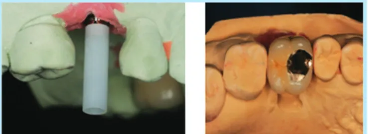
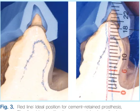
으로 치우쳐 식립된 경우나 근원심으로 경사진 경우에서는 나사 유지형 보철물의 사용이 추천되지 않는다. 시멘트 유지 형 보철을 위한 전치부 임프란트는 임프란트 고정체의 장축 이 치아의 절단연을 통과하도록 식립하는 것이 이상적이다7 (Fig. 3). 그러나 협설측 및 근원심으로 약간 치우쳐 식립된 경우에도 제공되는 angled abutment가 허용하는 범위 내에 서는 심미적 보철을 위한 절충이 가능하다(Fig. 4). 임상에서 임프란트 식립시 협설측의 치조골 소실이 관찰되어 이상적인 임프란트 식립 각도를 얻을 수 없는 경우를 종종 볼 수 있다.
임프란트의 외과적 수술의 발전으로 인하여 이러한 경우에서 도 치조골 이식이 선행되거나 동반됨으로서 과거와 달리 이 상적인 위치로의 임프란트 식립이 대부분 이루어질 수 있지 만 임프란트 고정체의 초기고정을 얻기 위해 이식 골보다는 기존 골에 임프란트가 식립되게 하거나 또는 골 이식량의 제 한 등으로 어느 정도의 임프란트의 식립각도의 변화가 있을 수 있다. 이러한 경우, 임프란트 식립 각도가 협설측 또는 근
Fig. 3. Red line: Ideal position for cement-retained prosthesis.
Blue line: Ideal position for screw-retained prosthesis.
Chae-Heon Chung et al. : The Classification and Comparison of Implant Prosthesis according to Types of Retention. Part I: Screw Retained Prosthesis vs Cement Retained Prosthesis. Implantology 2010
원심측의 경사시 나사 유지형 보철물의 제작이 가능한 위치 인지 또는 시멘트 유지형 보철제작이 가능한지를 고정체 식 립전에 확인하여야 하고 또한 각 회사에서 제공하는 angled abutment의 범위도 숙지하고 있음으로서 이와 같은 각도의 이상으로 인한 문제를 보철적으로 절충할 수 있는 범위내에 임프란트 식립이 이루어져야 한다.
3. 장,단점의 비교
나사 유지형 보철의 가장 큰 장점은 탈부착이 가능하다는 점(retrievability)이다. 이는 임프란트 고정체의 동요도 측정 이나 치주낭 측정등 임프란트 구조물의 정기적인 검진을 가 능하게 하고 각 구조물들의 주기적인 세척이 가능함으로서 위생적인 면에서도 유리하며 또한 접촉상실이나 보철물의 파
절 등의 문제가 발생되었을 때 수리를 위한 접근을 용이하게 한다. 또한 나사 유지형 보철은 최종 보철의 적합을 위해 시멘 트를 사용하지 않음으로서 임프란트 식립 깊이가 깊은 경우 치은열구내로 치과용 시멘트가 들어가 제거가 되지 않아 발 생될 수 있는 잇몸의 염증반응이나 이로 인한 치조골 소실 등 의 위험이 없는 장점이 있다(Fig. 5). 보철물의 유지력에 있어 서, 시멘트 유지형 임프란트 보철은 유지의 증가를 위해 수직 적 요소를 요구하는 반면, 나사 유지형 임프란트 보철물은 사 용가능한 지대주의 높이가 5mm 이하인 경우에도 나사에 의 해 유지됨으로서 더 많은 힘에 저항할 수 있다. 따라서 수직 악간거리가 짧아 유지력의 소실이 예상되는 경우에도 시멘트 유지형 보철보다 사용이 더 유리하다(Fig. 6). 나사 유지형 보 철물의 단점으로는 기존 지대주와 주조 접합되는 금속이 사 Fig. 4. Angled abutment can be used to correct implant angulation.
Chae-Heon Chung et al. : The Classification and Comparison of Implant Prosthesis according to Types of Retention. Part I: Screw Retained Prosthesis vs Cement Retained Prosthesis. Implantology 2010
Fig. 5. Screw-retained prosthesis for deep implant position.
Chae-Heon Chung et al. : The Classification and Comparison of Implant Prosthesis according to Types of Retention. Part I: Screw Retained Prosthesis vs Cement Retained Prosthesis. Implantology 2010
Fig. 6. Screw-retained prostheses for small interocclusal spaces.
Chae-Heon Chung et al. : The Classification and Comparison of Implant Prosthesis according to Types of Retention. Part I: Screw Retained Prosthesis vs Cement Retained Prosthesis. Implantology 2010
용되어야 하므로 금합금(precious metal)만으로만 제작이 가 능하여 보철 비용이 비싸진다는 단점과 기공과정이 어렵고 복 잡하며 나사풀림을 비롯하여 나사 파절, 수동적 적합(passive fit)의 상실, 비 심미성 등이 문제점으로 지적되어 왔다8-11. 이 중 가장 흔히 야기되는 나사 풀림은 상부 보철물이 인상채득 이나 주조시의 오차로 인하여 불완전하게 적합된 경우, 부적 절한 디자인으로 인한 교합적 과하중, abutment screw가 정 해진 torque보다 덜 조여진 경우 등이 원인이다. 이와 같은 문제점을 줄이기 위해서 여러 가지 임상적, 기공적 방법들이 소개되어 왔다12,13. 일반적으로 나사는 적절한 조임력 (clamping force)을 제공하기 위해 그들의 yield strength의 50~75%까지 조여져야 하고14 초기장착에서 coping fixa- tion screw는 최종 torque의 2/3~3/4까지 조여져야 한다.
이후 나사의 조여짐을 확인하고 압통 또는 불편감 같은 임상 징후가 기록될 수 있도록 2~3일 후 다시 내원시켜야 하고 대
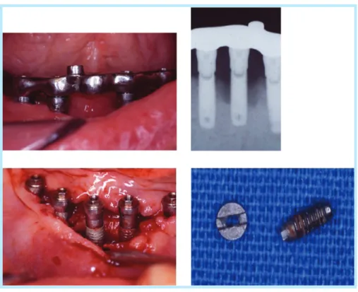
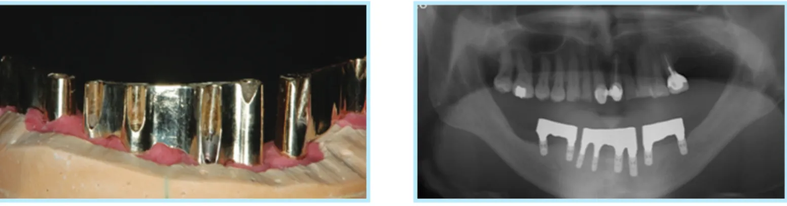
략 4주 후 임프란트 회사별 매뉴얼에서 권하는 각 screw의 torque에 따라 완전히 조이는 것이 추천된다. 이와 같은 나사 의 적절한 torque의 부여 뿐 아니라 나사의 코팅이나 재질의 개발 등을 통하여 나사 풀림을 줄이기 위한 많은 방법들이 소 개되고 있다. 다수의 임프란트를 연결하여 고정성 보철을 제 작하거나 무치악 환자에서 2개나 4개의 임프란트를 연결하여 bar를 제작할 때 대부분 사용되는 나사 유지형 보철에서는 수 동적 적합(passive fit)의 상실로 인한 문제가 발생될 수 있다
9,15. 이는 인상 채득시, 모형 제작시, 주조시에 임상적 또는 기 술적 오차에 의해 발생되며 수동적 적합의 소실은 차후 나사 풀림과 파절, 임프란트 구성체의 파절, 골유착의 파괴 등의 문 제를 야기할 수 있다(Figs. 7, 8). 따라서 정확한 임상과 기공 과정을 통하여 수동적 적합을 이루기 위한 노력이 필요하며 long span의 보철물인 경우 one piece casting보다는 sec- tional casting을 시행한다던지 또는 납착이나 EDM 등의 방
Fig. 7. Screw fracture and surrounding bone resorption due to failure of passive fit.
Chae-Heon Chung et al. : The Classification and Comparison of Implant Prosthesis according to Types of Retention.
Part I: Screw Retained Prosthesis vs Cement Retained Prosthesis. Implantology 2010
법을 이용하여 수동적 적합을 이루는 방법들이 사용될 수 있 다16-20(Fig. 9).
나사 유지형 보철과 비교하여 시멘트 유지형 보철의 장점은 passive casting이 가능한 점, screw hole이 형성되지 않음
으로 교합압이 고정체에 수직적으로 가해질 수 있도록 디자 인 할 수 있고 교합면 재료의 파절이 적다는 점, 심미적이고 임상 및 기공과정이 더 간편하고 비용이나 시간이 적게 들며 지대주와 보철물사이에 주조로 인한 결함이 없다는 점이다 Fig. 8. Fracture of implant fixture due to ill-fitting prosthesis.
Chae-Heon Chung et al. : The Classification and Comparison of Implant Prosthesis according to Types of Retention. Part I: Screw Retained Prosthesis vs Cement Retained Prosthesis. Implantology 2010
Fig. 9. Multiple implants are connected using 3-piece sectional casting.
Chae-Heon Chung et al. : The Classification and Comparison of Implant Prosthesis according to Types of Retention. Part I: Screw Retained Prosthesis vs Cement Retained Prosthesis. Implantology 2010
21,22. 이러한 시멘트 유지형 임프란트 보철물은 임프란트 고 정체에 잘 적합된 기성 지대주 위에 보철물이 시멘트로 접착 됨으로서 수동적으로 안정된 환경을 제공한다. 상부보철물이 연결된 지대주에 비수동적으로 장착되는 경우에도 보철물 내 면에 fit checker 등을 사용하여 조정하여 안착시킴으로서 절 단과 납착의 과정이 필요 없는 경우가 대부분이다. 지금까지 많은 술자들은 시멘트 유지형이 탈부착이 불가능하다는 이유 로 이를 피하는 경향이 있었다. 그러나 시멘트 유지형 보철물 도 적절한 접착제(cement)가 사용될 때는 재적합이 가능하 다. 최종 접착제는 재적합을 위해서는 너무 강하므로 임플랜 트 유지를 위해서는 추천되지 않는다23. 이상적인 경사도와 긴 측벽을 가진 지대주위에 장착되는 상부 보철물의 장기간 유지를 위해 임시 접착제의 사용이 추천되며 Temp-bond cement과 petroleum jelly를 혼합하거나 Temp-bond cement을 단독으로 사용하는 방법이 소개되었다24,25. 최근 에는 임프란트 시멘트 유지형 보철을 위한 접착제가 따로 시 판되고 있으며 이는 기존의 temporary cement보다 유지는 강하고 흘러나온 여분의 시멘트가 깨끗하게 제거가 되는 장 점이 있다(Fig. 10).
4. 인상채득 방법의 비교
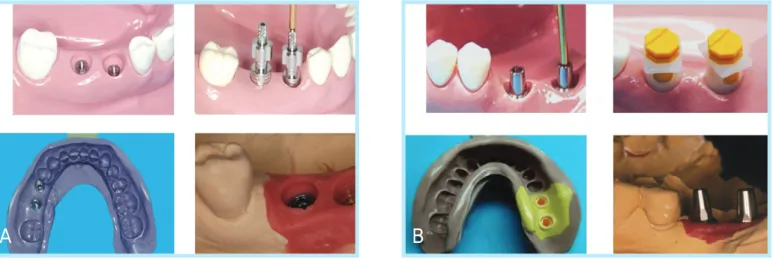
임프란트 보철을 위한 인상채득은 고정체의 위치를 모델 상 으로 인기하는 Implant level impression과 구강 내에서 지 대주를 연결하여 이를 모델 상으로 인기하는 abutment level impression으로 나눌 수 있다(Fig. 11). 이 중 나사 유지형 보 철을 위한 인상채득은 임프란트 고정체에 transfer type impression coping이나 pick-up impression coping을 연 결하여 implant level impression을 채득하는 것이다. 임프 란트 고정체의 위치 이전이 주모형에 이루어진 후 상부보철 물을 위한 지대주를 모형 상에 연결하고 wax-up 하여 주조 한다. 반면, 시멘트 유지형 보철을 위한 인상채득은 지대주가 일체형인가 분리형인가에 따라 implant level impression이 나 abutment level impression을 채득한다5(Fig. 12). 지대 주와 이를 고정하는 나사가 일체형인 경우의 대표적인 경우 가 solid abutment이다. 이는 인상채득을 위하여 지대주를 원하는 torque로 조이고 구강내에서 abutment level impression을 채득한다. 즉 지대주가 채결된 상태의 인상을 채득하여야 한다. 만약 implant level impression을 채득하 고 모형 상에서 일체형 지대주를 연결한 후 보철을 완성한 경 우 지대주를 구강 내에서 조이고 보철물을 삽입할 때 모형상 과 일치하지 않은 경우가 발생된다. 이는 모형상에서 조임력 과 구강 내에서 조임력의 차이로 인하여 발생되고 고정체가 기울어져 식립 되어 지대주의 삭제가 시행된 경우에서는 특 히 위치변화로 인한 보철물의 장착이 불가하여 재제작이 필 요한 경우가 발생될 수 있다. abutment-level impression은 지대주를 장착하고 일반적인 인상채득법과 유사하게 압배사 를 이용하여 치은 압배를 시행하고 고무인상재로 채득하는 방법이 있고 또는 회사에게 제공하는 인상용 cap을 이용하여 transfer type으로 채득하는 방법이 있다. 분리형 지대주는 지대주에서 나사가 분리되는 형태를 말하며 대표적인 지대주 는 straight abutment와 angled abutment를 들 수 있다.
단일치에 지대주의 풀림을 방지하기 위한 engaged type 분 리형 지대주는 고정체 내부의 일정한 위치 내에 위치되고 지 Fig. 10. Temporary cement for implant crown.
Chae-Heon Chung et al. : The Classification and Comparison of Implant Prosthesis according to Types of Retention. Part I: Screw Retained Prosthesis vs Cement Retained Prosthesis. Implantology 2010
대주와 임프란트 고정체를 연결하는 나사로 연결된다. 이와 같은 형태의 분리형 지대주를 사용하는 경우는 implant level impression과 abutment level impression이 모두 가능하 다. 즉 정확한 위치의 고정체의 이전이 가능하다면 모형 상에 지대주의 위치가 정확하게 고정체 analogue와 연결되고 이 를 나사로 조이므로 다시 구강내로 이전시에도 동일한 위치 로의 지대주의 이전이 가능하기 때문이다. 따라서 임상 및 기 공적인 오차가 적은 방향으로 술자의 선호도에 따라 인상방
법을 선택할 수 있다. 여러 개의 지대주를 연결하는 보철의 경 우 풀림의 가능성이 적으므로 non engaged type의 분리형 지대주를 사용할 수 있다. Non engaged type의 경우에서도 implant level impression이나 abutment level impression 이 모두 가능하다. 단, implant level impression을 채득하고 모델 상에서 지대주를 연결하여 최종보철물을 완성한 후, 이 를 구강내 고정체에 연결할 때 정확한 위치로의 이전이 중요 하다. 즉, non engaged type의 경우 지대주 하부의 형태가 둥글어서 고정체의 정확한 위치로 장착되는 형태가 아니므로 duraraly나 pattern resin을 이용하여 jig을 미리 만듦으로 서 모델상의 위치를 구강내로 정확히 이전시키는데 도움이 된다(Fig. 13).
5. 교합적인 비교
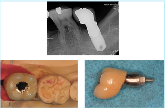
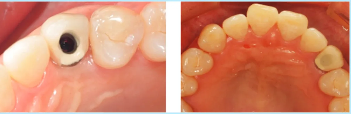
치아의 교합면 위의 나사의 접근을 위한 screw hole은 비 심미적이며 적절한 교합의 부여를 방해한다. 치아마다 교합 table의 면적은 다르지만 대부분 소구치는 4.5~5.5mm, 대 구치는 5.0~6.0mm이며 screw hole은 대개 3.0mm 정도이 다. 이는 구치에서 최소 30%, 소구치에서는 50% 이상의 교 Fig. 11. Implant-level impression and abutment-level impression. ((AA)) Implant-level impression, ((BB)) abutment-level
impression.
Chae-Heon Chung et al. : The Classification and Comparison of Implant Prosthesis according to Types of Retention. Part I: Screw Retained Prosthesis vs Cement Retained Prosthesis. Implantology 2010
A B
Fig. 12. One-piece and two-piece abutment for cement-retained prosthesis.
Chae-Heon Chung et al. : The Classification and Comparison of Implant Prosthesis according to Types of Retention. Part I: Screw Retained Prosthesis vs Cement Retained Prosthesis. Implantology 2010
One-piece abutment Two-piece abutment
합면을 차지한다3(Fig. 14). 임프란트 고정체의 장축을 향한 적절한 교합을 형성 시 이러한 screw hole은 교합면의 이상 적인 형성을 어렵게 한다. 따라서 시멘트 유지형 임프란트 보 철물이 나사 유지형 보철에 비해 심미성과 교합 모두에서 더 우수하다 할 수 있다. 이러한 효과는 교합 형성시 전방과 측방 운동에도 영향을 준다. 즉 시멘트 유지형으로 보철수복시 전 방과 측전방 운동을 형성할 수 있도록 모든 치아의 해부학적 형태를 형성할 수 있는 반면, 나사 유지형은 전방과 측전방 운 동시 부드러운 활주를 위한 견치와 중절치에 대한 적절한 해 부학적 형태의 부여를 어렵게 한다(Fig. 15). 임프란트에 가해
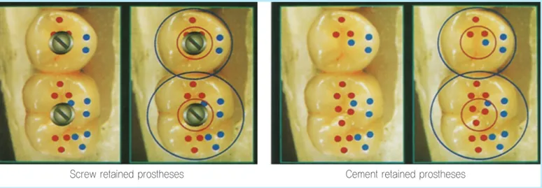
지는 하중은 장축을 향한 axial loading과 장축에서 벗어난 offset loading으로 나눌 수 있다. axial loading이 임프란트 와 임프란트-골계면에 유익한 반면 offset loading은 유해하 다 할 수 있다10,26-30. 골-임프란트 계면은 약간의 offset loading시 견딜 수 있지만 나사풀림이나 파절과 같은 보철적 합병증의 발생은 증가할 수 있다9,31. 따라서 교합력이 임프란 트의 보철물에 수직으로 가해짐으로서 임프란트 고정체에 수 직으로 전달되도록 하는 것이 이상적이다(Fig. 16). Hebel 등3 은 target, the bull's eye 개념을 소개하면서 전체적인 치아 의 교합면은 저작, 연하, 이악물기, 이갈이시 하중을 받는 부 Fig. 13. Transfer of non-engaged type two-piece abutment from model to patient using
Duralay resin jig.
Chae-Heon Chung et al. : The Classification and Comparison of Implant Prosthesis according to Types of Retention. Part I: Screw Retained Prosthesis vs Cement Retained Prosthesis. Implantology 2010
Fig. 14. Size of screw hole on the occlusal surface of premolar and molar.
Chae-Heon Chung et al. : The Classification and Comparison of Implant Prosthesis according to Types of Retention. Part I: Screw Retained Prosthesis vs Cement Retained Prosthesis. Implantology 2010
분으로 Target 모양을 이루고, 이중 이상적인 수직하중이 가 해질 수 있는 임프란트 교합면의 중앙부위를 bull's eye라 명 명하면서 이 부위 밖에서 나타나는 모든 접촉이나 힘은 off- set loading으로 작용한다 하였다. 따라서 시멘트 유지형 임 프란트 보철물의 경우는 bull's eye내에 다수의 접촉점을 제 공함으로서 수직적인 힘이 임프란트 고정체로 가해질 수 있 는 반면, 나사 유지형 임프란트 보철물의 경우는 screw hole
의 형성으로 인하여 bull‘s eye내에 제한된 접촉점을 제공하 게 됨으로써 수직적인 힘이 임프란트에 가해지는 것을 방해 한다고 하였다(Fig. 17). 나사 유지형 보철물은 나사를 정해진 torque로 조인 후 screw hole을 최종적으로 아말감이나 레 진으로 폐쇄한다. 이 때 고무재질의 stopper 또는 작은 cot- ton 이나 caviton으로 나사 head의 보호하고 차후 나사풀림 들이 발생하였을 때 접근을 용이하게 한다. 수직적인 교합 하 Fig. 15. Smooth pathway of canine guidance can be impeded by screw hole.
Chae-Heon Chung et al. : The Classification and Comparison of Implant Prosthesis according to Types of Retention. Part I: Screw Retained Prosthesis vs Cement Retained Prosthesis. Implantology 2010
Fig. 16. Axial loading and offset loading on the implant crown.
Chae-Heon Chung et al. : The Classification and Comparison of Implant Prosthesis according to Types of Retention. Part I: Screw Retained Prosthesis vs Cement Retained Prosthesis. Implantology 2010
중의 전달을 위하여 screw hole을 폐쇄한 레진이나 아말감 수복물상에 교합을 형성하기도 하지만 이는 마모가 쉽게 되 고 탈락의 가능성도 있으므로 나사구멍 주변으로 접촉을 형 성한다. 교합면까지 도재 수복물로 수복하는 경우 나사구멍 주변의 교합의 형성은 도재의 파절(procelain chipped off) 을 야기할 수 있으므로 나사구멍 주변에 1~2mm 의 금속 접
촉점을 형성하고 그 외부위에 도재가 형성되도록 디자인의 변경을 줌으로서 도재의 파절을 줄일 수 있다(Fig. 18).
결론
이상으로 임프란트 최종 보철물의 유지형태에 따른 나사 유 지형 보철과 시멘트 유지형 보철에 대해 살펴보았다. 어떠한 유지형태의 사용이든 최종적인 목표는 기능적이고 심미적인 보철물의 완성이다. 이를 위해서는 임프란트 수술 전 치료 계 획단계에서의 최종 유지형태를 결정하는 것이 우선되어야 한 다. 이는 환자의 심미적 기대도와 추후 임프란트 보철물의 예 측되는 모양의 차이에 대해 미리 환자에게 정보를 제공할 수 있고 수술시 임프란트 식립의 위치에 영향을 줄 수 있으며 교 합면의 형태에 따른 교합위치의 변화와 고정체에 가해지는 하중의 방향등의 변화로 인한 임프란트 보철의 예후에도 영 향을 주므로 임프란트 치료에서 있어서 매우 중요한 요소임 을 잊지 말아야 할 것이다. 다음 호에서는 Part II로 나사 유
Ⅲ
Fig. 17. Target and the bull’s eye concept. Blue Circle: Target, Red Circle: Bull’s Eye (Hebel, 1997).
Chae-Heon Chung et al. : The Classification and Comparison of Implant Prosthesis according to Types of Retention. Part I: Screw Retained Prosthesis vs Cement Retained Prosthesis. Implantology 2010
Screw retained prostheses Cement retained prostheses
Fig. 18. The gold occlusal contact designed around screw hole to prevent porcelain fracture.
Chae-Heon Chung et al. : The Classification and Comparison of Implant Prosthesis according to Types of Retention. Part I: Screw Retained Prosthesis vs Cement Retained Prosthesis. Implantology 2010
지형과 시멘트 유지형의 장점을 복합하여 응용된 나사-시멘 트 복합 유지형 보철물(SCP)에 대해 소개하고자 한다.
Reference
1. Misch CE. Screw-retained versus cement-retained implant supported prostheses Pract Perio Aesthe Dent. 1995; 7: 15-18.
2. Melton AB. Fastening the implant prosthesis: cemented, screw-retained, or screwmented. Int J Dental Symposia. 1997; 4: 58.
3. Hebel KS, Gajjar RC. Cement-retained versus screw-retained implant restoration: Achieving optimal occlusion and esthetics in implant den- tistry. J Prosthet Dent. 1997; 28-35: 77.
4. Chee W, Felton DA, Johnson PF, et al. Cemented versus screw-retained implant prostheses: Which is better? [current issues forum]. Int J Oral Maxillofac Implants 1999; 14: 137-141.
5. Misch CE. Contemporary implant dentistry. 2nd ed. St. Louis: Mosby Inc.; 1999. p. 549-593.
6. Kim SG, Park JU, Jeong JH, et al. In vitro evaluation of reverse torque value of abutment screw and marginal opening in a screw and cement retained implant fixed partial denture design. Int J Oral Maxillofac Implants. 2009; 24: 1061-1067.
7. Misch CE. Contemporary implant dentistry. 2nd ed. St. Louis: Mosby Inc.; 1999. p. 397-428.
8. Beauty K. The role of screw in implant systems. Int J Oral Maxillofac Implants. 1994; 9: 52-54.
9. Kallus T, Bessing C. Loose gold screws frequently occur in full arch fixed prostheses supported by osseointegrated implants after 5 years. Int J Oral Maxillofac. Implants. 1994; 9: 169-178.
10. Brunski JB. Biomaterials and biomechanics in dental implant design. Int J Oral Maxillofac Implants. 1988; 3: 85-97.
11. Carlson B, Carlsson GE. Prosthodontic complications in osseointegrated dental implant treatment. Int J Oral Maxillofac Implant. 1994; 9: 90-94.
12. Hurson S. Practical Clinical guideline to prevent screw loosening. Int J Dental Symposia. 1995; 3: 22-25.
13. McGlumphy EA, Mendel DA, Holloway JA. Implant screw mechanics.
Dent Clin North Am. 1998; 42: 71-89.
14. Shingley J. Mechanical engineering design, 3rd ed . New York:
McGraw Hill; 1987. p. 244.
15. Jemt T, Carlsson L, Boss A, et al. In vivo load measurements on osseointegrated implants supporting fixed or removable prostheses: a comparative pilot study. Int J Oral Maxillofac Implants. 1991; 6: 413- 417.
16. Linehan AD, Windeler AS. Passive fit of implant-retained prosthetic superstructures improved by electric discharge machining. J Prosthodont. 1994; 3: 88-95.
17. Bloem TJ, Baxter WD Jr, Vivas J. Spark erosion implant prosthetics in the management of an acquired maxillofacial defect. J Mich Dent Assoc. 1996; 78: 50, 52-54.
18. LaBarge KW. Electrical discharge machining. J Dent Technol. 1997;
14: 19-22.
19. Romero GG, Engelmeier R, Powers JM, et al. Accuracy of three correc- tive techniques for implant bar fabrication. J Prosthet Dent. 2000; 84:
602-607.
20. Fischer J, Thoma A, Suter A, et al. Misfit of suprastructures on implants processed by electrical discharge machining or the Cresco method.
Quintessence Int. 2009; 40: 515-522.
21. Keith SE, Miller BH, Woody RD, et al. Marginal discrepancy of screw- retained and cemented metal ceramic crowns on implant abutments. Int J Oral Maxillofac Implants. 1999;14:369-378.
22. Guichet DL, Caputo AA, Choi H, et al. Passivity of fit and marginal opening in screw- or cement-retained implant fixed partial denture designs. Int J Oral Maxillofac Implants. 2000; 15: 239-246.
23. Ekfeldt A, Carlsson GE, Borjesson G. Clinical evaluation of single- tooth restorations supported by osseointegrated implants: a retrospective study. Int J Oral Maxillofac Implants. 1994; 9: 179-183.
24. Breeding LC, Dixon DL, Bogacki MT, et al. Use of luting agents with an implant system: Part 1. Prosthet Dent. 1992; 68: 737-741.
25. Bastos VFP, Gomez Perez E, Breda M. Alternative method for retention and removal of cement-retained implant prostheses. J Prosthet Dent.
2001; 86: 181-183.
26. Misch CE, Bidez MW. Implant-protected occlusion: a biomechanical rationale. Compend Contin Dent Educ. 1994; 15: 1330-1343.
27. Rangert B, Jemt T, Jorneus L. Forces and moments on Branemark implants. Int J Oral Maxillofac Implants. 1989; 4: 241-247.
28. Weinberg LA. The biomechanics of force distribution in implant-sup- ported prostheses. Int J Oral Maxillofac Implants. 1993; 8: 19-31.
29. Katona T, Goodacre CJ, Brown DT, et al. Force-moment systems on single maxillary anterior implants: effects of incisal guidance, fixture orientation, and loss of bone support. Int J Oral Maxillofac Implants.
1993; 8: 512-522.
30. Ogiso M, Tabata T, Kuo PT, et al. A histologic comparison of the func- tional loading capacity of an occluded dense apatite implant and the nat- ural dentition. J Prosthet Dent. 1994; 71: 581-588.
31. Celletti R, Pameijer C, Bracchetti G, et al. Histologic evaluation of osseointegrated implants restored in nonaxial functional occlusion with preangled abutments. lnt J Perio Rest Dent. 1995; 15: 563-573.
교신저자 : 손미경
우편번호 (501-759) 광주 광역시 동구 서석동 375 조선대학교 치의학전문대학원 보철학교실
Tel : 82-62-220-3825 Fax : 82-62-227-2363
E-mail : [email protected] 원고접수일 : 2010년 5월 26일 게재확정일 : 2010년 6월 12일
Reprint requests : Mee-Kyoung Son
Department of Prosthodontics, School of Dentistry, Chosun University, 375, Seosuk-Dong, Dong-Gu,
Gwangju, 501-759, Republic of Korea Tel : 82-62-220-3825
Fax : 82-62-227-2363
E-mail : [email protected] Received for publication : May 26, 2010 Accepted for publication : June 12, 2010