1. Introduction
In recent years, super-hydrophobic coatings have at- tracted attention in many fields because they have unique characteristics such as anti-sticking, anti-icing, anti-con- tamination, anti-corrosion and self-cleaning [1-5]. Surface with a contact angle higher than 150 degrees between wa- ter and the surface is called superhydrophobic surfaces.
A representative example of a superhydrophobic surface present in nature is a lotus. In 1997, German botanists W. Barthlott and C. Neinhuis studied the surface structure of lotus. The surface of the petal was found to be covered with a low surface energy material and had a complex surface roughness of nano and micro size [2]. Since then, many researchers have been studying to fabricate a rough surface on a material with low surface energy or surface modification of a rough surface with low surface energy to realize an artificial superhydrophobic coating.
Various fluoropolymers are mainly used to make hydro- phobic coatings. These coatings contain fluorine in the polymer chain and have unique properties such as heat
resistance, chemical resistance, stain resistance and low surface energy compared to other hydrocarbon polymers [19,20].
Polyvinylidene fluoride (PVDF) is mainly used fluo- ropolymer coating material, because of comparatively ex- cellent compatibility with solvents, low surface energy (25 dynes/cm), excellent mechanical strength, thermal stabil- ity, weather ability and chemical resistance [9,12].
Various studies have been conducted to make super- hydrophobic coatings by adding various pigments such as fumed silica to PVDF coatings [4-11]. Fumed silica has hydrophilic properties because it has many hydroxyl groups on the surface. Thus, if fumed silica is added as a pigment without any treatment, it is easily agglomerated and difficult to obtain good dispersion in the coating [13].
To solve these problems, the hydrophobic surface mod- ification of fumed silica has been used to improve the dispersibility [4].
Recently, the use of commercial hydrophobic fumed silica was available and it must be added more than 70 wt% of the resin to make hydrophobic coating. In the present study, a new modification process of the fumed silica was carried out using two modifiers, trimethyl-
Analysis of PVDF Coating Properties with Addition of Hydrophobically Modified Fumed Silica
Nam Kyu Lee, Young Hoon Kim, Tae Gyu Im, Dong Uk Lee, MinYoung Shon, and Myung Jun Moon† Department of Industrial Chemistry, Pukyong National University, Busan, 48547, Republic of Korea
(Received October 25, 2019; Revised November 25, 2019; Accepted November 25, 2019)
In this study, hydrophobically modified fumed silica was added to the PVDF coating to improve corrosion protection performance. Two types of silane modifiers, trimethylchlorosilane (TMCS) and hexamethyldisilazane (HMDZ), were used for hydrophobic modification of the fumed silica. The composition of modified fumed silica was analyzed by Fourier transform infrared, X-ray photoelectron spectroscopy, and elemental analysis.
The dispersion of modified fumed silica in the PVDF coating was observed by the transmission electron microscopy, and the hydrophobicity of PVDF coating was analyzed by the water contact angle. Surface properties were examined by the field emission scanning electron microscopy and scanning probe microscopy.
Potentiodynamic polarization was conducted to confirm corrosion protection performance of PVDF coating in terms of hydrophobically-modified fumed silica contents. As a result, the average surface roughness and the water contact angle of the PVDF coating increased with modifier contents. The results of the potentiodynamic polarization test showed an increase of the Ecorr values with increase of the hydrophobicity of PVDF coating.
Thus, it clearly indicates that the corrosion protection performance of PVDF coating improved with the addition of the hydrophobic-modified fumed silica that prevents the penetration of moisture into the PVDF coating.
Keywords: Polyvinylidene fluoride, Hydrophobic modification, Fumed silica
†Corresponding author: [email protected]
chlorosilane (TMCS) and hexamethyldisilazane (HMDZ) to achieve hydrophobic property. Then, the corrosion pro- tection performance of PVDF coatings with fumed silica modified with TMCS and HMDZ was compared to that of PVDF coatings with commercial fumed silica.
2. Experimental Methods 2.1. Materials
For hydrophobic surface modification, trimethyl- chlorosilane (TMCS, Tokyo chemical industry, Japan) and hexamethyldisilazane (HMDZ, Tokyo chemical industry, Japan) were used as surface modifiers for fumed silica (Sigma-Aldrich, U.S.). Triethylamine (TEA, Junsei chem- ical, Japan) and trifluoroacetic acid (TFA, Daejung chem- ical, Korea) were used as catalysts and n-hexane (Daejung chemical, Korea) and ethyl alcohol (EtOH, Daejung chem- ical, Korea) were used as solvents. The PVDF coating
solution was prepared by using PVDF powder (Sigma- Aldrich, U.S.) and N, N-dimethylformamide (DMF, Junsei chemical, Japan). The hot-rolled steel sheets were used as substrate materials for coating. The surface of steel sheets was blasted using 2 μm size of aluminum oxide, washed with acetone (Daejung chemical, Korea), and then coated with a one-component polyurethane primer. (PPG, Korea).
2.2. Surface modification of Fumed silica 2.2.1. Heat treatment of fumed silica
To improve the surface modification efficiency of fumed silica, heat treatment was carried out before mod- ification [15]. The heat treatment was conducted to re- move the adsorbed water on the surface of fumed silica and in order to reduce the ratio of hydrogen-bonded hy- droxyl groups not involved in the reaction. It also in- creases the proportion of free hydroxyl groups, resulting in improving the efficiency of the modification [15]. In the present study, fumed silica was heated to 800 °C for 4 hours with a heating rate of 10 °C/min by a furnace (AJ-SB1, Ajeon Heating Industrial, Korea)
2.2.2. The hydrophobic surface modification of fumed silica using TMCS
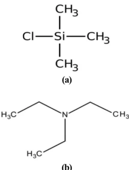
The chemical structure of TMCS and TEA for surface modification are shown in Fig. 1. In surface modification process, 10 g of fumed silica was put into the 1 liter of n-hexane, followed by stirring at 60 °C and 25 ml of TEA was added as a catalyst, then TMCS was added 10, 30, 50, 70 and 80 wt% of the weight of fumed silica, respectively.
After stirring at 60 °C for 12 hours, the aspiration process was carried out using n-hexane and EtOH to remove un- reacted materials then dried at 60 °C for 12 hours. The dried modified fumed silica was stored after grinding. Fig.
2 shows the reaction mechanism.
(a)
(b)
Fig. 1 Chemical structure of materials during modification process. (a) TMCS, (b) TEA
Fig. 2 Chemical reaction mechanism of fumed silica and TMCS.
2.2.3. hydrophobic surface modification of fumed silica using HMDZ
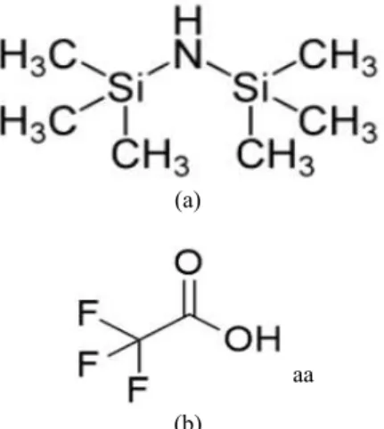
The chemical structure of HMDZ and TFA for surface modification is shown in Fig. 3. In surface modification process, 10 g of fumed silica was put into the 1 liter of n-hexane, followed by stirring at 60 °C and 3 ml of TFA was added as a catalyst, then HMDZ was added 10, 30, 50, 70 and 80 wt% of the weight of fumed silica, respectively. The aspiration process was carried out using n-hexane and EtOH to remove unreacted materials then dried at 60 °C for 12 hours. The dried modified fumed silica was stored after grinding. Fig. 4 shows the reaction mechanism and Table 1 shows the sample names and syn- thesis conditions.
2.3. Manufacture of PVDF coating solution with hydrophobically modified fumed silica
The 7 wt% of the PVDF solution was prepared by dissolving PVDF powder in DMF and stirring at 50 °C until the solution becomes transparent. After that, the
7 wt% of PVDF solution and modified fumed silica were mixed with a weight ratio of 1:1 and the PVDF solution was stirred and sonicated at room temperature for 1 hour until it becomes transparent. Also, in the same process
Table 1 The sample name and modification conditions
Sample Solvent Modifier Synthesis time Concentration(wt%)
S - - - -
T10
n-hexane TMCS 12h
10
T30 30
T50 50
T70 70
T80 80
H10 10
H30 30
H50 n-hexane HMDZ 12h 50
H70 70
H80 80
Fig. 4 Chemical reaction mechanism of fumed silica and HMDZ.
(a)
aa
(b) Fig. 3 Chemical structure of materials during the modification process. (a) HMDZ, (b) TFA
as above, PVDF solutions were prepared with the addition of commercial hydrophobic fumed silica, AEROSIL®
R816 (Evonik) and AEROSIL® R976 (Evonik).
2.4. Specimens fabrication and coating treatment The hot-rolled steel sheet was blasted with 2 μm size of aluminum oxide and washed with acetone for 10 mi- nutes in the ultrasonic cleaner. Urethane primer was ap- plied to the blasted specimen using a no. 24 bar coater and cured at 300 °C for 5 minutes, then PVDF coating was sprayed and cured at 110 °C for 4 hours. The dry coating film thickness was 21 ± 2 μm. Table 2 shows the names of specimens according to the types of fumed silica in the PVDF coating.
2.5. Analysis
FT-IR (Fourier transform infrared, Nicolet iS10, Thermoscientific U.S.A.) was used to analyze the chemical functional group of the surface-modified fumed silica. XPS (X-ray photoelectron spectroscopy, MultiLab2000, 0.5 eV Al Kα, Thermo VG Scientific, U.K.) and EA (Elemental analysis, Leco Truspec Micro, U.S.A.) were used to ana- lyze surface material composition changes of the sur-
face-modified fumed silica. The dispersion of fumed silica in toluene was observed by TEM (Transmission Electron Microscopy, Tungsten Filament type, HITACHI H-7500, Japan). For TEM analysis, 0.1 wt% of fumed silica was dispersed in 20 g of toluene by sonication and stirring.
The hydrophobicity of the coatings according to the sur- face modification of fumed silica, was analyzed using the water contact angle measurement (SEO Pheonix150, Korea). The surfaces of PVDF coatings were observed us- ing FE-SEM (TESCAN MIRA 3 LMH In-Beam, Czech).
The surface roughness of PVDF coating with the contents of fumed silica was measured by scanning probe micro- scopy (BRUKER Icon-PT-PLUS, USA). Potentiodynamic polarization analysis was performed to evaluate the corrosion protection performance using PARSTAT 2273 (EG&G Princeton applied research, U.S.A.)
3. Results
3.1. Analysis of fumed silica
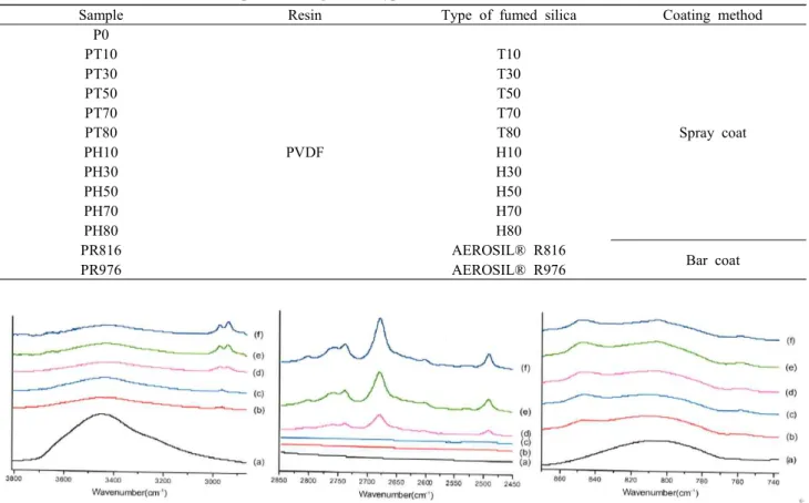
3.1.1. Fourier transform infrared spectroscopy (FT-IR) Fig. 5 shows the FT-IR spectrum of 3800 ~ 2860 cm-1 and 870 ~ 740 cm-1 region depending on the amount of Table 2 The name of the coated sample according to the type of fumed silica
Sample Resin Type of fumed silica Coating method
P0
PVDF
Spray coat
PT10 T10
PT30 T30
PT50 T50
PT70 T70
PT80 T80
PH10 H10
PH30 H30
PH50 H50
PH70 H70
PH80 H80
PR816 AEROSIL® R816
Bar coat
PR976 AEROSIL® R976
Fig. 5 FT-IR spectrum according to the amount of TMCS. NS, (b) T10, (c) T30, (d) T50, (e) T70, and (f) T80
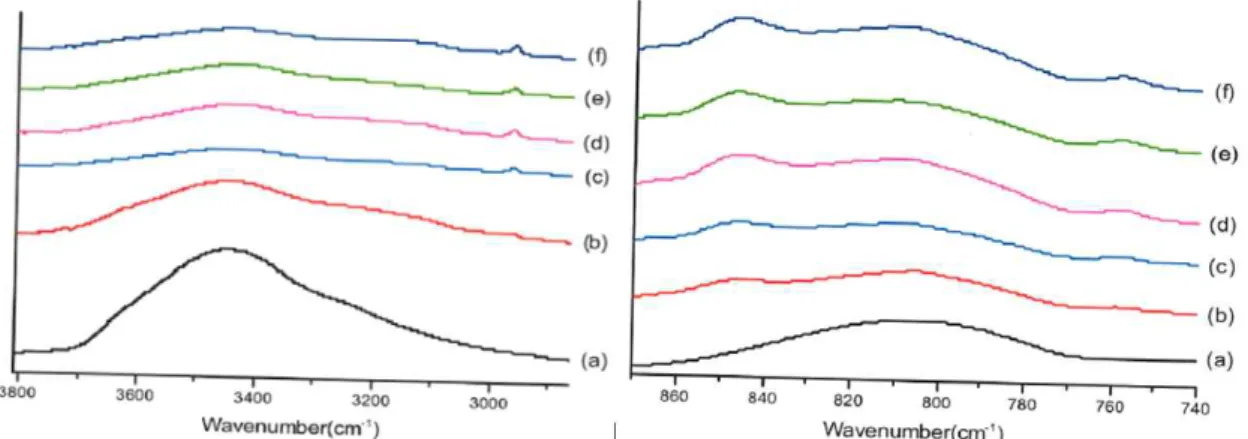
TMCS, and Fig. 6 shows the FT-IR spectrum of 3800
~ 2860 cm-1 and 870 ~ 740 cm-1, depending on the amount of HMDZ.
3.1.2. X-ray photoelectron spectroscopy (XPS)
The surface composition of fumed silica was analyzed by X-ray photoelectron spectroscopy (XPS) Si2p spectrum with an increasing amount of modifier during the mod-
ification process. The results are shown in Fig. 7, Fig.
8, and Fig. 9.
3.1.3. Elemental analysis (EA)
To analyze the change of the surface carbon content of modified fumed silica depending on the contents of the modifier, elemental analysis (EA) was analyzed, and the results are shown in Table 3.
3.1.4. Transmission electron microscopy (TEM)
The dispersion of fumed silica was observed using Transmission electron microscopy (TEM) and the sur- face-modified fumed silica and unmodified fumed silica were observed at 100-fold magnification as shown in Fig. 10.
3.2. PVDF coating analysis with hydrophobic surface-modified fumed silica
3.2.1. Scanning probe microscopy (SPM)
The surface roughness of PVDF coating containing fumed silica was measured by SPM in terms of modifier contents.
Fig. 6 FT-IR spectrum according to the amount of HMDZ. (a) NS, (b) H10, (c) H30, (d) H50, (e) H70, and (f) H80 Table 3 Elemental analysis of unmodified and modified fumed silica
Sample C %/mg H %/mg N %/mg
NS 0.655069 0.409446 0.3328
T10 1962482 0.85581 1.0341
T30 2.006774 0.951828 1.9433
T50 5805325 0.979675 2.4717
T70 7.743762 1.183836 3.2274
T80 9.365313 1525719 3.0425
H10 3.090976 0.773244 0.539
H30 4.841998 0.909682 1.5841
H50 4.883243 0.733199 1.0487
H70 6.21812 1.126786 0.0686
H80 8.544563 1.490909 0.7176
Fig. 7 Si 2p spectrum of NS.
(a) (b) (c)
(d) (e)
Fig. 8 Si 2p spectrum of modified fumed silica with TMCS. (a) T10, (b) T30, (c) T50, (d) T70, and (e) T80
(a) (b) c)
(d) (e)
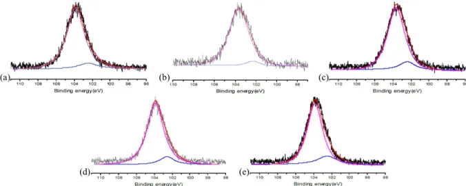
Fig. 9 Si 2p spectrum of modified fumed silica with HMDZ. (a) H10, (b) H30, (c) H50, (e) H70, and (e) H80
Table 4 The average surface roughness of PVDF coating with fumed silica
Sample Average surface roughness (nm, Ra)
P0 21.8
PT10 36.3
PT30 41.2
PT50 41.8
PT70 43.4
PT80 44.1
PH10 35.1
PH30 40.3
PH50 44.1
PH70 50.7
PH80 56.4
Table 5 Water contact angle measurement of specimens Sample Average contact angle (°)
P0 75.88
PT10 104.59
PT30 145.48
PT50 85.87
PT70 87.51
PT80 88.77
PH10 95.17
PH30 137.74
PH50 140.43
PH70 150.00
PH80 151.92
The average roughness (Ra) of each specimen is shown in Table 4.
3.2.2. Water contact angle (WCA)
To confirm the relationship between surface roughness of the coating and hydrophobicity, the contact angle measure- ment was conducted according to the type and adding contents of the modifier and the results were listed in Table 5.
3.2.3. Field emission scanning electron microscopy (FE-SEM)
The surface morphology of fumed silica in PVDF coat- ing was observed by FE-SEM at a magnification of 150,000 times. The SEM images were shown in Fig. 11 and Fig. 12.
Fig. 10 B-TEM images of fumed silica. NS, (b) T10, (c) T50, (d) T80, (e) H10, (f) H50, and (g) H80
Fig. 11 SEM images of surface morphology of PVDF coatings with TMCS. (a) P0, (b) PT10, (c) PT30, (d) PT50, (e) PT70, and (f) PT80
3.2.4. Potentiodynamic polarization test
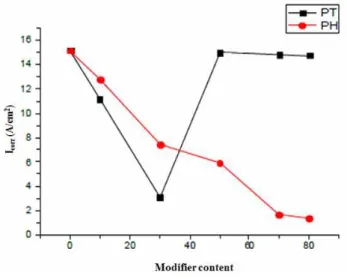
The potentiodynamic polarization test was carried out in 0.35 wt% NaCl solution to evaluate the corrosion pro- tection performance of the specimens. The potentiody- namic polarization curves of PH80 (the highest hydro- phobic property) and P0 (the lowest hydrophobic prop- erty) were shown in Fig. 13. The variations of Ecorr and Icorr of the specimens were described in Fig. 14 and Fig.
15, respectively. The polarization curve of PR816, PR976 Fig. 12 SEM images of surface morphology of PVDF coatings with HMDZ. (a) PH10, (b) PH30, (c) PH50, (d) PH70, and (e) PH80
Fig. 13 Potentiodynamic polarization curve of P0 and PH80.
Fig. 14 Ecorr variation of specimens.
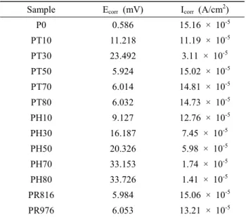
Table 6 Ecorr and Icorr of specimens
Sample Ecorr (mV) Icorr (A/cm2)
P0 0.586 15.16 × 10⁻⁵
PT10 11.218 11.19 × 10⁻⁵
PT30 23.492 3.11 × 10⁻⁵
PT50 5.924 15.02 × 10⁻⁵
PT70 6.014 14.81 × 10⁻⁵
PT80 6.032 14.73 × 10⁻⁵
PH10 9.127 12.76 × 10⁻⁵
PH30 16.187 7.45 × 10⁻⁵
PH50 20.326 5.98 × 10⁻⁵
PH70 33.153 1.74 × 10⁻⁵
PH80 33.726 1.41 × 10⁻⁵
PR816 5.984 15.06 × 10⁻⁵
PR976 6.053 13.21 × 10⁻⁵
and PH80 was shown in Fig. 16 and Ecorr and Icorr values
for all specimens were listed in Table 6.
4. Discussion
4.1. Analysis of fumed silica
4.1.1. Fourier transform infrared spectroscopy (FT-IR) In Fig. 5, a large O-H absorption peak at 3450 cm-1, indicating the hydroxyl group was shown in fumed silica without modification. After surface modification of fumed silica, the O-H absorption peak decreased and the aliphatic asymmetry absorption peak of a methyl group at 2971 cm-1 and the absorption peak of the trimethylsilyl group at 846 cm-1 increased with the increase of TMCS contents.
Therefore, it was confirmed that the hydroxyl group de-
creased and replaced by the trimethylsilyl group of TMCS.
However, it can be confirmed that new absorption peaks are generated between the regions of 2850 to 2450 cm-1 of the modified fumed silica with 50 wt% or higher con- tents of TMCS, indicating the presence of triethylammo- nium chloride during the modification process [16]. From the results of FT-IR analysis, it can be seen that the reaction of the hydroxyl group and TMCS on the surface of fumed silica increases as the content of TMCS increases.
Table 7 and Table 8 show the ratio of the FT-IR peak intensity between the methyl group, trimethylsilyl groups and hydroxyl groups when fumed silica was modified with TMCS and HMDZ, respectively.
As the contents of HMDZ increases during the mod- ification, the O-H absorption peak decreased. On the other hand, the intensity of the methyl group and the trime- thylsilyl group increases. As a result of the FT-IR analysis, the hydroxyl groups of fumed silica act as reaction cites during the modification process and consequently became fumed silica more hydrophobic.
4.1.2. X-ray photoelectron spectroscopy (XPS)
In the XPS analysis of the Si 2p spectrum, the peak at 103.5 eV (Si- O2 bond) and 102.1 eV(Si-C bond) were observed, as shown in Fig. 7, Fig. 8 and Fig. 9. in terms of contents of TMCS and HMDZ, respectively.
From the results, it was clearly demonstrated that the SiO2 peak (103.5 eV) and Si-C peak (102.1 eV) were Fig. 15 Icorr variation of specimens.
Fig. 16 Potentiodynamic polarization curve of PR816, PR976 and PH80.
Table 7 Quantitative analysis of TMCS for modified fumed silica
Methyl/hydroxyl Trimethylsilyl/hydroxyl
NS 0 0
T10 0.15827 0.23741
T30 0.17919 0.26590
T50 0.19835 0.42975
T70 0.35333 0.47333
T80 0.51145 0.49802
Table 8 Quantitative analysis of HMDZ for modified fumed silica
Methyl/hydroxyl Trimethylsilyl/hydroxyl
NS 0 0
H10 0.0507 0.11149
H30 0.2155 0.40519
H50 0.2440 0.4881
H70 0.2516 0.5226
H80 0.952 0.77419
increased with the increase of TMCS and HMDZ increase, respectively.
4.1.3. Elemental analysis (EA)
As described in Table 3 of EA analysis results, carbon contents of fumed silica surface increased with an increase of the modifier contents, indicating the increase of trime- thylsilyl groups with high carbon content instead of hy- droxyl groups. These results agreed well with FT-IR and XPS analysis results.
4.1.4. Transmission electron microscopy (TEM)
Fig. 10 shows the results of TEM observation. NS (Fumed silica, which is not treated with a modifier) is not distributed well due to its aggregation in solvents, whereas surface-treated fumed silica can be found to be well-dispersed. As a result, the use of surface-modified fumed silica to PVDF coating is considered to achieve uniform distribution in PVDF coating and hydrophobic surface properties.
4.2. Analysis of PVDF coating with hydrophobic surface-modified fumed silica
4.2.1. Scanning probe microscopy (SPM) and Water contact angle (WCA)
The surface roughness of PVDF coating increase with the increase of the modifier contents as described in Table 4 and the main cause of surface roughness increase seems caused by uniform dispersion and the increase of volume of fumed silica due to modification of TMCS and HMDZ as shown in Fig. 2 and Fig. 4.
Table. 5 shows the results of contact angle measurement according to the modifier contents. In case of PVDF coat- ing with the TMCS modifier, the water contact angle in- creased with the increase of the TMCS modifier to 30 wt%
then decreased to 88.77o. This Phenomenon seems caused by triethylammonium chloride, a kind of the water soluble hydrophilic salts. The triethylammonium chloride was formed on the fumed silica surface during the surface modification process when the TMCS more than 30 wt%
was added to fumed silica. And it provided the water affin- ity to the PVDF coating [18]. On the other hand, the water contact angle of PVDF coating with the HMDZ modifier increase with the increase of the modifier contents.
4.2.2. Field emission scanning electron microscopy (FE-SEM)
PVDF coating surface was observed by SEM as shown in Fig. 11 and Fig. 12. In case of PVDF coating with TMCS modified fumed silica, the surface of the PVDF coating with higher contents of TMCS modified fumed
silica was more porous and rough and this phenomenon was happened the PVDF coating with HMDZ modified fumed silica. This SEM observation result was agreed well to the results of scanning probe microscopy observation.
4.2.3. Potentiodynamic polarization test
Fig. 14, Fig. 15 and Table 6 show the potentiodynamic polarization test results of PVDF coatings in terms of modified fumed silica contents. From the results, Ecorr val- ues increased and the Icorr values decreased with the in- crease of HMDZ modified fume silica contents. These re- sults clearly indicated that the corrosion resistance of the PVDF coating increased with the increase of hydrophobic property by the introduction of HMDZ modified fume silica. The improvement of corrosion protection seems caused by improving the barrier property against water penetration into coating [14]. However, PVDF coating with TMCS modified fumed silica show different ten- dency from that with HMDZ modified fume silica. The Ecorr and Icorr values of PT50, PT70 and PT80 were lower than those of PT10 and PT30 and it because of the for- mation of hydrophilic triethylammonium chloride salts.
These results are in good agreement with the results of the water contact angle of PVDF coating with TMCS that water contact angle increased with the increase of the TMCS modifier to 30 wt% then decrease to 88.77o. The corrosion protection performance of PVDF coating (PR816 and PR976) with commercial fumed silica was also com- pared with PVDF coating (PH80). Consequently, Ecorr val- ue of PH80 is significantly higher than that of PR816 and PR976.
5. Conclusion
In this study, the hydrophobically surface-modified fumed silica was synthesized and added to the PVDF coating. Surface modification of fumed silica was ana- lyzed by FT-IR, XPS and EA and dispersion of modified fumed silica was observed by TEM analysis. Surface roughness and morphology of PVDF coating with modi- fied fumed silica was examined by SPM and SEM observation. Finally, corrosion protection of PVDF coat- ing with modified fumed silica was evaluated by the po- tentiodynamic polarization test. The hydrophobic property of PVDF coating increased with the increase of HMDZ modified fumed silica. On the other hand, the hydrophobic property of PVDF coating increased when TMCS modi- fied fumed silica is added to 30 wt%, then decreased with the increase of TMCS modified fumed silica because of formation of hydrophilic triethylammonium chloride salts.
Consequently, it can be concluded that the hydrophobic
surface-modified fumed silica using HMDZ is an effective additive for improving the corrosion protection perform- ance of the PVDF coatings.
Acknowledgments
This work was supported by a Research Grant of Pukyong National University (2019).
References
1. Y. Y. Yan, N. Gao, and W. Barthlott, Adv. Colloid Interfac., 169, 80 (2011).
2. W. Barthlott and C. Neinhuis, Planta, 202, 1 (1997).
3. N. A. Patankar, Langmuir, 20, 8209 (2004).
4. Y. Shi and X. Xiao, J. Disper. Sci. Technol., 37, 640 (2016).
5. R. P. S. Chakradhar, G. Prasad, P. Bera, and C. Anandan, Appl. Surf. Sci., 301, 208 (2014).
6. L. Huang, S. P. Lau, H. Y. Yang, E. S. P. Leong, S.
F. Yu, and S. Prawer, J. Phys. Chem. B, 109, 7746 (2005).
7. H. Liu, L. Feng, J. Zhai, L. Jiang, and D. Zhu, Langmuir, 20, 5659 (2004).
8. X. Feng, L. Feng, M. Jin, J. Zhai, L. Jiang, and D. Zhu, J. Am. Chem. Soc., 126, 62 (2004).
9. D. A. Seiler, Modern Fluoropolymers High Performance
Polymers for Diverse, pp. 1 - 637, John Wiley & Sons, New York (1997).
10. L. Yan, K. Wang, and L. Ye, J. Mater. Sci. Lett., 22, 1713 (2003).
11. C. Peng, S. Xing, Z. Yuan, J. Xiao, C. Wang, and J. Zeng, Appl. Surf. Sci., 259, 764 (2012).
12. Y. H. Kim, A study on the self cleaning effect by methyl silicate on PCM polyvinylidene fluoride coating, Pukyong National University (2013).
13. G. Wypych, Handbook of Fillers 4th ed., pp. 1 - 938, ChemTec Publishing, Toronto (2016).
14. A. M. A. Mohamed, A. M. Abdullah, and N. A. Younan, Arab. J. Chem., 8, 749 (2015).
15. P. Yuan, D. Yang, Z. Lin, H. He, X. Wen, L. Wang, and F. Deng, J. Non-Cryst. Solids, 352, 3762 (2006).
16. M. J. Child, M. J. Heywood, S. K. Pulton, G. A. Vicary, and G. H. Yong, J. Colloid Interf. Sci., 89, 202 (1982).
17. Adel M. A. Mohamed, Aboubakr M. Abdullah, and Nathalie A. Younan, Arab. J. Chem., 8, 749 (2015).
18. K. Sano, A. Yamada, A. Matsui, H. Tsuji, S. Hasegawa, Y. Maekawa, Effect of salt-containing filter paper attached to osmotic membrane, Desalination, 324, 34 (2013).
19. L. Peng, W. Lei, P. Yu, and Y. Luo, RSC Adv., 6, 10365 (2016).
20. D. A. Seiler, Modern fluoropolymers high performance polymers for diverse applications, pp. 1 – 637, John Wiley
& Sons, New York (1997).