JKSMRM 14:10-20(2010)
1Bio-Imaging & Signal Processing Lab, Dept. Bio/Brain Engineering, Korea Advanced Institute of Science & Technology (KAIST)
2Department of Radiology and Research Institute of Radiological Science, Yonsei University College of Medicine Received; December 7, 2009, revised; February 10, 2010, accepted; March 1, 2010
Corresponding author : Jong Chul Ye, Ph.D., Bio-Imaging & Signal Processing Lab, Dept. Bio/Brain Engineering, Korea Advanced Institute of Science & Technology (KAIST), 373-1 Guseong-dong Yuseong-gu, Daejon 305-701, Korea.
Tel. 82-42-350-4320 Fax. 82-42-350-4310 E-mail: [email protected]
High Resolution Time Resolved Contrast Enhanced MR Angiography Using k-t FOCUSS
Hong Jung1, Eung Yeop Kim2, Jong Chul Ye1
Purpose : Recently, the Recon Challenge at the 2009 ISMRM workshop on Data Sampling and Image Reconstruction at Sedona, Arizona was held to evaluate feasibility of highly accelerated acquisition of time resolved contrast enhanced MR angiography. This paper provides the step-by-step description of the winning results of k-t FOCUSS in this competition.
Materials and Methods : In previous works, we proved that k-t FOCUSS algorithm successfully solves the compressed sensing problem even for less sparse cardiac cine applications. Therefore, using k-t FOCUSS, very accurate time resolved contrast enhanced MR angiography can be reconstructed. Accelerated radial trajectory data were synthetized from X-ray cerebral angiography images and provided by the organizing committee, and radiologists double blindly evaluated each reconstruction result with respect to the ground-truth data.
Results : The reconstructed results at various acceleration factors demonstrate that each components of compressed sensing, such as sparsifying transform and incoherent sampling patterns, etc can have profound effects on the final reconstruction results.
Conclusion : From reconstructed results, we see that the compressed sensing dynamic MR imaging algorithm, k-t FOCUSS enables high resolution time resolved contrast enhanced MR angiography.
Index words :Time resolved contrast enhanced MR angiography Compressed sensing
k-t FOCUSS
Karhunen-Loeve Transform Principal component analysis
Introduction
Angiography is an imaging technique to depict structures of vessels and blood flow in arteries and veins. The main interest of this technique is to find the disorder of blood vessels such as stenosis, occlusion, or aneurysms.
X-ray angiography is a standard tool for blood vessel diagnosis. For X-ray angiography, contrast agent must be injected into the patient using a catheter. Then, to obtain blood vessel images, digital subtraction angiography (DSA) is generally used which subtracts a subsequently acquired image without contrast agent from images with contrast agent. However, the procedure is quite invasive.
In order to resolve these issues, there have been intensive researches to exploit other imaging modalities such as CT or MRI in angiography. Currently, CT angiography (CTA) using iodine contrast agent is most widely used as a replacement of the conventional X-ray angiography (1). However, CTA is considered harmful for routine use due to radiation risk (2). In contrast, MR angiography (MRA) is safer (3). Contrast enhanced MRA (CE-MRA) uses gadolinium as a contrast agent.
Gadolinium reduces T1 so that the signal intensity of blood vessel filled with gadolinium becomes high.
However, it is generally accepted that the resolution of CE-MRA is poorer than that of CTA due to slow acquisition time. Since MR acquisition is based on Fourier transform, the number of measured k-space data should satisfy Nyquist sampling limit to avoid aliasing artifacts, which usually results in trade-off between spatial and temporal resolution in MRA.
Recently, several novel approaches have been developed to reduce scanning time while preserving image qualities. For example, parallel imaging methods such as sensitivity encoding (SENSE) (4), simultaneous acquisition of spatial harmonics (SMASH) (5), generalized autocalibtrating partially parallel acquisitions (GRAPPA) (6) accelerate data acquisition time by obtaining a subset of k-space data and resolve aliasing artifacts by exploiting the diversity of coil sensitivity. However, it was reported in (7, 8) that an acceptable image quality can be generated at only limited acceleration factor due to the amplification of noise.
Our approach is different from conventional algorithms thanks to the use of “compressed sensing”
theory (9, 10). According to compressed sensing theory, perfect reconstruction is possible even from sampling rates dramatically smaller than the Nyquist sampling limit by solving an l1minimization problem, as long as the non-zero spectral signal is sparse and the samples are obtained with an incoherent basis (10). Therefore, compressed sensing may be one of the most suitable approaches for CE-MRA, since the temporal variation of CE-MRA is usually very sparse in spatio-temporal domain. Recently, we have developed compressed sensing based dynamic MR imaging algorithm called k- t FOCUSS (11, 12). k-t FOCUSS has been successfully applied to cardiac cine imaging. Hence, applying k-t FOCUSS to CE-MRA, great performance can be expected thanks to its spatio-temporal sparsity.
Furthermore, by incorporating k-t FOCUSS in radial trajectory using golden trajectory (13), the advantage of radial trajectory can be exploited as well. In order to make k-t FOCUSS more effective, the temporal basis should be chosen judiciously such that the transformed signal can be effectively sparsified. We found that principal component analysis (PCA) provides a suitable basis. Experimental results using the data provided by Recon challenge at 2009 ISMRM workshop for Data Sampling and Image Reconstruction show that an accurate reconstruction can be achieved from very sparse measurements.
Even though the results presented in this communication is based on simulated MRA data from X-ray cerebral angiography, the insight we obtained from this exercise may provide a promising direction in CE-MRA.
Methods
k-t FOCUSS has been developed for high spatio- temporal resolution dynamic MR imaging such as cardiac cine imaging (11, 12). The basic concept for k-t FOCUSS comes from compressed sensing theory which tells us that the accurate reconstruction is possible using only limited number of measurements if the unknown image can be sparsely represented. Here, the essential requirement for the success of compressed sensing is the “sparsity” of images. Time resolved CE- MRA is therefore suitable for compressed sensing
framework since the difference between adjacent frames is only restricted inside of vessels which are relatively stationary and sparse. Furthermore, the temporal variation of contrast agent is often slowly varying, which can be effectively sparsified in appropriate basis. According to compressed sensing theory, those very sparse signals can be very accurately reconstructed by solving a computationally feasible l1 minimization problem as follows:
min‖ρ‖1
subject to ‖υ- FΨρ‖2≤ ε, [1]
where ρ, Ψ, F, and υrepresent a vector stacked by unknown sparse signal, temporal sparsifying transform, Fourier transform from image space to k-space, and a vector stacked by k-t measurements, respectively. Here ε, denots the noise level. In order to solve Eq. [1], k-t FOCUSS finds:
ρn+1= Wnqn, [2]
by iteratively solving re-weighted l2 minimization problem as follows:
min‖qn‖2
subject to ‖υ- FΨWnqn‖2≤ ε, [3]
where Wl+1is updated as:
In (11), it was proved that this algorithm solves l1 minimization problem by setting p = 0.5. If we set 0.5<p<1, Eq. [3] will solve lq minimization for q<1, which guarantees a sparser global minimization.
However, since lq (q<1) is not a convex minimization, the solution can be fallen to local minimization. The k-t FOCUSS algorithm can be then represented as:
ρn+1=ΘnΨHFH(FΨΘnΨHFH+λI)-1υ, [5]
where Θn=WnWnH and λ is a regularization parameter. If we increase λ, Eq. [5] obtains sparser solution but the data fidelity term in Eq. [3] becomes less important. Usually, λ�1 provides good image qualities.
Note that there exist several options to be optimized in k-t FOCUSS. For example, the specific choice of sparsifying transform, sampling patterns and etc. These issues will be discussed in detail in the sequel.
Temporal Sparsifying Transform
As mentioned in previous section, the “sparsity” of unknown signal is an essential condition for compressed sensing reconstruction. In (11, 12), Fourier transform (FT) along temporal direction is used to sparsify cardiac cine images. FT tends to sparsify a signal especially when signal shows sinusoidal pattern.
Therefore, when the object has periodic motion (for example moving heart), temporal FT can effectively sparsify images.
However, even if the signal does not have an obvious periodic pattern, the Fourier spectrum is mostly
│ρn+1(1)│p 0 … 0 Wn+1= 0 │ρn+1(2)│p… 0 ,
,1/2≤p≤1. [4]
� � � �
0 0 …│ρn+1(N)│p
�
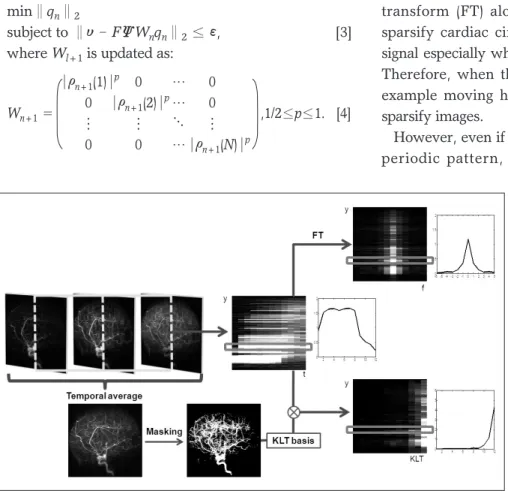
Fig. 1. Time resolved CE-MRA can be spasified using FT or KLT. Unlike FT, KLT is data dependent transform so that KLT bases should be obtained from given data set. The proposed method first applied k-t FOCUSS with temporal FT for initial reconstruction. Then, by threshold- ing the temporal averaged image, a mask is obtained and KLT bases are estimated from the temporal variation at the mask location. After KLT, the coefficients are usually very sparse.
focused at the low frequency when the signal varies slowly. Time resolved CE-MRA often has such smooth temporal variation so that FT along temporal direction works well as a sparsifying transform. To see the sparsity in Fourier spectrum, x-f image and f-axis plot at one x-point are illustrated with original x-t image and temporal variation at the same point in Figure 1. The majority of energy is concentrated at a few low frequencies since the signals smoothly vary.
Basically, k-t FOCUSS is based on compressed sensing and the sparsifying transform Ψ does not need to be constrained to FT. If there are other bases to represent images more sparsely, those bases will be more effective for k-t FOCUSS reconstruction. Based on this idea, we already used principal component analysis (PCA) to find the most sparsifying transform for functional MRI (11). The resultant transform is often called Karhunen-Loeve transform (KLT) (14). KLT is well-known as an optimal energy compaction transform for signals (14). Hence, for non-periodic signal such as time resolved CE-MRA, KLT can be a more suitable sparsifying transform than FT.
Unlike the FT, KLT is a data dependent transform.
More specifically, let σkdenote a random vector spanning time series from t1to tN.
σk= [σ(k,t1),σ(k,t2),…, σ(k,tN)]T [6]
In general, the covariance matrix C of σk can be expanded as follows:
C = E[σkσkH]= γlΨlΨlH, [7]
where {γl}N
l=1 and {Ψl}N
l=1 are the eigenvalues and the corresponding orthonormal eigenvectors of C (14).
Then, the original signal σk can be represented as follows (14):
σk= ρlΨl, [8]
where
ρl =<σk ,Ψl>. [9]
The eigenvectors {Ψl}N
l=1 and coefficients {ρl}N
l=1
correspond to the sparsifying transform Ψ and unknown sparse signal ρin Eq. [1], respectively.
The KLT provides a separation of the randomness and the time variation in the signal σk . In particular, the randomness is summarized in the sequence {ρl}N
l=1
while the time variation in the process is embodied in the deterministic functions {Ψl}N
l=1 (14). Therefore, if each pixel of CE-MRA has similar behavior along temporal direction, we can represent the temporally varying images very sparsely with a small amount of
∑N l=1
∑N l=1
b a
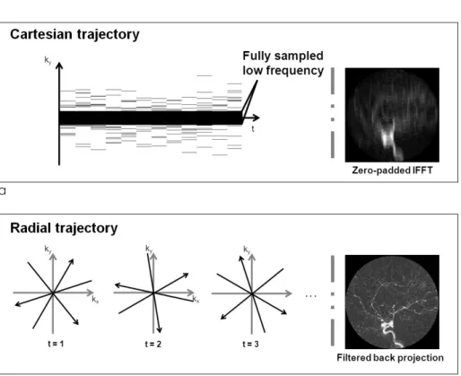
Fig. 2. Randomly sampled Cartesian and radial trajectories are illustrated with reconstructed images using conventional methods in (a) and (b), respectively.
randomness.
However, estimating KLT bases is a very underdetermined problem when the data are highly accelerated. Dealing with this problem, we approximate KLT bases using only a partial data set.
For example, in the Cartesian trajectory, as shown in Figure 2 (a), the fully sampled low frequency k-t data can be used to estimate the covariance matrix C. More specifically, let V be a fully sampled k-t data set in low frequency region:
where M and N are the total number of fully sampled low frequency k-data and the total number of time frames, respectively. Then, the covariance matrix C is obtained by:
C = VVH. [11]
Finally, the KLT bases {Ψl}N
l=1 can be estimated using eigenvector decomposition of C as in Eq. [7].
Here, it is important to note that even though KLT bases are obtained from low spatial resolution images, the temporal changes are not smoothed at all because the resultant basis is complete in CN and we can represent any temporal variation in CN with linear combination of KLT bases. Therefore, the only concern about the approximated KLT bases is if the unknown signal can be represented with sparse coefficients ρ. We confirmed that the resultant coefficients are sparse enough in the following experiments. This is one of the main differences from partially separable function (PSF) approach (15), where only l significant principle components are used for temporal transform by assuming that the rank of the unknown x-t images is l.
However, in real cases, it is hard to know the rank of the unknown x-t images a priori. In contrast, in our approach, the bases are complete and the sparse non- zero coefficients are obtained using l minimization.
In radial trajectory, since we do not have fully sampled low frequency measurements on the same coordinates along time, a novel method should be considered. In this paper, initial dynamic images are
reconstructed with k-t FOCUSS using FT. Then, we set the mask M that may correspond to the vessel area.
The mask M is determined by a simple thresholding:
M (x)=
{
1,0, if│σotherwise,^(x)│≥Υ [12]where σ^ and Υ represent temporal average of initial k-t FOCUSS results and specified thresholding value, respectively. Temporally varying signals on the non- zero mask are then extracted to estimate the temporal covariance matrix. Then, KLT bases are obtained by eigen-decomposition as described above. Figure 1 briefly summarizes these steps and demonstrates the sparse signals after KLT. Through this process, the temporal variation due to streaking artifact patterns can be excluded in determining KLT bases.
Incoherent Sampling
In (11, 12), we achieved successful performance of k-t FOCUSS in Cartesian trajectory in cardiac cine imaging which is usually less sparse than MRA. Meanwhile, several high performance algorithms, such as highly- constrained back-projection (HYPR) (16) or iterative HYPR (I-HYPR) (17), use radial trajectory for MRA.
Therefore, one may wonder which trajectory is more suitable for MRA. Since both trajectories have incoherent sampling basis with respect to image space, compressed sensing framework works for both cases.
Figure 2 (a) and (b) show the artifact patterns in Cartesian and radial trajectories, respectively. The artifacts are spread over whole image space like noise pattern and this proves the incoherency of sampling basis in both trajectories.
However, due to differences in Cartesian and radial trajectories, there exists pros and cons for each method.
For example, in radial trajectory, spatial resolution is mainly determined by imaging field of view (FOV) and there is smaller trade off between spatial resolution and number of views in contrast to the Cartesian trajectory.
Furthermore, due to the oversampled k-space region, radial trajectory is more robust to motion artifacts (18) and more accurate contrast reconstruction is possible.
Moreover, using golden ratio trajectories (13), we can distribute sampling trajectories without overlap on different time points. More specifically, by specifying the angle increment between consecutive views with υ(k1,t1) υ(k2,t1) … υ(kM,t1)
V= υ(k1,t2) υ(k2,t2) … υ(kM,t2)
, [10]
� � � �
υ(k1,tN)υ(k2,tN) … υ(kM,tN)
�
111.25。, the sampling incoherency can be preserved for arbitrary choices of the number of views and time frames for already acquired data set. From a computational complexity point of view, Cartesian trajectory is, however, more advantageous than radial trajectory. Specifically, the reconstruction can be done using fast Fourier transform (FFT), whereas radial trajectory requires computationally expensive projection/back-projection or gridding. Another issue comes from using KLT. As already explained in the perviovs section, radial trajectory require initial reconstruction to obtain KLT bases, whereas Cartesian trajectory does not need the initial reconstruction since fully sampled low frequency k-t data can be used for KLT basis estimation.
Up-Sampling
Increasing imaging FOV makes the resultant image sparser. According to Fourier slice theorem, each read- out data in radial trajectory corresponds to the Fourier transform of a sinogram obtained from projection of an image. Therefore, inverse Fourier transform of one read-out corresponds to the sinogram of original image.
Hence, just zero-padding at both ends of each sinogram with arbitrary size, imaging FOV can be extended without any distortion of original image contents. The zero-padding scheme is a quite common technique in signogram-based reconstruction (19). It is usually employed for correct implementation of discretized filtered back projection. However, in our approach, we employed this zero-padding scheme for sparser representation of the unknown images.
Actually, when the number of views is close to Nyquist sampling criteria, this step is not necessary to avoid aliasing artifacts. However, if the number of views is very limited so that the empty k-space is estimated with small number of measurements, estimation error of k-space data can result in aliasing artifact in image domain especially when the size of FOV is similar to the size of image contents. In this case, employing up-sampling scheme mentioned above, image quality can be greatly improved without serious aliasing artifacts, as will be demonstrated later.
Materials
The accelerated simulated data were provided at the
“Recon Challenge” of 2009 ISMRM workshop on Data Sampling and Image Reconstruction (http://www.
ismrm.org/workshops/Data_09/recon.htm). Data were simulated from X-ray cerebral angiography. X-ray data were collected 3 frames per second, with 2048 in-plane resolution, for a total of 8 seconds (24 collected frames) which span wash-in to wash out of injected bolus. The images were blurred to 512 resolution, and linearly interpolated in time between frames to create a total of 512 time frames. Coil sensitivity maps obtained from an axial slice through a water phantom using an 8 channel head coil were superimposed on the image to create 8 coil images. Independent noise was added to each channel. From each temporal image, one read-out was obtained with size of 512 in radial trajectory so that the given total number of simulated k-data was 512×512. Here, the time interval between each interpolated time frame corresponds to TR in real MR acquisition. Then, reconstruction was performed at 12 time points corresponding to the 39, 79, 118, 157, 197, 236, 275, 314, 354, 393, 432, 472 nd time frames.
In radial acquisition, the view order was based on the golden ratio whose angle increment between consecutive views is 111.25。(13). In this scheme, there was no overlap of trajectories in 512 views and we could choose arbitrary number of views to reconstruct each time frame since any consecutive views are broadly distributed over k-space as described in (13). In this paper, the experiments were conducted at 12- and 51.2-fold acceleration. At 12-fold acceleration, all of the given 512 views were used for reconstruction.
Specifically, k-space data at different time were aggregated with 39 or 40 sized windows whose centers were placed at target time frames, such as the 39, 79, 118, 157, 197, 236, 275, 314, 354, 393, 432, 472 nd. The window size 39 or 40 was determined by a time distance between current target frame and previous target frame. For 51.2-fold acceleration, we simply used 10 views for each time frame. From these data sets, the reconstruction was performed for each coil using k-t FOCUSS with various compressed sensing parameters.
For up-sampling, we generated 1024 sized read-out by padding zeros at both ends of each 512 sized sinogram and the up-sampling factor was 2. For comparison of the performance in different trajectories, we additionally acquired randomly sampled data in Cartesian trajectory. Here, the acceleration factor was
12. Final results were obtained by root sum of squares of 8-coil images. For the quantitative evaluation of each result, the interpolated X-ray images corresponding to 39, 79, 118, 157, 197, 236, 275, 314, 354, 393, 432, 472 nd time frames are multiplied by coil sensitivity maps, and the root-square sum of squared images of 8-coils are used as a ground truth. Our winning result at the Recon Challenge was the result reconstructed using up- sampling and KLT at 12-fold acceleration factor.
Experimental Results
For the effect of different parameters, we illustrated radial k-t FOCUSS results using FT with no up- sampling, FT with up-sampling, and KLT with up- sampling together with ground truth in Figure 3. For fair comparison, the pixel values were equally scaled with fixed minimum and maximum values for different methods. Here, the acceleration factor was 12. When there was no up-sampling, the overall image quality was poor with streaking and aliasing artifacts as indicated by arrows. In contrast, after up-sampling, FT and KLT results illustrate no such artifacts. The magnified images help to see the detailed structures and contrast changes around vessels. It is observed that KLT results have the finest vessel structures.
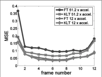
For quantitative comparison of FT and KLT methods, we calculated mean square errors (MSE) at 51.2 and 12-
fold acceleration factors in Figure 4. When acceleration factor is low, both methods show comparable MSE.
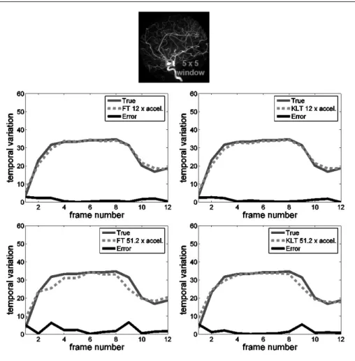
However, when acceleration factor is high, the improvement in KLT result is significant. For further analysis about temporal resolution, temporal variations of averaged pixel values within specified 5×5 window were plotted together with true values and corresponding errors in Figure 5 for 12 and 51.2-fold accelerations. Similar to MSE results, when the acceleration factor is low, both results correctly follow
Fig. 3. Two different time frames representing spread of bolus are illustrated to compare the perfor- mance of FT without up-sampling, FT with up-sampling, and KLT with up-sampling. The acceleration factor was 12 and up-sampling factor was 2. Without up-sampling, streaking and aliasing artifacts are visible as indicated by arrows. Up-sampling improves the image quality. Using KLT, further improved images can be reconstructed. KLT results show the finest vessel structure in magnified images.
Fig. 4. Mean square error (MSE) was plotted for FT and KLT at 51.2 and 12-fold acceleration. KLT shows significantly reduced MSE especially at high acceleration compared to FT.
the true values, whereas at high acceleration KLT result shows better performance.
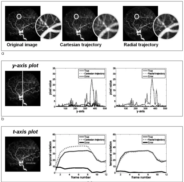
In order to compare the performance in Cartesian and radial trajectories, we have conducted comparative studies in Figure 6. Here, the acceleration factor was 12 and KLT was used as a sparsifying transform for both trajectories. Figure 6 (a) shows one time frame. The images of both trajectories look nice without aliasing or streaking artifacts but in magnified version, it is observed that radial trajectory has finer vessel structures. Figure 6 (b) and (c) again confirm that radial results are better than Cartesian results by plotting spatial and temporal variation.
Finally, Table 1 briefly summarizes k-t FOCUSS using FT and KLT in Cartesian and radial trajectory in terms of reconstruction time and MSE. Reconstruction time was measured for each coil by CPU time on Xeon 3 GHz Linux platform with 4 GB RAM using Matlab 7.0.4. Then, MSE was calculated for each time frame.
Here, the acceleration factor was 12 and this sampling ratio was enough to directly estimate KLT bases in
Cartesian trajectory. Hence, the reconstruction time was similar in using FT and KLT in Cartesian trajectory. Similar to the radial trajectory, KLT result with Cartesian sampling shows smaller MSE than FT result. Next, temporal FT without up-sampling in radial trajectory shows very poor performance. By using up- sampling by factor of 2, the MSE value was significantly reduced. If KLT is used for temporal transform, the results can be further improved. Note
Fig. 5. Temporal variation of averaged pixel values within the specified window is plotted for FT and KLT at 12 and 51.2-fold accelerations. At 12-fold accelera- tion, both methods show accurate time variations. However, at 51.2- fold acceleration, only KLT method correctly follows true temporal variation.
Table 1. Comparison of various versions of k-t FOCUSS in terms of reconstruction time and MSE for each coil. The last line shows the winning combination at ISMRM workshop
k-t FOCUSS Parameters
Sampling Sparsifying Up- Recon. Time MSE Trajectory Transform Sampling
Cartesian FT no 01 min 22 sec 1.9132 Cartesian KLT no 01 min 24 sec 1.7897
Radial FT no 03 min 37 sec 4.3863
Radial FT 2-fold 18 min 40 sec 0.8137 Radial KLT 2-fold 37 min 38 sec 0.7470
that the problem of up-sampling is longer time for reconstruction. This is due to large memory requirement. Furthermore, since KLT basis should be estimated after initial reconstruction, KLT in radial trajectory requires additional computational time.
Conclusion
This paper described the k-t FOCUSS algorithm that won the Recon Challenge at 2009 ISMRM Data Sampling and Image Reconstruction workshop. Since
MRA is usually composed of very sparse vessel structures, it is a very suitable application of compressed sensing. In this paper, we proved that k-t FOCUSS that has been successfully applied to cardiac cine imaging is also effective in time resolved CE-MRA.
Several sparsifying transforms and various options have been compared. Through various experiments, we confirmed that KLT with radial trajectory with up- sampling outperforms other combinations of sparsifying transforms, sampling patterns, etc.
a
b
c
Fig. 6. k-t FOCUSS with KLT was implemented in Cartesian and radial trajectories at 12-fold acceleration and both resultant images are compared in (a). Both results look similar but in magnified version radial trajectory shows finer vessel structures. Similarly, in y-axis and t-axis plot in (b) and (c), radial trajectory shows more accurate results.
Acknowledgement
The authors would like to thank Prof. Jim Pipe and Nick Zwart in Barrow Neurological Institute in Arizona, USA for providing the data.
References
1.B. Urban, L. Ratner, and E. Fishman, Three-dimensional Volume-rendered CT Angiography of the Renal Arteries and Veins: Normal Anatomy, Variants, and Clinical Application 1, Radiographics, 2001;21(2):373-386
2.P. Zanzonico, L. Rothenberg, and H. Strauss, Radiation Exposure of Computed Tomography and Direct Intracoronary Angiography Risk has its Reward, Journal of the American College of Cardiology, 2006;47(9):1846-1849
3.V. S. Lee, Cardiovascular MRI: Physical principles to practical protocols. Philadelpia: Lippincott Williams & Wilkins, 2006.
4.K. P. Pruessmann, M. Weigher, M. B. Scheidegger, and P.
Boesiger, SENSE: Sensitivity encoding for fast MRI, Magn.
Reson. Med, 1999;42(5):952-962
5.D. K. Sodickwon and W. J. Manning, Simultaneous acquisition of spatial harmonics (SMASH): fast imaging with radiofrequency coil arrays, Magn. Reson. Med, 1997;38(4)591- 603.
6.M. A. Griswold, P. M. Jakob, R. M. Heidemann, M. Nittka, V. Jellus, J. Wang, B. Kiefer, and A. Haase, Generalized autocalibrating partially parallel acquisitions (GRAPPA), Magn. Reson. Med, 2002;47(6):1202-1210
7.D. Sodickson, C. McKenzie, W. Li, S. Wolff, W. Manning, and R. Edelman, “Contrast-enhanced 3D MR Angiography with Simultaneous Acquisition of Spatial Harmonics: A Pilot Study 1, Radiology, 2000;217(1):284-289
8.G. Wilson, R. Hoogeveen, W. Willinek, R. Muthupillai, and J.
Maki, “Parallel Imaging in MR Angiography,” Topics in Magnetic Resonance Imaging, 2004;15(3):169-185.
9.M. Lustig, D. Donoho, and J. Pauly, Sparse MRI: The application of compressed sensing for rapid MR imaging, Magn. Reson. Med, 2007;58(6):1182-1195
10.D. L. Donoho, Compressed sensing, IEEE Trans. on Information Theory, 2006;52(5):1289-1306
11.H. Jung, J. C. Ye, and E. Y. Kim, Improved k-t BLAST and k-t SENSE using FOCUSS, Physics in Medicine and Biology, 2007;52(11)3201-3226
12.H. Jung, K. Sung, K. S. Nayak, E. Y. Kim, and J. C. Ye, k-t FOCUSS: a general compressed sensing framework for high resolution dynamic MRI, Magn. Reson. Med, 2009;61:103-116 13.S. Winkelmann, T. Schaeffter, T. Koehler, H. Eggers, and O.
Doessel, An optimal radial profile order based on the Golden Ratio for time-resolved MRI, IEEE Transactions on Medical Imaging, 2007;26(1):68-76
14.H. V. Poor, An Introduction of Signal Detection and Estimation, 2nd ed. New York: Springer-Verlag, 1994.
15.Z. Liang, Spatiotemporal Imaging with Partially Separable Functions, in 4th IEEE International Symposium on Biomedical Imaging: From Nano to Macro, 2007, p. 988-991 16.C. Mistretta, O. Wieben, J. Velikina, W. Block, J. Perry, Y.
Wu, K. Johnson, and Y. Wu, Highly constrained backprojec- tion for time-resolved MRI, Magn. Reson. Med, 2006;55(1)30- 40
17.R. O’Halloran, Z. Wen, J. Holmes, and S. Fain, Iterative projection reconstruction of time-resolved images using highly-constrained back-proejction (HYPR), Magn. Reson.
Med, 2008;59(1):132-139
18.J. Wild, M. Paley, L. Kasuboski, A. Swift, S. Fichele, N.
Woodhouse, P. Griffiths, and E. van Beek, Dynamic radial projection MRI of inhaled hyperpolarized 3 He gas, Magn.
Reson. Med, 2003;49(6):991-997
19.Z. P. Liang and P. C. Lauterbur, Principles of magnetic resonance imaging: A signal processing perspective, New York: IEEE press, 2000.
통신저자 : 예종철, (305-701) 대전광역시 유성구 구성동 373-1
한국과학기술원 바이오및뇌공학과 바이오 영상 및 신호처리 연구실
Tel. 82-42-350-4320 Fax. 82-42-350-4310 E-mail: [email protected]
k-t FOCUSS 알고리듬을 이용한 고분해능 4-D MR 혈관 조영 영상 기법
1한국과학기술원 바이오및뇌공학과 바이오 영상 및 신호처리 연구실
2연세대학교 의과대학 영상의학과
정 홍1∙김응엽2∙예종철1
목적: 최근, 미국 애리조나 세도나에서 열린 국제자기공명학회 (ISMRM) 주관의 2009년 데이터 샘플링과 영상 복 원에 관한 워크샵에서 자기공명영상 복원 대회가 열렸다. 이 대회는 time resolved contrast enhanced MR angiography 에 대한 고속 촬영의 실제 활용 가능성을 평가하기 위한 것이었다. 본 논문은 이 대회의 우승 결과를 얻은 k-t FOCUSS 알고리듬을 단계별로 자세히 묘사하도록 한다.
대상 및 방법: 본 그룹은 앞선 연구에서 비교적 덜 스파스한 심장 영상에 대해 k-t FOCUSS 알고리듬이 성공적으로 압축센싱 문제를 풀수 있음을 증명했다. 따라서 k-t FOCUSS 알고리듬을 time resolved contrast enhanced MR angiography 에 적용함으로써, 매우 정확한 영상 복원이 가능할 것이다. 영상 복원을 위해 X-ray 대뇌 혈관조 영 영상으로부터 구성된 다운 샘플링된 데이터가 대회 주최측으로부터 공통으로 제시되었고, 방사선과 의사들이 각 복원된 영상에 대한 사전 정보 없이, 원래 영상과 복원된 결과를 비교함으로써, 영상의 질을 평가하였다.
결과: 다양한 다운샘플링에 대해 얻어진 결과들은 영상의 스파스 변환이나 샘플링 형태와 같은 압축센싱의 중요한 요 소들에 의해 크게 영향을 받는다는 것을 보여주었다.
결론: 복원된 결과로부터, 압축센싱 동적자기공명영상 기법인 k-t FOCUSS 가 고해상도의 time resolved contrast enhanced MR angiography 를 가능하게 할 수 있음을 확인하였다.
대한자기공명의과학회지 14:10-20(2010)