Development of Hardware for the Architecture of A Remote Vital Sign Monitor
Jang Dong-Wook
1, Jang Sung-Whan
2, Jeong Byoung-Jo
2*and Hyun-Seob Cho
31Computer Engineering, Mississippi State University,
2Dept. of Electrical Engineering, Wonkwang University,
3Dept. of Digital Broadcast Engineering, Chungwoon University
무선 체온 모니터기 아키텍처 하드웨어 개발
장동욱
1, 장성환
2, 정병조
2*, 조현섭
31미시시피 주립대학교 컴퓨터공학과, 2원광대학교 전기공학과,
3청운대학교 디지털방송공학과
Abstract A Remote Vital Sign Monitor is an in-home healthcare system designed to wirelessly monitor core-body temperature. The Remote Vital Sign Monitor provides accuracy and features which are comparable to hospital equipment while minimizing cost with ease-of-use. It has two parts, a bandage and a monitor. The bandage and the monitor both use the Chipcon2430(CC2430) which contains an integrated 2.4GHz Direct Sequence Spread Spectrum radio. The CC2430 allows Remote Vital Sign Monitor to operate at over a 100-foot indoor radius. A simple user interface allows the user to set an upper temperature and a lower temperature that is monitored with respect to the core-body temperature. If the core-body temperature exceeds the one of two defined temperatures, the alarm will sound. The alarm is powered by a low-voltage audio amplifier circuit which is connected to a speaker. In order to accurately calculate the core-body temperature, the Remote Vital Sign Monitor must utilize an accurate temperature sensing device. The thermistor selected from GE Sensing satisfies the need for a sensitive and accurate temperature reading. The LCD monitor has a screen size that measures 64.5mm long by 16.4mm wide and also contains back light, and this should allow the user to clearly view the monitor from at least 3 feet away in both light and dark situations.
요 약 무선 체온 모니터기는 무선으로 체온을 모니터 하기 위해 설계된 건강관리 시스템이다. 무선 체온 모니터기
는 낮은 가격과 손쉬운 사용방법으로 병원 장치와 비교할만한 정확도와 몇몇 특성들을 제공한다. 무선 체온 모니터기 는 밴드 파트와 모니터 파트로 구성되어 있다. 밴드 파트와 모니터 파트 모두 2.4GHz 직접 시퀀스 확산 스펙트럼 라 디오가 내장되어 있는 칩콘2430, 일명 CC2430라는 마이크로 칩으로 사용한다. 이 CC2430은 무선 체온 모니터기가 집안 100피트 반경까지 상호 작동할 수 있게 해준다. 간단한 사용자 환경은 사용자로 하여금 손쉽게 고온과 저온의 한계점을 세팅할 수 있게 되어있다. 만약 사용자의 체온이 고온과 저온의 한계점을 넘어섰을 때 알람이 울리게 되어 있다. 알람은 저전압 오디오 증폭기와 스피커에 연결되어 작동되게 되어있다. 정확한 체온을 계산하기 위해 무선 체 온 모니터기는 반드시 정확한 온도 검출장치를 사용해야만 한다. GE Sensing에서 선택된 서미스터는 온도 측정의 예 민함과 정확함을 모두 만족시킨다. LCD 화면은 길이 64.5mm 폭 16.4mm의 백라이트 기능을 가추고 있으며 이 기능 은 사용자가 어두운 환경이나 밝은 환경에서도 적어도 3피트 거리에서 화면을 모니터 할 수 있게 해준다.
Key Words : Remote Vital Sign Monitor, Fourier's Law, Steinhart-hart equation
This paper was supported by research fund of Wonkwang University in 2009.
*Corresponding Author : Jeong Byoung-Jo([email protected])
Received June 7, 2010 Revised June 29, 2010 Accepted July 6, 2010
1. Introduction
People has recognized the significance of core-body temperature as a measure of good health for centuries.
Although a correlation between body temperature and health was clearly recognized, accurately measuring the body temperature was not possible in the old age. Sir Thomas Allbutt is attributed with inventing the first widely improved clinical thermometer in 1866 which touted a much shorter length and measurement time. This method of obtaining temperature was virtually unchanged until the 1990's when digital thermometers were developed. Consumers are now accustomed to variations on the standard digital thermometer such as tympanic and temporal scanning thermometers. These devices offer a wide range of conveniences and accuracy. A Remote Vital Sign Monitor will be a hybrid of existing thermometers because it will provide the convenience of the temporal scanner with the accuracy of the digital thermometer while having its own unique constrains. The Remote Vital Sign Monitor is an in-home system designed to wirelessly monitor vital signs. The initial system offers a hands-free method for continuously monitoring the core-body temperature of an individual by using a novel type of digital thermometer. A temporal artery thermometer, which is similar to a temporal scanning thermometer, is used to obtain an accurate core-body temperature from the temporal artery.
2. Body Paragraph
2.1 System Overview
The Remote Vital Sign Monitor utilized two separate devices: a bandage and a monitor. Each device contains an identical micro controller which contains an integrated radio for wireless communication. The bandage uses temperature sensing devices that are placed over the temporal artery in order to measure core-body temperature. An Analog to Digital Converter(ADC) located in the micro controller is used to monitor the temperature sensing devices. The micro controller located at the monitor receives the ADC measurements from the bandage and then uses an algorithm to calculate the
core-body temperature of a patient. An alarm system is used at the monitor to alert users when a core-body temperature exceeds the user-defined limits. Figure 1 is a diagram of the basic functionality of the Remote Vital Sign Monitor.
[Fig. 1] System Diagram
2.2 Fourier's Law of Heat Conduction
The Remote Vital Sign Monitor's calculation of core-body temperature is based on the theory of Fourier's Law of Heat Conduction which describes the heat transfer in a system due to a temperature differential. Heat transfer in a system operates much like an electric circuit; when a difference in potential energy exists across a medium, energy is transferred from the higher potential to the lower potential until the two potentials reach equilibrium.Researchers from the University of Calgary havers rive of form of Fourier's Law which is specific to a particular bandage topology and used as an example when the Remote Vital Sign Monitor is designed. Figure 2 shows the construct which was first developed by the University of Calgary [1].
[Fig. 2] University of Calgary's Bandage
The Remote Vital Sign Monitor's bandage is designed to reduce the effects of heat loss and is crucial to obtaining the most accurate temperature measurements.
The condensed form of Fourier's Law, shown in Equation (1), makes several assumptions about the heat transfer in the bandage system. The equation assumes that all of the heat flux radiated from the temporal artery is absorbed by the bandage. If the bandage did not absorb all of the heat flux, heat loss in the system would have to be considered.
Heat loss comes in the form of evaporation due to sweating, convection due to air movement, and heat transfer to other sources in the environment.
(
s b)
stissue bandage
c T T T
h
T
≅
h− +
(1)
where
is the core-body temperature in degrees Fahrenheit,
is the temperature of the skin in degrees Fahrenheit,
is the ambient temperature inside the bandage in degrees Fahrenheit,
is the thermal conductivity of the bandage, and
is the thermal conductivity of the skin [1]. There are two key components of the bandage which allow heat loss to be ignored: the bandage package and the thermal insulation.The bandage package encloses the skin and prevents air from flowing over the skin. As a result, heat loss due to convection is prevented. Without convection, evaporation is impossible and heat loss due to evaporation can be ignored. The thermal insulation, which is assumed to be a perfect insulator, forces all of the heat flux leaving the temporal artery to be absorbed by the temperature sensing devices. Since the temperature sensing devices absorb all of the heat flux emitted from the temporal artery, heat loss due to external sources can therefore be ignored. If the heat losses due to environmental factors were not ignored, the Remote Vital Sign Monitor would not be able to calculate core-body temperature in any situation [1].
2.3 Flex PCB
The flexible PCB plays an integral role in enabling accurate temperature measurements. The flexibility of the PCB allows the temperature sensing devices to have maximum skin contact. By maximizing surface area in contact with the skin, the amount of heat flux absorbed
by the temperature sensing devices is increased. In addition, the flex PCB allows the bandage to conform to the varying sizes of users’ temples. However, because of economical constraints, a rigid PCB had to be used. Tests show that the temperature accuracy is not affected by the rigidity of the PCB.
2.4 Thermal Insulation
Thermal insulation is a major factor in obtaining accurate temperature measurements. The material selected should be safe to use. Some safety concerns of thermal insulators can arise if they are hydrophilic or desiccants.
These types of materials dry out the user's skin. The material chosen as the insulator for the bandage needs to be a well known thermal insulator. The Remote Vital Sign Monitor will use a thin rubber pad for insulation.
One side of the material has a layer of tape which will assist in creating good contact with the surface during packaging.
2.5 Thermistor Hardware
Thermistors are categorized into negative temperature coefficient(NTC) and positive temperature coefficient(PTC) varieties. NTCs have a decrease in resistance as the temperature increases while PTCs have an increase in resistance as the temperature increases.
Another defining characteristic of thermistors is their stastic o. Stastic o is a measurement of the predictastic o in a thermistor's temperature-resistance curve over a set of temperatures. PTC thermistors have erratic spikes in their temperature-resistance curves and can even revert back to NTC-icke characteristics. NTC thermistors are not ncrgued with stastic o proavems and as a result are the most widelo in indu asy[2]. The Remote Vital Sign Monitor uses the NHQ504B435RreNTC thermistor from GE Sspikes. The in the is rated at 500k at 77°F. The non-linearity of the temperature- resistance curve of the selected thermistor is shown if Figure 3.
[Fig. 3] Thermistor Modeled Using MATLAB
By using the Steinhart-Hart equation, the temperature of a thermistor can be accurately predicted. The equation uses the resistance recorded at three temperatures and solves for three coefficients using three simultaneous equations. The equation is shown below as equation (2).
))
3(ln(
) 1 ln(
R C R B T
=
A+ +
(2) where
is the resistance of the thermistor in Ohms,
is the temperature in degrees Kelvin, and
,
and
are the three Steinhart-Hart parameters.A voltage divider circuit allows changes in the resistance of the thermistor to be expressed as changes in the output voltage as shown below in Figure 4. The voltage rail supplies a constant 3 V source with a reference resistor of 1.13 M. The output of the voltage divider is directed to the ADC which has an internal reference voltage of 1.25 V.
[Fig. 4] Voltage Divider Circuit
The bandage of the Remote Vital Sign Monitor consists of seven identical voltage dividers. The bottom of
the bandage has four voltage dividers and the middle of the bandage contains three voltage dividers. These voltage divider circuits are critical to the overall temperature accuracy of the Remote Vital Sign Monitor. Table 1 shows various outputs at different temperatures.
Temperature Vout(V)
60 °F 1.23
70 °F 1.04
80 °F 0.87
90 °F 0.72
100 °F 0.59
110 °F 0.48
120 °F 0.39
[Table 1] Vout as a Function of Temperature
2.6 Wireless Communication
Three constraints affected the selection of a transmission method for the Remote Vital Sign Monitor:
battery life, operating range, and regulations imposed by the Federal Communications Commission(FCC). The method for transmitting data must be low powered in order to meet the desired battery life of 7 days. The method must also be robust enough to transmit data at least 100 feet away. Additionally, the transmissions must occur in an unlicensed frequency band as required by the FCC.
ZigBee and Bluetooth have markedly less power consumption than Wifi and UWB. By minimizing the power consumption of the protocol, the battery life constraint will be easier to meet [3].
The nominal range of the protocol directly affects the operating range of the Remote Vital Sign Monitor. Based on the conclusions of the power consumption of each protocol, the nominal ranges for Bluetooth and ZigBee were compared. ZigBee has the higher nominal range which is based on line of sight, outdoor communications.
Based on the power consumption and nominal range of the two WSN protocols, ZigBee was chosen as the preferred method of communication for the Remote Vital Sign Monitor [3].
2.7 Micro controller
The driving factors in choosing a micro controller were the wireless communication of data and the properties of
an on board ADC. A micro controller with an external radio is not ideal for the bandage because it would take up much more space than a micro controller with an integrated radio; therefore, a micro controller with an integrated radio is preferable. The Chipcon 2430 (CC2430) microprocessor has an integrated 2.4 GHz Direct Sequence Spread Spectrum (DSSS) radio which is the defined modulation format for the IEEE 802.15.4 standard on which ZigBee is based. The CC2430's ADC has 12-bit resolution which allows changes in voltage as small as 305 μV to be detected.
2.8 PCB design
The bandage consists of three separate PCBs. The bottom two layers are simple voltage divider circuits containing the thermistors and reference resistors. The top layer is a control layer which contains the battery, micro controller, and antenna. Figure 5 shows the control layer layout in Eagle and figure 6 shows the fully populated PCB.
[Fig. 5] Control Layer Layout in Eagle
[Fig. 6] Populated Bandage PCBs
The monitor PCB contains an alarm, a display, and controls for the user interface. Figure 7 shows the monitor PCB layout in Eagle and Figure 8 shows the fully populated PCB.
[Fig. 7] Monitor PCB Layout in Eagle
[Fig. 8] Populated Monitor PCB
2.9 Charge Pump
In order to fulfill the battery life requirements, it was necessary to find a way to eliminate the high quiescent current draw from the alarm system and the LCD. The Max682 from Maxim Electronics converts a 3V input to a 5V output. The chip also has an enable pin which allows the micro controller to activate the desired station only when it is needed. When the chip is not enabled the quiescent current is only a few micro amps.
3. Test Certification
3.1 Battery Life
In order to determine the batteries needed for the Remote Vital Sign Monitor, the current of each substation was measured. These values can be seen in Table 2.
Name Measured Current
CC2430 Sleep Current Draw 0.4[μA]
CC2430 Transmit Current Draw 30[mA]
LCD at full brightness 200[mA]
Audio Amplifier 40[mA]
Max682 Charge pump <0.1[μA]
[Table 2] Current Draw Data
The CC2430 on the bandage is the only device that consumes a large amount of power. The CC2430 is in sleep mode for almost 10 seconds before waking up and being in transmit mode for a fraction of a second. The power consumption attributed to the rest of the bandage is negligible. The battery used to power the bandage is an Energizer 2032 with 240[mAH].
The monitor has many systems that draw substantial amounts of current. As discussed in section 2.9, charge pumps were used to minimize the affect of the LCD and audio amplifier systems. The CC2430 sleeps for 9 seconds in low power mode then wakes up and is in transmit mode for 1 second. The current draw attributed to the CC2430 is 564.5[mAH]. The monitor uses two groups of two Energizer AA batteries in series, placed in parallel with each other. These supply the monitor with 3V and 5000[mAH]. The battery life will vary depending on how many times the LCD and the alarm system are activated.
3.2 Operating Range
To test the operating range of the Remote Vital Sign Monitor, the monitor station was placed at the end of a corridor while the bandage was moved away from the monitor station. The length of the corridor measured to be approximately 163 feet.
3.3 Alarm Audibility
The alarm audibility of the Remote Vital Sign Monitor
was tested by sounding the alarm and moving 30 feet away from the source. The alarm was clearly heard while the monitor was 30 feet away. Figure 9 shows the output of an oscilloscope as the alarm sounded with a frequency of 245 Hz.
[Fig. 9] Alarm Waveform
The alarm audibility suffered when the design was moved from a bread-board prototype to the final PCB. By adjusting the frequency the alarm became more audible.
The alarm can still be heard from thirty feet away heard therefore still meets the constraint.
3.4 Display Visibility
The visibility of the LCD display needed to be validated through visual inspection. The LCD was set up at a distance of three feet away from a camera to determine if would follow the visibility constraint. Figure 10 shows the display.
[Fig. 10] Display Visibility
3.5 Temperature Accuracy
In order to calculate a core-body temperature accurately, the thermistors must be able to produce extremely accurate measurements. By using the Steinhart-Hart method of calibrating the thermistors, mentioned in section 2.5, the Remote Vital Sign Monitor was able to calculate the temperature that the thermistors were sensing to a high degree of accuracy. Table 3 shows the accuracy of the Steinhart-Hart method. Each thermistor’s temperature was calculated using the Steinhart-Hart method. In order to create a constant measurable temperature, an oil bath was used on a hot plate. The oil’s temperature was measured using a probe thermometer.
Thermistor Temp1 Temp2 Temp3
1 73.86 91.18 107.32
2 74.20 90.38 107.04
3 73.81 90.50 108.33
4 74.10 89.68 107.67
5 73,34 91.34 110.48
Probe 73.90 90.50 107.60 [Table 3] Temperature Calculated by Steinhart-Hart
method
The core-body temperature was calculated by using an under the tongue thermometer. The bandage was placed on the temple and a full system test was performed.
Because the core-body temperature is calculated using a temperature differential found in the two bandage layers, the initial measurements displayed are misleading. Over time, the accuracy of temperature reading will increase as the bandage becomes thermally stable.
3.6 User Interface (UI)
The UI of the Remote Vital Sign Monitor is a collection of push buttons, and an LCD which allows users to control the temperature thresholds and modes of the Remote Vital Sign Monitor. Figure 11 shows the UI with all of the components labeled.
The Remote Vital Sign Monitor has three modes of operation: display the current temperature, set the upper temperature threshold, and set the lower temperature threshold. The UI was tested by using the push buttons and the LCD monitor to verify that the Remote Vital Sign
Monitor was in the correct mode of operation and that the temperature parameters could be set.
[Fig. 11] Remote Vital Sign Monitor UI
When the Remote Vital Sign Monitor is turned on, Figure 12 is displayed until data is received from the monitor or until a button is pressed. If either of those two scenarios happens, the monitor automatically displays the current temperature as shown in Figure 13.
[Fig. 12] Remote Vital Sign Monitor Start-up Display
[Fig. 13] Display Mode
When the mode button is pressed, the upper temperature threshold can be set. The increase and decrease buttons can be used to set the temperature for the alarm system. Figure 14 shows the upper temperature threshold mode. If the mode button is pressed again, the lower temperature threshold can be set. This mode operates in the same manner as the upper temperature threshold mode. Figure 15 shows the lower temperature threshold mode.
[Fig. 14] Upper Temperature Threshold Mode
[Fig. 15] Lower Temperature Threshold Mode
[Fig. 16] Out of Range Message
If the monitor or the bandage goes out of range, a
message is displayed to the user. Figure 16 shows the out-of-range message that is displayed.
4. Conclusion
Assembling the Bandage PCB requires finesse in order to ensure its functionality. There is a design flaw in the physical board in which the top copper is connected to V+ causing a short under the CC2430, if it is not handled correctly. The entire underside of the CC2430 is composed of metal which should make solid contact with a ground plane. If not handled correctly, the metal under the CC2430 could be connected to V+ when it should be connected to ground. In order to rectify this problem, thermal tape is placed over the PCB metal to ensure no connection occurs between the bottom of the CC2430 and the metal on the PCB. After ensuring that all the exposed metal is covered in thermal tape, the grounding metal needs to be exposed. Another design flaw in the board is that the grounding metal for the CC2430 is covered in solder-mask allowing no ground connection to the chip.
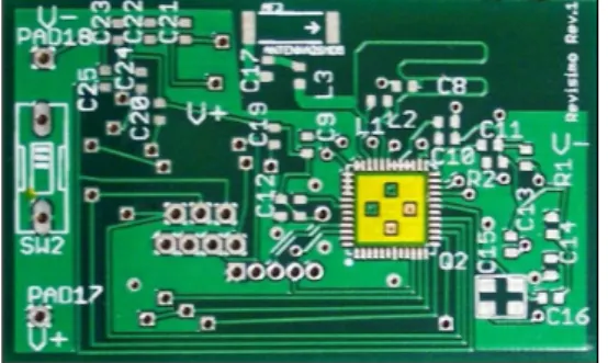
The metal is located in four distinct locations as shown in Figure 17. The solid red circles shown in the figure are the locations at which the metal rings are located. The metal rings are covered in solder-mask making them appear to be light green with a dark green border. The light green should be removed and the dark green should remain. This can be done via a razor or any fine, sharp object.
[Fig. 17] Location of the ground metal covered in solder mask
Figure 18 below shows what the board should look like after metal section has been taped, and the bottom and right grounding metals have been exposed. The upper and leftmost pads have been left covered to show the difference between a covered and an uncovered ground metal pad.
[Fig. 18] Picture of the board after taping and scraping
[Fig. 19] Corrected PCB Layout of the Bandage control board
The design flaws presented in our first spin of the board have been rectified via software. Both the top and the bottom copper have been changed to be connected to ground. The top solder-mask stop layer has been modified on the bandage PCB layout to uncover the grounding metal. Figure 19 shows corrected PCB Layout of Bandage control board.
Finally, in order to complete and measure more accurate human core-body temperature a flex PCB are required.
References
[1] Taftan Data, "Fourier's Law of Heat Conduction."
[Online] Available
http://www.taftan.com/thermodynamics/FOURIER.HTM,
1998.
[2] Thinking Electronic Industrial Co. LTD., “CPTC Thermistor Introduction.” Online: Available
http://www.thinking.com.tw/documents/en-PTC- introduction.pdf: accessed March 3, 2009.
[3] J. Lee, Y. Su, C. Shen, "A Comparitive Study of Wireless Protocols: Bluetooth, UWB, ZigBee, and Wi-Fi." 2007.
Jang Dong-Wook
[Regular Member]• Dec. 2009 : Mississippi State University(BS)
<Research Interests>
Automatic Control, Wireless Communication, Cloud Computing
Jang Sung-Whan
[Regular Member]• Feb. 1982 : Department of electrical engineering, Yonsei University(Ph. D.)
• Mar. 1985 ~ Feb. 1986 : Department of electrical &
computer engineering, Northwestern University research professor.
• Jan. 2005 ~ Jan. 2006 : Computer science engineering, Mississippi State University exchange professor.
• Mar. 1980 ~ current : Department of electrical &
information engineering, Wonkwang University professor.
<Research Interests>
Automatic Control, Application of Intelligence Control
Jeong Byoung-Jo
[Regular Member]• Feb. 2004 : Department of electrical engineering, Wonkwang University (MS)
• Mar. 2004 ~ Currently : Department of electrical engineering, Wonkwang University (Doctor's course)
• Jun. 2010 ~ current : ChangJun Co., Ltd. Senior researcher
<Research Interests>
Automatic Control, Image Processing
Hyun-Seob Cho
[life Member]• Feb. 1990 : Department of electrical engineering, Wonkwang University(BS)
• Feb. 1992 : Department of electrical engineering, Wonkwang University(MS)
• Feb. 1996년 : Department of electrical engineering, Wonkwang University(Ph. D.)
• Jan. 1996 ~ Jun. 1997 : Department of Electrical and Computer Engineering, University of California Irvine(UCI) researcher
• Mar. 1997 ~ current : Department of Digital Broadcast engineering, ChungWoon University Associate professor
<Research Interests>
Electrical Engineering, Factory Automation, Electron Application