Optimization of MRI Protocol for the Musculoskeletal
System
근골격계 자기공명영상 프로토콜의 최적화
Hong Seon Lee, MD
1,2, Young Han Lee, MD
1,2* , Inha Jung, MD
1,2, Ok Kyu Song, MD
1,2, Sungjun Kim, MD
2,3,
Ho-Taek Song, MD
1,2, Jin-Suck Suh, MD
1,21Department of Radiology, Severance Hospital, Yonsei University College of Medicine, Seoul, Korea
2Department of Radiology, Research Institute of Radiological Science, Center
for Clinical Imaging Data Science (CCIDS), Yonsei University College of Medicine, Seoul, Korea
3Department of Radiology, Gangnam Severance Hospital, Yonsei University College of Medicine, Seoul, Korea
Magnetic resonance imaging (MRI) is an essential modality for the diagnosis of musculoskeletal system defects because of its higher soft-tissue contrast and spatial resolution. With the recent development of MRI-related technology, faster imaging and various image plane reconstruc- tions are possible, enabling better assessment of three-dimensional musculoskeletal anatomy and lesions. Furthermore, the image quality, diagnostic accuracy, and acquisition time depend on the MRI protocol used. Moreover, the protocol affects the efficiency of the MRI scanner.
Therefore, it is important for a radiologist to optimize the MRI protocol. In this review, we will provide guidance on patient positioning; selection of the radiofrequency coil, pulse sequences, and imaging planes; and control of MRI parameters to help optimize the MRI protocol for the six major joints of the musculoskeletal system.
Index terms Musculoskeletal System; Musculoskeletal Diseases; Joints
서론
자기공명영상(magnetic resonance imaging)이 도입된 이래, 임상에서 영상의학 진단에 대한 의존도가 높아지면서 그 정확도와 편의성에 대한 요구도 높아지고 있다. 근골격계 분 야에서 자기공명영상은 다른 진단 기법에 비해 연부 조직에 대한 다양한 대조도 및 높은 해 상력을 제공함으로써 가장 중요한 영상 진단 기기로 활용되어 왔다. 최근 더욱 빠르게 자기 공명영상 촬영이 가능해지고, 다양하게 영상면을 재구성할 수 있게 되면서, 입체적인 근골 격계의 구조와 이상 소견을 파악하는데 중요도가 높아지고 있다.
Received October 30, 2019 Revised January 8, 2020 Accepted January 21, 2020
*Corresponding author Young Han Lee, MD Department of Radiology, Yonsei University College of Medicine,
50-1 Yonsei-ro, Seodaemun-gu, Seoul 03722, Korea.
Tel 82-2-2228-7400 Fax 82-2-2227-8337 E-mail radiologie@gmail.com This is an Open Access article distributed under the terms of the Creative Commons Attribu- tion Non-Commercial License (https://creativecommons.org/
licenses/by-nc/4.0) which permits unrestricted non-commercial use, distribution, and reproduc- tion in any medium, provided the original work is properly cited.
ORCID iDs Hong Seon Lee https://
orcid.org/0000-0003-2427-2783 Young Han Lee
https://
orcid.org/0000-0002-5602-391X Inha Jung
https://
orcid.org/0000-0001-5999-1281 Ok Kyu Song
https://
orcid.org/0000-0002-3914-9203 Sungjun Kim
https://
orcid.org/0000-0002-7876-7901 Ho-Taek Song
https://
orcid.org/0000-0002-6655-2575 Jin-Suck Suh
https://
orcid.org/0000-0001-9455-9240
근골격계 자기공명영상은 다른 부위와 비교하여 구별되는 여러 가지 특성들이 있으므로 이를 잘 이해하고 있어야 한다. 첫째로, 연부 조직 및 골수에는 많은 양의 지방 조직이 분포하고 있는데, 이러한 조직 내의 병변의 대조도를 높이기 위해서는 지방 억제 기법(fat suppression technique) 을 사용하는 것이 중요하다. 해당 기법으로 Chemically Selective Suppression (CHESS), Short Tau Inversion Recovery (이하 STIR), Spectral Presaturation with Inversion Recovery (SPIR), Spectral Attenuated Inversion Recovery (SPAIR), Dixon method를 이용한 iterative decom- position of water and fat with echo asymmetry and the least-squares estimation (IDEAL) 및 modified DIXON 기법 등이 있다. 각각의 기법에 따른 장점과 단점이 존재하므로 개별적인 특성 과 임상적 적용을 잘 이해하고 있는 것이 중요하다(1). 둘째로, 양성자 밀도 강조 영상(proton- density-weighted imaging; 이하 PDWI)이 널리 이용되는 특징이 있다. 양성자 밀도 강조 영상은 반월판(meniscus) 등의 섬유 연골(fibrocartilage) 혹은 인대(ligament)의 구조를 평가할 때 사용 되며(2), 3D 등방성 영상(isotropic imaging) 획득에 장점이 있고 이를 통해 관절 내 해부학적 구 조를 세밀하게 평가하는데 도움이 된다(3). 셋째로, 정형외과적 혹은 척추외과적 수술 후 영상에서 금속 삽입물(metallic implant) 등으로 인해 발생하는 인공물(artifact)을 줄이기 위한 여러 가지 금속 인공물 감소 기법(metal artifact reduction technique)들을 사용한다. 대표적으로 STIR 및 고속 스핀 에코(fast spin echo/turbo spin echo; 이하 FSE/TSE), high band-width 기법 등을 이 용하며, slice encoding metal artifact correction (SEMAC) 및 multi-acquisition with variable resonance image combination (MAVRIC) 등의 최신 기법들이 소개되고 있다(4, 5).
근골격계 자기공명영상에서 조영제(contrast agent)를 사용하는 방법은 크게 두 가지로 혈관 내로 주입하는 방법과 직접 관절강 내에 주입하는 방법이다. 혈관 내 주입을 통한 조영증강 검사 를 시행하면, 종양성 질환 및 감염성, 염증성 질환에서 병변의 가시화, 병변의 범위 파악 및 악성 종양의 병기 설정 정확도 등을 향상시키는 데 도움이 된다(6, 7). 관절강 내에 희석한 가돌리늄 조 영제를 주입하여 직접 자기공명관절조영술(direct MR arthrography)을 시행하면, 세밀한 구조물 사이 공간을 넓힐 수 있고 연부 조직의 대조도를 극대화하여 관절 연골, 섬유 연골 및 인대 등의 병 변에 대하여 진단율을 향상시킬 수 있다(8).
따라서, 이러한 근골격계 자기공명영상의 특징을 이해하고, 근골격계 구조물과 병변들을 적절 하게 촬영할 수 있으려면, 임상적 적응증에 맞는 자기공명영상의 최적화에 대해 이해하고 있어야 한다. 또한 이에 따라 영상의 질과 획득 시간이 결정되어 진단 정확도 및 자기공명영상 장치의 효 율적인 운용에 영향을 주기 때문에 자기공명영상의 최적화 방법을 숙지하는 것은 영상의학과 의 사의 가장 중요한 역할 중에 하나라고 할 수 있다.
이 종설에서 근골격계 자기공명영상의 6개 주요 관절 별로 환자 자세, radiofrequency 코일 선
택, 권장 펄스 대열, 영상면 및 스캔 파라미터에 대해 알아봄으로써 자기공명영상 최적화에 도움
이 되는 지침을 제시하고자 한다.
근골격계 자기공명영상 프로토콜의 최적화: 견관절 (Optimization of Shoulder MRI Protocol) 환자 자세(Patient Positioning)
환측 팔을 몸통 옆으로 둔 바로 누운 자세(supine position)로 촬영하며, 관절을 중립위(neutral position) 혹은 약간의 외회전(external rotation) 자세로 둔 뒤, 가능하면 견관절이 중앙에 가깝게 위치하여 촬영하기를 권장한다. 자기공명관절조영술(MR arthrography)을 시행할 때는 외전-외 회전(abduction and external rotation; ABER) 자세가 전하방 관절순(labrum) 파열 진단의 민감 도를 높이고 회전 근개 파열(rotator cuff tear), 특히 관절면 부분 파열 진단의 정확도를 높일 수 있다(9-13).
코일 선택(Coil Selection)
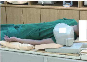
신호대잡음비(signal-to-noise ratio; 이하 SNR)의 극대화를 위해 견관절 전용 코일은 필수적이 며(Fig. 1), 적절한 다채널의 유연 코일(flexible coil)을 이용할 수 있다.
펄스열, 영상면, 스캔 파라미터(Pulse Sequence, Imaging Plane, Scan Parameter)
고식적 자기공명영상(Conventional MRI)
견관절 자기공명영상 검사는 일반적으로 사위 관상(oblique coronal), 사위 시상(oblique sagit- tal), 축상(axial) 영상을 얻는다. 사위 관상 영상은 관절와(glenoid fossa)에 직각으로 얻으며, 사위 시상 영상은 사위 관상 영상면에 수직이거나 혹은 관절와에 평행하도록 얻는다(Fig. 2). 대한근골 격영상의학회에서 2017년 발간한 근골격계 자기공명영상의 표준 촬영 프로토콜(14) 및 2019년 대 한영상의학회에서 발간한 특수의료장비 길라잡이에 의하면(15), 견관절 자기공명영상 검사에서 절편 두께(slice thickness)는 3 mm 이하, 절편 간격(interslice gap)은 10% 이하를 권장하며, 영 상 범위(field of view; 이하 FOV)는 16 cm 이하, 격자 수(matrix number)는 256 × 192 이상을
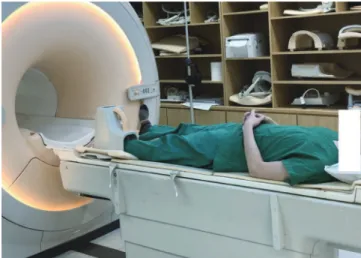
Fig. 1. Dedicated shoulder RF coil.
The shoulder is slightly externally rotated, and the shoulder cup of the RF coil is attached to the shoulder using the height adjustment bar. Since the shoulder joint is an off-center joint, it should be positioned at the center of the bore and the RF coil should be closely attached to the shoulder joint.
RF = radiofrequency
권장한다. Table 1에 근골격계의 6개 주요 관절에 대한 스캔 파라미터를 간략히 정리하였다. 각 영 상면의 스캔 방법 및 범위, 포함되어야 하고 확인할 수 있는 해부학적 구조물은 Table 2와 같다(14).
직접 자기공명관절조영술(Direct MR Arthrography)
희석한 가돌리늄 조영제 혹은 생리식염수를 관절강에 직접 주사한 뒤 얻은 영상을 이용하면, 견 관절 불안정성과 연관된 병변의 진단 정확도를 높일 수 있다(13, 16, 17). 그 밖에도 회전 근개의 부 분 파열이나 수술 후 재파열의 경우에서 진단력을 높일 수 있다(18-23). 조영제 주입은 전방 접근 법(anterior approach)을 가장 많이 이용하며, 견관절을 외회전(external rotation)시킨 자세에서 시행한다. 바늘의 진입점(entry point)은 관절와상완관절(glenohumeral joint)에서 상완골두
Fig. 2. Imaging plane of shoulder MRI.A-D. In shoulder MRI, based on axial images (A and C), the oblique coronal images (B) are obtained at right angles to the glenoid fossa (A), and the oblique sagittal images (D) are obtained perpendicular to the oblique coronal plane or parallel to the glenoid fossa (C). On the oblique coronal image (B), the glenoid la- brum (asterisks) and the long course of the supraspinatus tendon and its attachment (arrow) to the greater tuberosity are well visualized. On the oblique sagittal image (D), the muscles forming the rotator cuff (aster- isks) are visible. Clockwise from the 12 o’ clock position, the supraspinatus muscle, infraspinatus muscle, teres minor muscle, and subscapularis muscle are depicted.
A
C
B
D
(humeral head)에 가까운 내측 부분이다. 이 부위를 소독하고, 20~22 G 바늘을 관절 내로 주입한 뒤, 최소한의 요오드성 조영제(0.5~1 mL)로 바늘 끝이 관절강 내에 있음을 확인한다. 가돌리늄 조 영제는 생리식염수에 0.08~0.1 mmoL/kg의 농도로 희석한 후에 주사한다. 필요 시 국소마취제를 사용할 수도 있다. 주입하는 조영제의 양은 10~15 mL 정도로 한다. 조영제가 관절 내에 잘 들어간 것이 확인되면, 축상, 사위 관상, 그리고 사위 시상면에 대해 지방 억제 T1 강조 영상(fat sup- pressed T1-weighted image; 이하 T1WI), 사위 관상면 T2 강조 영상(oblique coronal T2WI), 사 위 시상 T1 강조 영상(oblique sagittal T1WI) 및 T2 강조 영상(T2WI)을 촬영한다. 적어도 하나의 T2 계열의 펄스열을 포함하여 관절강(joint cavity)과 연결이 없는 구조물 및 병변도 확인할 수 있 도록 한다. 가돌리늄 조영제 없이 생리식염수만 주입하는 경우는 T1 강조 영상 대신 T2 강조 영상 을 기본으로 프로토콜을 구성해야 한다. 조영제 주입 후 촬영까지 20분 이내가 소요되는 것이 이 상적이다.
간접 자기공명관절조영술(Indirect MR Arthrography)
조영제를 직접 관절강 내 주입하지 않고, 정맥주사 후 관절 활액막을 통해 확산시키는 방식을 통해 점액낭(bursa), 관절낭(joint capsule), 건초(tendon sheath) 등이 조영증강되는 방식으로 관절 조영 효과를 얻을 수 있다(21, 24). 조영제 정맥주사 후 환자에게 어깨를 움직이거나 운동을 하게 하고, 약 5~15분 후 축상면, 사위 관상면, 사위 시상면에 대해 지방 억제 T1 강조 영상, 사위 관상면 T2 강조 영상, 사위 시상면 T1 강조 영상 및 T2 강조 영상을 촬영한다.
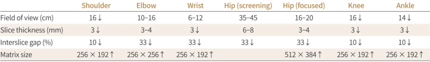
Table 1. Musculoskeletal MRI Scan Parameters
Shoulder Elbow Wrist Hip (screening) Hip (focused) Knee Ankle
Field of view (cm) 16↓ 10–16 6–12 35–45 16–20 16↓ 14↓
Slice thickness (mm) 3↓ 3–4 3↓ 6–8 3–4 3↓ 3↓
Interslice gap (%) 10↓ 33↓ 33↓ 33↓ 33↓ 10↓ 10↓
Matrix size 256 × 192↑ 256 × 256↑ 256 × 192↑ 512 × 384↑ 256 × 192↑ 256 × 192↑
↓ = less than or equal to, ↑ = greater than or equal to
Table 2. Shoulder: Scan Coverage and Anatomical Structures Involved
Scanning Axis and Coverage Anatomic Structures Oblique coronal Anteriorly, coracoid process
Posteriorly, scapular spine
Rotator cuff, acromioclavicular joint, biceps long head tendon, glenoid labrum, glenohumeral ligament, axillary recess, deltoid muscle
Oblique sagittal Medially, spinoglenoid notch
Laterally, greater tuberosity of humerus
Rotator cuff, acromioclavicular joint, rotator interval, biceps long head tendon, coracohumeral ligament,
glenohumeral ligament Axial Superiorly, acromioclavicular joint
Infeiorly, axillary recess
Acromioclavicular joint, subscapularis tendon, biceps long head tendon, labrum, coracohumeral ligament
근골격계 자기공명영상 프로토콜의 최적화: 주관절 (Optimization of Elbow MRI Protocol)
환자 자세(Patient Positioning)
환자가 엎드려서(prone position) 팔을 머리 위로 올린 자세는 촬영 부위를 균일한 자장 중심 (magnetic isocenter)에 위치시킬 수 있는 반면, 촬영이 길어지면 환자가 불편감을 느낄 수 있고 이로 인한 불수의적인 움직임에 의하여 인공물(artifact)이 발생할 수 있다(25, 26). 환자가 바로 누 운 자세(supine position)에서 주관절(elbow)을 환자의 몸통 옆에 위치시키고 촬영할 경우에는 환자의 불편감은 감소시킬 수 있지만 불균질한 자장 때문에 지방 억제가 불균질하게 되어 영상의 질이 저하될 수 있는 단점이 있다.
코일 선택(Coil Selection)
일반적으로 환자의 주관절 크기에 적합한 코일이 권장되고(27), 최근 높은 채널의 다중 채널 유 연 코일(flexible coil)이 보급되어 주관절 영상에 이용할 수 있다(Fig. 3). 크기가 맞는다면 소아에 서는 수관절 코일(wrist coil)을, 체구가 큰 성인에서는 슬관절 코일(knee coil)을 사용할 수도 있 다. 최적의 영상을 위해서는 주관절 크기에 적합한 코일을 권장한다.
펄스열, 영상면, 스캔 파라미터(Pulse Sequence, Imaging Plane, Scan Parameter)
관절 내 구조물들을 확인하기 위한 영상 범위(FOV)는 10~16 cm 정도가 적합하다(25, 28-30). 코 일이 충분한 신호대잡음비(SNR)를 제공한다면 가급적 영상 범위를 작게 사용하는 것이 좋다(29).
대한근골격영상의학회에서 2017년 발간한 근골격계 자기공명영상의 표준 촬영 프로토콜(14)에서 는 절편 두께(slice thickness)는 3~4 mm를 권장한다. 3 mm 이하의 절편 두께를 얻기 위해서는 3D 펄스열이 필요할 수 있다. 고식적인 2D 펄스열에서는 절편 간격(interslice gap)이 절편 두께의 33%가 넘지 않도록 해야 충분한 촬영 범위를 획득하고 크로스 토크(cross talk)로 인한 신호 손실 을 방지할 수 있다. 주관절 자기공명영상 촬영에서 격자 수(matrix number)는 256 × 256 이상을
Fig. 3. Elbow flexible RF coil.
The coil is a flexible RF coil that can be used for small joints. The patient is in close contact with the elbow joint. Depending on the physique of the patient, small and medium sizes are available.
RF = radiofrequency
권장한다. 각 영상면의 스캔 방법 및 범위, 포함되어야 하고 확인할 수 있는 해부학적 구조물은 아 래 Table 3과 같다(14).
주관절 자기공명영상 검사의 영상면은 축상(axial), 관상(coronal), 시상(sagittal) 영상을 모두 얻는 것이 권장된다(25, 28). 축상 영상은 전완(forearm) 및 상완(upper arm)에 수직한 평면으로 얻으며, 요골 조면(radial tuberosity)을 포함시킨다(25). 관상면은 양측 상과(medial and lateral epicondyle)를 포함하는 면에 평행하게 촬영하며, 시상면은 위와 같이 촬영된 관상면에 수직인 평면으로 촬영한다(26, 28). 주관절을 굴곡(flexion) 시킨 상태에서 촬영해야 한다면 전완 및 상완 에서 각각 축상 및 관상 영상을 얻어야 한다.
주관절 자기공명영상에서 여러 단면의 여러 펄스 대열들을 조합하고 응용하면, 임상적 필요에 따른 중요한 정보를 추가로 얻을 수 있다. 관상면 영상은 측부인대(collateral ligament), 공통 굴 곡건(common flexor tendon), 공통 신전건(common extensor tendon) 및 주관절 관절면의 확 인에 중요하다. 축상면 영상은 주요 혈관 및 신경, 건, 근육 등의 평가에 유용하다. 시상면 영상은 주두(olecranon)과 구돌와(coronoid fossa)를 포함한 주관절 관절면 평가에 도움을 준다. 기본적 으로 골수 부종(bone marrow edema), 출혈(hemorrhage), 연부 조직 부종 등의 소견을 확인하 기 위해 T2 강조 영상를 이용하는데, 지방 억제 기법을 추가할 경우 병변을 좀 더 민감하게 확인할 수 있다(25). STIR 영상은 골수 부종 변화를 감지하는데 민감도가 우수하나, 촬영 시간이 비교적 길고 해상도가 떨어진다는 한계가 있다(25). T1 강조 영상은 신경이나 골수의 이상 소견을 확인하 는데 사용할 수 있다.
근골격계 자기공명영상 프로토콜의 최적화: 수관절 (Optimization of Wrist MRI Protocol)
환자 자세(Patient Positioning)
코일의 종류와 자기공명영상 기기에 따라 환자의 자세 및 상지의 자세를 결정하게 된다. 일반적 으로 바로 누운 자세(supine position)에서 환측 팔을 몸통의 측면에 두거나, 환자가 옆으로 비스 듬히 누운 자세에서 손목을 가능하면 자장의 중앙에 위치하도록 한다. 그 밖에도 손목을 자기 중 심(magnetic isocenter)에 위치시키기 위해, 엎드린 자세(prone position), 비스듬히 엎드린 자세
Table 3. Elbow: Scan Coverage and Anatomical Structures InvolvedScanning Axis and Coverage Anatomic Structures Axial Perpendicular to humerus and proximal radius
and ulna
Humerus epicondyle and radial tuberosity should be included
Distal biceps and brachialis, common flexor tendon and common extensor tendons, ulnar nerve and adjacent structures Coronal Parallel to epicondylar axis
Must include soft tissue in the anterior and posterior aspect
Collateral ligament complex, common flexor tendon, common extensor tendon Sagittal Perpendicular to the epicondylar axis Radiocapitellar and ulnotrochlear joint,
triceps brachii tendon
(semiprone), 혹은 바로 누운 자세(supine position)에서 손목을 머리 위로 올려 촬영할 수 있으 나(31, 32), 오랜 시간 촬영 시 환자가 불편해할 수 있으므로 주의를 요한다. 최신 장비는 손목 전용 코일이 침대에 고정되어 엎드린 자세에서 차려 자세로 촬영할 수 있는 경우가 많다.
코일 선택(Coil Selection)
가능한 수관절 전용 코일을 사용하는 것을 권한다(Fig. 4). 병렬 영상(parallel imaging) 및 신호 대잡음비(SNR)의 극대화를 위해 다중 채널 수신 전용 코일(multi-channel receive only coil)이 많이 쓰이고 있다(33-35).
펄스열, 영상면, 스캔 파라미터(Pulse Sequence, Imaging Plane, Scan Parameter)
1.5 Tesla (이하 T)와 3 T 기기 모두에서 기본적인 스핀 에코(spin echo, SE) 펄스열에 대해서는 축상(axial), 관상(coronal), 시상(sagittal)면 영상을 모두 얻는 것이 바람직하다. 이를 바탕으로 평 가하고자 하는 구조에 따라 몇 가지 펄스열을 추가하는 것으로 프로토콜을 구성하는 것이 좋다.
수관절 자기공명영상 검사에서 권장하는 펄스열은 축상 T1 강조 영상(axial T1WI), 축상 지방 억 제 T2 강조 혹은 T2* 강조 영상(axial fat suppressed T2-weighted or T2*WI), 관상 지방 억제 T2 강조 영상(coronal fat suppressed T2WI), 시상 T2 강조 영상(sagittal T2WI)이다. 수관절의 작은 병변에 대한 조영증강 영상을 얻고자 할 때는 고속 스핀 에코(FSE/TSE) 펄스열을 이용한 T1 강조 영상이나 3D 경사 에코 영상(gradient-echo sequence)을 이용하는 것이 좋다(34, 35). 관상면에 대해 얇은 절편 두께(slice thickness)를 위하여 3D 경사 에코 영상(gradient-echo sequence)을 사용할 수 있다. 대한근골격영상의학회에서 2017년 발간한 근골격계 자기공명영상의 표준 촬영 프로토콜(14) 및 미국방사선학회(American College of Radiology)의 프로토콜 가이드라인(36)에 의하면 영상 범위(FOV)는 골절을 보기 위한 목적이라면 16 cm 이하, 삼각 섬유연골 복합체 및 수 관절의 인대 등을 평가하기 위해서는 6~12 cm 정도를 권장한다. 절편 두께(slice thickness)는 3 mm 이하로 하는 것을 권장하며, 절편 간격(interslice gap)은 절편 두께(slice thickness)의 33%
를 넘지 않도록 권장한다. 수관절 자기공명영상 촬영에서 격자 수(matrix number)는 256 × 192
Fig. 4. Dedicated wrist RF coil.
By using the RF coil dedicated to the wrist joint, the patient can main- tain the joint in a neutral position while laying supine, thereby enabling stable image acquisition. The superman position may be considered to place the wrist joint at the center of the magnetic field. However, if the acquisition time is long, the patient may feel uncomfortable.
RF = radiofrequency
이상을 권장한다. 각 영상면의 스캔 방법 및 범위, 포함되어야 하고 확인할 수 있는 해부학적 구조 물은 아래 Table 4와 같다(14).
자기공명관절조영술(MR Arthrography)
견관절과 마찬가지로 직접 자기공명관절조영술(direct MR arthrography)은 희석한 조영제를 요골수근관절(radiocarpal joint)에 관절 내 주사하거나, 요골수근관절, 중수근관절(midcarpal joint), 원위요척관절(distal radioulnar joint)을 포함한 세 부위에 관절 내 주사를 한다. 침습적인 검사이므로 검사의 위험성과 관절 조영술로 얻을 수 있는 이점을 충분히 고려하여 시행한다(37, 38). 직접 자기공명관절조영술은 1.5 T에서도 고식적 촬영보다 좋은 진단능을 보이는 것으로 알려 져 있다. 3 T 자기공명영상에서는 더 뛰어난 공간 해상도 영상이 더해져 진단능이 한층 더 높아질 수 있다. 직접자기공명관절 조영술를 시행하게 되면 삼각 섬유 연골 복합체(triangular fibrocar- tilage complex), 수근골 인대(carpal interosseous ligaments), 관절 연골(articular cartilage) 손 상의 진단력이 향상될 수 있다(39, 40). 간접 자기공명관절조영술(indirect MR arthrography)는 조영제를 정맥주사 후 짧은 시간 후의 지연 영상을 얻거나 수관절 운동 후에 영상을 얻는 방법이 다(39, 41).
근골격계 자기공명영상 프로토콜의 최적화: 고관절 (Optimization of Hip MRI Protocol)
환자 자세(Patient Positioning)
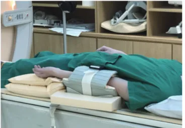
환자는 바로 누운 자세(supine position)를 취하고, 다리를 내회전(internal rotation)하여 양발 끝이 마주 보도록 하여 검사를 시행한다. 이를 위해 필요에 따라 발을 고정하거나, 무릎을 약간 구 부릴 수 있도록 베게 등을 무릎 밑에 받쳐주면 환자가 편하게 느낄 수 있다.
코일 선택(Coil Selection)
일반적으로 동체 코일(body coil) 또는 토르소 코일(torso coil)을 사용하여 넓은 영상 범위
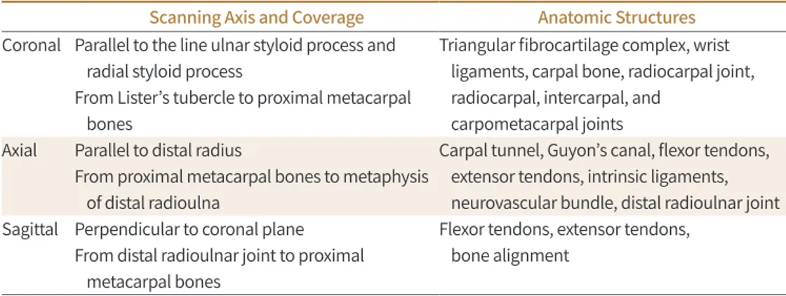
Table 4. Wrist: Scan Coverage and Anatomical Structures Involved
Scanning Axis and Coverage Anatomic Structures Coronal Parallel to the line ulnar styloid process and
radial styloid process
From Lister’s tubercle to proximal metacarpal bones
Triangular fibrocartilage complex, wrist ligaments, carpal bone, radiocarpal joint, radiocarpal, intercarpal, and
carpometacarpal joints Axial Parallel to distal radius
From proximal metacarpal bones to metaphysis of distal radioulna
Carpal tunnel, Guyon’s canal, flexor tendons, extensor tendons, intrinsic ligaments, neurovascular bundle, distal radioulnar joint Sagittal Perpendicular to coronal plane
From distal radioulnar joint to proximal metacarpal bones
Flexor tendons, extensor tendons, bone alignment
(FOV)를 검사할 수 있도록 한다(Fig. 5). 이렇게 하면 양측 골반과 고관절 전체를 동시에 볼 수 있 으며, 증상이 한쪽에만 있는 경우라도 반대쪽 고관절과 비교함으로써 질병을 감별하는데 도움을 얻을 수 있다(42). 이후 필요에 따라 병변 부위로 영상 범위를 좁히거나 한쪽씩 따로 촬영하면 더 높은 공간 해상도로 구조를 자세하게 검사할 수 있다.
펄스열, 영상면, 스캔 파라미터(Pulse Sequence, Imaging Plane, Scan Parameter)
고관절 자기공명영상 검사는 일반적으로 관상(coronal), 축상(axial), 시상(sagittal) 영상을 얻는 다. 이 중에서 가장 중요한 것은 관상면 영상인데, 관상 T1 강조 영상(coronal T1WI) 및 관상 지방 억제 T2 강조 영상(coronal fat suppressed T2WI) 영상을 통해 대퇴 골두 무혈성골괴사(osteone- crosis of femoral head) 및 골절 등을 진단할 수 있기 때문이다(43, 44). 천골(sacrum)의 윗부분 에 평행하도록 사위 관상(oblique coronal) 영상을 얻음으로써 천장 관절(sacroiliac joint)을 평가 하는데 도움을 얻을 수도 있으며(45, 46), 관절순(labrum) 및 연골(cartilage)의 정확한 평가와 대 퇴비구 충돌증후군(femoroacetabular impingement syndrome)에서 대퇴 골두의 평가를 위해 방사형(radial) 영상 기법을 이용할 수 있다(47, 48). 위골반문(pelvic inlet)의 활꼴선(arcuate line) 에 평행하게 사위 축상(oblique axial) 영상을 얻을 수 있으며, 스포츠 탈장(athletic pubalgia)의 진단에 유용하다(49). 3D 영상은 대퇴 골두와 비구 연골(acetabular cartilage) 이상 소견을 정밀하 게 파악하는데 도움이 될 수 있다(50). 조영증강 T1 강조 영상(contrast enhancement T1WI)으로 는 활막염(synovitis), 감염성 질환, 종양성 질환 등을 평가할 수 있다.
일반적으로 전체 골반을 촬영하기 위해서 35~45 cm의 영상 범위가 필요하다. 이 경우에는 6~8 mm의 절편 두께(slice thickness)로 얻는 것을 권장한다(51). 고해상도 영상을 위해서는 특정 병 변이나 한쪽 고관절 부위만 포함하도록 영상 범위를 16~20 cm로 줄이거나, 절편 두께를 3~4 mm 로 줄이고 격자 수(matrix number)를 증가시키면 된다(52). 절편 간격(interslice gap)은 절편 두 께(slice thickness)의 33%를 넘지 않도록 권장한다. 각 영상면의 스캔 방법 및 범위, 포함되어야 하고 확인할 수 있는 해부학적 구조물은 아래 Table 5와 같다(14).
고관절 자기공명영상 검사에서 권장하는 펄스열은 다음과 같으며, 반드시 포함시켜야 하는 대
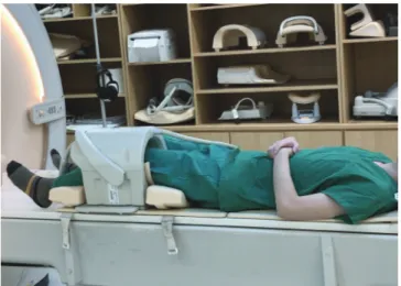
Fig. 5. Torso RF coil for hip joint imaging.The coil is a multi-channel torso RF coil that can cover a wide field of view required for hip joint MRI, enabling imaging of both the hips and pelvic bones.
RF = radiofrequency
열은 별표(*)로 표시하였다(42).
- 관상 T1 강조 영상(coronal T1WI)*
- 관상 지방 억제 T2 강조 영상(coronal fat suppressed T2WI)*
- 축상 T1 강조 영상(axial T1WI)*
- 축상 T2 강조 영상(axial fat suppressed T2WI)*
- 시상 T1 강조 영상(sagittal T1WI) - 시상 T2 강조 영상(sagittal T2WI)
고관절 자기공명관절조영술(Hip MR Arthrography)
관절순(labrum) 및 고관절 관절강(joint cavity)의 평가를 위해 희석한 가돌리늄 조영제를 이용 하여 자기공명관절조영술을 시행할 수 있다(53). 지방 억제 T1 강조 영상이 주로 사용되며, 관절낭 과 연결이 되어있지 않은 부위의 평가를 위해서는 적어도 하나의 T2 강조 영상이 필요하다.
근골격계 자기공명영상 프로토콜의 최적화: 슬관절 (Optimization of Knee MRI Protocol)
환자 자세(Patient Positioning)
환자는 바로 누운 자세(supine position)를 취하고, 환측 슬관절을 최대한 신전(extension)한 상태로 검사를 한다. 이 경우 고관절을 약간 외회전(external rotation)하면 환자가 조금 더 편한 자세로 검사를 받을 수 있다. 필요에 따라 다리가 움직이지 않도록 고정을 함으로써 움직임 인공 물(motion artifact)을 예방할 수 있다.
코일 선택(Coil Selection)
슬관절 자기공명영상에서는 신호대잡음비(SNR)를 높이기 위해 전용 코일(dedicated knee coil) 혹은 무릎 촬영에 적합한 표면 코일(surface coil)을 사용해야 한다(Fig. 6). 다중 채널 슬관절 코일 (multi-channel phase array knee coil)을 사용하면 신호대잡음비를 더 높일 수 있으며, 병렬 영 상 기법(parallel imaging)이 가능하여 영상 획득 시간(acquisition time)을 줄일 수 있다(54-56).
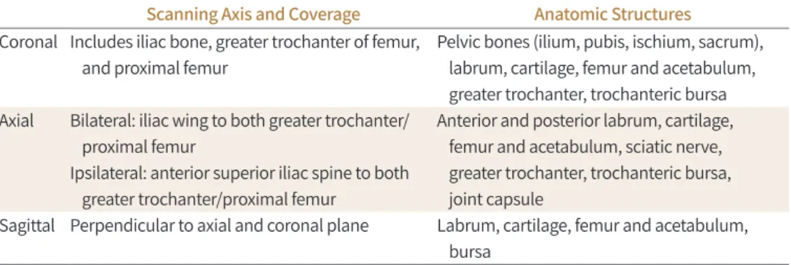
Table 5. Hip: Scan Coverage and Anatomical Structures Involved
Scanning Axis and Coverage Anatomic Structures Coronal Includes iliac bone, greater trochanter of femur,
and proximal femur
Pelvic bones (ilium, pubis, ischium, sacrum), labrum, cartilage, femur and acetabulum, greater trochanter, trochanteric bursa Axial Bilateral: iliac wing to both greater trochanter/
proximal femur
Ipsilateral: anterior superior iliac spine to both greater trochanter/proximal femur
Anterior and posterior labrum, cartilage, femur and acetabulum, sciatic nerve, greater trochanter, trochanteric bursa, joint capsule
Sagittal Perpendicular to axial and coronal plane Labrum, cartilage, femur and acetabulum, bursa
펄스열, 영상면, 스캔 파라미터(Pulse Sequence, Imaging Plane, Scan Parameter)
일반적으로 슬관절 자기공명영상은 축상(axial), 관상(coronal), 그리고 시상(sagittal) 영상을 모 두 얻는다. 다평면 영상(multiplanar imaging)은 직접 각을 주어 얻거나 영상 재구성(recon- struction)을 통해 얻을 수 있는데, 전방 십자인대(anterior cruciate ligament) 및 후방외측 모퉁 이 인대 구조물(posterolateral corner ligamentous complex) 등을 평가하는데 도움이 될 수 있 다. 예를 들어, 3D 등방성(isotropic) 고속 스핀 에코(FSE/TSE) 기법으로 영상을 얻으면, 보고자 하 는 구조물에 맞추어 다면 재구성(multiplanar reconstruction; MPR)을 할 수 있으므로 아주 작 거나 얇고, 복잡한 구조물을 검사하는데 유용하게 사용할 수 있다(57, 58).
주로 T1 강조 영상(T1WI) 혹은 양성자 밀도 강조 영상(PDWI)을 이용하여 반월 연골(menis- cus)을 평가하며, T2 강조 영상(T2WI)으로 인대 및 힘줄을 평가한다(59, 60). 지방 억제(fat sup- pression)를 하지 않은 T1 강조 영상을 이용하여 골수(bone marrow) 병변을 평가한다. 관절 연 골(articular cartilage)의 평가를 위해서는 양성자 밀도 강조 영상 혹은 T2 강조 영상을 얻으며 지방 억제를 하기도 한다. 또한, 임상적인 필요에 따라 조영증강 T1 강조 영상(contrast enhance- ment T1WI)을 얻을 수 있다.
대한근골격영상의학회에서 2017년 발간한 근골격계 자기공명영상의 표준 촬영 프로토콜(14) 및 2019년 대한영상의학회에서 발간한 특수의료장비 길라잡이에 의하면(15), 슬관절 자기공명영 상의 영상 범위(FOV)는 16 cm 이하를 권장한다. 임상적으로 슬관절 신전(extension) 메커니즘이 나 골수 병변을 평가하기 위해서 영상 범위를 더 넓히는 수도 있다. 절편 두께(slice thickness)는 3 mm 이하를 권장하며, 절편 간격(interslice gap)은 절편 두께의 10% 이하를 권장한다. 격자 수 (matrix number)는 256 × 192 이상을 권장한다(15).
스캔 범위(scanning coverage)는 앞쪽, 뒤쪽, 내측, 외측의 지지 구조물들, 예를 들어, 내측 및 외측 측부인대(medial collateral ligament and lateral collateral ligament) 등이 포함되어야 하 나 모든 영상면에서 요구되지는 않는다. 상방으로는 대퇴 사두근건의 원위부(quadriceps ten- don)와 슬개상 점액낭(suprapatella bursa)이 포함되어야 하며, 하방으로는 슬개건(patella ten- don) 및 거위발건(pes anserinus tendon)의 경골(tibia) 부착 부위 및 경골 결절(tibial tuberosi-
Fig. 6. Dedicated knee RF coil.
A type of dedicated RF coil for the knee joint, which can be separated up and down. When the knee joint is placed inside the coil, it is slightly flexed. Recently, radiologists have begun using the transmit-receiver coil, in which case the connectors are located on both sides.
RF = radiofrequency
ty)이 포함되어야 한다. 각 영상면의 스캔 방법 및 범위, 포함되어야 하고 확인할 수 있는 해부학적 구조물은 아래 Table 6과 같다(14).
슬관절 자기공명관절조영술(Knee MR Arthrography)
직접 및 간접 슬관절 자기공명관절조영술은 다양한 무릎의 내부 이상(internal derangement of knee), 수술 후 평가 및 관절 연골 평가에 유용하다고 알려져 있으며, 특히, 관절 연골 재생술 (articular cartilage transplantation) 후 이식편 평가에 도움이 될 수 있다(61-64). 간접 자기공명 관절조영술은 조영제를 정맥주사 후 관절 활액막(synovial membrane)을 통해 확산시키는 방식 을 통해 조영 효과를 얻는 방식으로 종양 및 관절염의 진단 및 진행 평가 등에 이용된다(65). 주로 지방 억제 T1 강조 영상(fat suppressed T1WI)이 이용되며, 관절강과 연결이 없는 병변까지 확인 할 수 있도록 적어도 하나의 T2 강조 영상을 포함시켜야 한다.
기타 고려사항(Specific Consideration)
슬관절 자기공명영상에서 발생할 수 있는 다양한 인공물(artifact)들을 예방하기 위해 다음과 같 은 기법들을 고려해 볼 수 있다. 환측 관절에 대해 고해상도 영상을 얻어야 하는 슬관절은 둘러겹 침 인공물(wraparound artifact)을 배제하는 것이 가장 중요하다. 둘러겹침 인공물을 막기 위해 위상 부호화(phase encoding) 방향으로 오버샘플링(oversampling)을 하거나, 위상 부호화 방향 과 주파수 부호화(frequency encoding) 방향을 바꾸거나, 혹은 양측 슬관절 사이에 차폐(radio- frequency shielding)를 할 수 있다(66, 67).
고자장(high field strengths)의 자기공명영상에서 화학 변위 인공물(chemical shift artifact) 및 자화율 인공물(susceptibility artifact)이 더 심하게 나타날 수 있는데, 이런 경우에는 수신기 주파수폭(receiver bandwidth)을 높이거나, 경사 에코 영상(gradient-echo imaging)을 피하고, 복셀(voxel)의 크기를 줄임으로써 인공물을 줄일 수 있다(66, 68, 69).
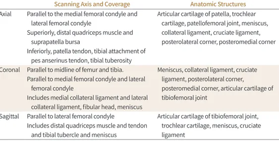
Table 6. Knee: Scan Coverage and Anatomical Structures Involved
Scanning Axis and Coverage Anatomic Structures Axial Parallel to the medial femoral condyle and
lateral femoral condyle
Superiorly, distal quadriceps muscle and suprapatella bursa
Inferiorly, patella tendon, tibial attachment of pes anserinus tendon, tibial tuberosity
Articular cartilage of patella, trochlear cartilage, patellofemoral joint, meniscus, collateral ligament, cruciate ligament, posterolateral corner, posteromedial corner
Coronal Parallel to midline of femur and tibia.
Parallel to medial femoral condyle and lateral femoral condyle
Includes medial collateral ligament and lateral collateral ligament, fibular head, meniscus
Meniscus, collateral ligament, cruciate ligament, posterolateral corner,
posteromedial corner, articular cartilage of tibiofemoral joint
Sagittal Parallel to lateral femoral condyle
Includes distal quadriceps muscle and tendon and tibial tubercle and meniscus
Articular cartilage of tibiofemoral joint, trochlear cartilage, meniscus, cruciate ligament
금속 삽입물(metallic implant)이 있는 경우에는 echo train length (ETL), 수신기 주파수폭, 격 자 수를 높이고, 영상 범위를 줄임으로써 인공물을 감소시킬 수 있으나, 금속 삽입물의 성분이나 방향에 따라 인공물을 줄이는데 한계가 있을 수 있다(64, 70).
근골격계 자기공명영상 프로토콜의 최적화: 족관절 (Optimization of Ankle MRI Protocol)
환자 자세(Patient Positioning)
환자는 바로 누운 자세(supine position) 혹은 엎드린 자세(prone position)로 누운 상태에 서 촬영한다. 일반적으로 족관절이와 발이 직각을 이룬 중립(neutral) 상태에서 촬영하지만 굴곡 (plantar flexion) 상태로도 촬영할 수 있다. 족관절을 굴곡하면 마술각 효과(magic angle arti- fact)가 감소되며 발가락이 발꿈치에 중첩되는 둘러겹침 인공물(aliasing artifact)을 감소시키는 장점이 있지만, 아킬레스건(Achilles tendon)이나 전거비인대(anterior talofibular ligament) 등 을 포함한 원위부 중요 구조가 왜곡되어 보여 판독이 어려울 수 있기 때문에 각각 임상적 목적에 적합하게 자세를 선택해야 한다(71, 72).
코일 선택(Coil Selection)
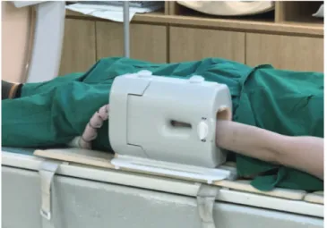
높은 해상도 및 신호대잡음비(SNR)를 위해 다중 채널 전용 코일을 권하며(73), 전용 코일을 사 용하면 환자 자세를 잡는 것이 편리하다(Fig. 7). 유연 코일(flexible coil) 사용 시 다중 채널 코일 을 권장하며, 유연 코일을 이용하는 경우 positioner를 이용하면 환자가 안정적인 자세를 잡는데 도움이 된다.
펄스열, 영상면, 스캔 파라미터(Pulse Sequence, Imaging Plane, Scan Parameter)
족관절 자기공명영상 검사는 족부의 장측 및 단측 영상을 모두 얻는다. 일반적으로 경골(tibia) 면에 맞추어 축상(axial), 관상(coronal), 시상(sagittal) 세 방향으로 영상을 얻는다. 힘줄 및 인대 검사 시에 관심 구조물의 장축과 평행한 영상과 직각인 방향으로 영상을 얻는 것이 도움이 된다.
대한근골격영상의학회에서 2017년 발간한 근골격계 자기공명영상의 표준 촬영 프로토콜(14) 및 2019년 대한영상의학회에서 발간한 특수의료장비 길라잡이에 의하면(15), 절편 두께(slice thick- ness)는 3 mm 이하, 절편 간격(interslice gap)은 절편 두께의 10% 이하, 영상 범위(FOV)는 14 cm 이하, 격자 수(matrix number)는 256 × 192 이상이 권장된다. 하지만 임상적으로 필요한 상 황에 따라 조절이 필요한데, 예를 들어, 아킬레스건(Achilles tendon) 파열의 경우 시상 영상의 영 상 범위가 22 cm까지 필요할 수 있고, 관상 영상에서는 작은 연골 병변이나, 인대 등을 평가하기 위해 12 cm 또는 그 이하의 영상범위가 효과적이다(74-76). 각 영상면의 스캔 방법 및 범위, 포함 되어야 하고 확인할 수 있는 해부학적 구조물은 아래 Table 7과 같다(14).
기본 프로토콜에는 양성자 밀도 강조 영상(PDWI) 또는 지방 억제(fat suppressed) 양성자 밀도
강조 영상을 축상, 관상, 시상 세 가지 영상면에서 얻을 수 있으며, 여기에 필요한 영상면의 T1 강
조 영상 및 T2 강조 영상, 지방 억제 T2 강조 영상 등을 추가로 획득할 수 있다. T1 강조 영상은 골 수염(osteomyelitis), 골연골 결손(osteochondral lesion), 부전 골절(insufficiency fracture) 등 과 같은 골수 병변이 의심될 때 선호되는 반면, 건(tendon)이나 인대(ligament) 병변이 의심되는 경우에는 양성자 밀도 강조 영상 혹은 T2 강조 영상과 같은 긴 이완 시간(relaxation time)을 가 지는 유체 민감성 펄스열(fluid sensitive sequence)이 선호된다(77, 78). T1 강조 영상 혹은 양성 자 밀도 강조 영상과 같은 짧은 에코시간(short echo time)을 가지는 펄스열에서는 주자기장 축 과 약 55도 각도로 주행하는 건(tendon)에서 발생하는 고신호의 인공물인 마술 각 인공물(magic angle artifact)을 주의해야 한다. 이는 주로 시상 영상에서 비골근(peroneal tendon), 후경골건 (posterior tibial tendon), 장지굴건(flexor digitorum longus tendon), 장족무지굴건(flexor hallucis longus tendon) 등의 구조물에서 흔히 발생한다(79). 연골 평가를 위해서는 일반적으로 2D 지방 억제 양성자 밀도 강조 영상, 지방 억제 T2 강조 영상, 그리고 3D T1 강조 경사 에코 펄스 열(gradient-echo sequence)이 흔히 사용된다. 원위 경골(distal tibia)와 거골 원개(talar dome) 의 연골 면을 적절히 분리시키기 위해서는 관상 영상에서 작은 영상 범위를 사용하여 공간 해상 도를 높이는 것이 효과적이다(66).
Fig. 7. Dedicated ankle RF coil.
The ankle joint RF coil is designed so that the lower leg and the foot are al- most at right angles to each other, enabling correct posture for imaging. If a flexible coil is used, a positioner may be used to enhance patient comfort.
RF = radiofrequency
Table 7. Ankle: Scan Coverage and Anatomical Structures Involved
Scanning Axis and Coverage Anatomic Structures Coronal Perpendicular to axial scans
Include calcaneus and metatarsal base
Deltoid ligaments, calcaneofibular ligament, tarsal tunnel, plantar fascia
Axial Parallel to the longitudinal axis of calcaneus including distal tibia and inferior margin of calcaneus
Posterior tibial tendon, peroneus longus/
brevis tendon, sinus tarsi, tibiofibular ligament, anterior talofibular ligaments, posterior talofibular ligament, spring ligament Sagittal Parallel to the longitudinal axis of talus
including both medial and lateral margin
Achilles tendon, sinus tarsi, plantar fascia
결론
근골격계 주요 관절 별로 자기공명영상을 최적화하는 원칙과 방법에 대해 알아보았다. 임상에 유용한 근골격계 자기공명영상을 구현하기 위해서는, 각 관절 별 다빈도 질환에 맞추어진 보편적 인 영상의 최적화와 함께 근골격계 통증 혹은 종양, 감염 등의 특정 질환을 감별하기 위한 보정된 프로토콜을 모두 구사할 수 있어야 한다. 이와 같이 근골격계 자기공명영상 기법의 기본을 숙지하 고 이를 임상 영역에서 응용하는 것은 영상의학과 의사의 중요한 역할이라 하겠다.
Author Contributions
Conceptualization, L.H.S., L.Y.H., K.S., S.H., S.J.; data curation, L.H.S., S.O.K., J.I., L.Y.H.; supervi- sion, K.S., S.H., S.J.; visualization, L.H.S., S.O.K., L.Y.H.; writing—original draft, L.H.S., S.O.K., J.I., L.
Y.H.; and writing—review & editing, L.Y.H., K.S., S.H., S.J.
Conflicts of Interest
The authors have no potential conflicts of interest to disclose.
REFERENCES
1. Del Grande F, Santini F, Herzka DA, Aro MR, Dean CW, Gold GE, et al. Fat-suppression techniques for 3-T MR imaging of the musculoskeletal system. Radiographics 2014;34:217-233
2. Korean Society of Magnetic Resonance in Medicine. Clinical magnetic resonance imaging. Seoul: Ilchokak 2015
3. Jung JY, Yoon YC, Kwon JW, Ahn JH, Choe BK. Diagnosis of internal derangement of the knee at 3.0-T MR imaging: 3D isotropic intermediate-weighted versus 2D sequences. Radiology 2009;253:780-787
4. Hargreaves BA, Worters PW, Pauly KB, Pauly JM, Koch KM, Gold GE. Metal-induced artifacts in MRI. AJR Am J Roentgenol 2011;197:547-555
5. Koch KM, Brau AC, Chen W, Gold GE, Hargreaves BA, Koff M, et al. Imaging near metal with a MAVRIC-SEMAC hybrid. Magn Reson Med 2011;65:71-82
6. American College of Radiology. ACR-SPR-SSR Practice parameter for the performance and interpretation of magnetic resonance imaging (MRI) of bone, joint, and soft tissue infections in the extremities. Avaiable at.
https://www.acr.org/-/media/ACR/Files/Practice-Parameters/MR-Bone-Joint-Infections.pdf?la=en. Pub- lished 2016. Accessed Jan 10, 2020
7. American College of Radiology. ACR-SPR-SSR practice parameter for the performance and interpretation of magnetic resonance imaging (MRI) of bone and soft tissue tumors. Avaiable at. https://www.acr.org/-/me- dia/ACR/Files/Practice-Parameters/MR-SoftTissue-Tumors.pdf?la=en. Published 2015. Accessed Jan 10, 2020
8. Steinbach LS, Palmer WE, Schweitzer ME. Special focus session: MR arthrography. Radiographics 2002;
22:1223-1246
9. Chandnani VP, Yeager TD, DeBerardino T, Christensen K, Gagliardi JA, Heitz DR, et al. Glenoid labral tears:
prospective evaluation with MRI imaging, MR arthrography, and CT arthrography. AJR Am J Roentgenol 1993;161:1229-1235
10. Cvitanic O, Tirman PF, Feller JF, Bost FW, Minter J, Carroll KW. Using abduction and external rotation of the shoulder to increase the sensitivity of MR arthrography in revealing tears of the anterior glenoid labrum. AJR Am J Roentgenol 1997;169:837-844
11. Davis SJ, Teresi LM, Bradley WG, Ressler JA, Eto RT. Effect of arm rotation on MR imaging of the rotator cuff.
Radiology 1991;181:265-268
12. Tuite MJ, De Smet AA, Norris MA, Orwin JF. MR diagnosis of labral tears of the shoulder: value of T2*-weight- ed gradient-recalled echo images made in external rotation. AJR Am J Roentgenol 1995;164:941-944 13. Willemsen UF, Wiedemann E, Brunner U, Scheck R, Pfluger T, Kueffer G, et al. Prospective evaluation of MR
arthrography performed with high-volume intraarticular saline enhancement in patients with recurrent an-
terior dislocations of the shoulder. AJR Am J Roentgenol 1998;170:79-84
14. Jee WH. Musculoskeletal magnetic resonance imaging (MRI). Seoul: Korean Society of Musculoskeletal Ra- diology, Korean Society of Radiology 2017
15. Korean Society of Radiology. Quality assurance guidelines for special medical equipments. Seoul: Korean Institute for Accreditation of Medical Imaging 2019
16. Waldt S, Burkart A, Lange P, Imhoff AB, Rummeny EJ, Woertler K. Diagnostic performance of MR arthrogra- phy in the assessment of superior labral anteroposterior lesions of the shoulder. AJR Am J Roentgenol 2004;182:1271-1278
17. Palmer WE, Caslowitz PL. Anterior shoulder instability: diagnostic criteria determined from prospective analysis of 121 MR arthrograms. Radiology 1995;197:819-825
18. Duc SR, Mengiardi B, Pfirrmann CW, Jost B, Hodler J, Zanetti M. Diagnostic performance of MR arthrography after rotator cuff repair. AJR Am J Roentgenol 2006;186:237-241
19. Pfirrmann CW, Zanetti M, Weishaupt D, Gerber C, Hodler J. Subscapularis tendon tears: detection and grad- ing at MR arthrography. Radiology 1999;213:709-714
20. Flannigan B, Kursunoglu-Brahme S, Snyder S, Karzel R, Del Pizzo W, Resnick D. MR arthrography of the shoulder: comparison with conventional MR imaging. AJR Am J Roentgenol 1990;155:829-832
21. Herold T, Bachthaler M, Hamer OW, Hente R, Feuerbach S, Fellner C, et al. Indirect MR arthrography of the shoulder: use of abduction and external rotation to detect full- and partial-thickness tears of the supraspi- natus tendon. Radiology 2006;240:152-160
22. Hodler J, Kursunoglu-Brahme S, Snyder SJ, Cervilla V, Karzel RP, Schweitzer ME, et al. Rotator cuff disease:
assessment with MR arthrography versus standard MR imaging in 36 patients with arthroscopic confirma- tion. Radiology 1992;182:431-436
23. Palmer WE, Brown JH, Rosenthal DI. Rotator cuff: evaluation with fat-suppressed MR arthrography. Radiology 1993;188:683-687
24. Dinauer PA, Flemming DJ, Murphy KP, Doukas WC. Diagnosis of superior labral lesions: comparison of non- contrast MRI with indirect MR arthrography in unexercised shoulders. Skeletal Radiol 2007;36:195-202 25. Kijowski R, Tuite M, Sanford M. Magnetic resonance imaging of the elbow. Part I: normal anatomy, imaging
technique, and osseous abnormalities. Skeletal Radiol 2004;33:685-697
26. Holtz P, Erickson SJ, Holmquist K. MR imaging of the elbow: technical considerations. Semin Musculoskelet Radiol 1998;2:121-132
27. Rubin DA, Kneeland JB. MR imaging of the musculoskeletal system: technical considerations for enhancing image quality and diagnostic yield. AJR Am J Roentgenol 1994;163:1155-1163
28. Kaplan LJ, Potter HG. MR imaging of ligament injuries to the elbow. Magn Reson Imaging Clin N Am 2004;
12:221-232, v-vi
29. Kneeland JB. MR imaging of the elbow. Technical considerations. Magn Reson Imaging Clin N Am 1997;5:
439-442
30. Sonin AH, Fitzgerald SW. MR imaging of sports injuries in the adult elbow: a tailored approach. AJR Am J Roentgenol 1996;167:325-331
31. Hunter JC, Escobedo EM, Wilson AJ, Hanel DP, Zink-Brody GC, Mann FA. MR imaging of clinically suspected scaphoid fractures. AJR Am J Roentgenol 1997;168:1287-1293
32. Weiss KL, Beltran J, Shamam OM, Stilla RF, Levey M. High-field MR surface-coil imaging of the hand and wrist. Part I. Normal anatomy. Radiology 1986;160:143-146
33. Kulkarni MV, Patton JA, Price RR. Technical considerations for the use of surface coils in MRI. AJR Am J Roentgenol 1986;147:373-378
34. Amrami KK, Felmlee JP. 3-Tesla imaging of the wrist and hand: techniques and applications. Semin Muscu- loskelet Radiol 2008;12:223-237
35. Saupe N. 3-tesla high-resolution MR imaging of the wrist. Semin Musculoskelet Radiol 2009;13:29-38 36. American College of Radiology. ACR-SPR-SSR practice parameter for the performance and interpretation of
magnetic resonance imaging of elbow. Avaiable at. https://www.acr.org/-/media/ACR/Files/Practice-Pa- rameters/MR-Elbow.pdf?la=en. Published 2016. Accessed Jan 10, 2020
37. Scheck RJ, Romagnolo A, Hierner R, Pfluger T, Wilhelm K, Hahn K. The carpal ligaments in MR arthrography of the wrist: correlation with standard MRI and wrist arthroscopy. J Magn Reson Imaging 1999;9:468-474 38. Scheck RJ, Kubitzek C, Hierner R, Szeimies U, Pfluger T, Wilhelm K, et al. The scapholunate interosseous lig-
ament in MR arthrography of the wrist: correlation with non-enhanced MRI and wrist arthroscopy. Skeletal Radiol 1997;26:263-271
39. Haims AH, Schweitzer ME, Morrison WB, Deely D, Lange RC, Osterman AL, et al. Internal derangement of the wrist: indirect MR arthrography versus unenhanced MR imaging. Radiology 2003;227:701-707
40. Theumann NH, Pfirrmann CW, Chung CB, Antonio GE, Trudell DJ, Resnick D. Pisotriquetral joint: assess- ment with MR imaging and MR arthrography. Radiology 2002;222:763-770
41. Schweitzer ME, Natale P, Winalski CS, Culp R. Indirect wrist MR arthrography: the effects of passive motion versus active exercise. Skeletal Radiol 2000;29:10-14
42. Hayes CW, Balkissoon AA. Magnetic resonance imaging of the musculoskeletal system. II. The hip. Clin Or- thop Relat Res 1996;322:297-309
43. Sankey RA, Turner J, Lee J, Healy J, Gibbons CE. The use of MRI to detect occult fractures of the proximal fe- mur: a study of 102 consecutive cases over a ten-year period. J Bone Joint Surg Br 2009;91:1064-1068 44. Khanna AJ, Yoon TR, Mont MA, Hungerford DS, Bluemke DA. Femoral head osteonecrosis: detection and
grading by using a rapid MR imaging protocol. Radiology 2000;217:188-192
45. Bollow M, Braun J, Hamm B, Eggens U, Schilling A, König H, et al. Early sacroiliitis in patients with spondylo- arthropathy: evaluation with dynamic gadolinium-enhanced MR imaging. Radiology 1995;194:529-536 46. Murphey MD, Wetzel LH, Bramble JM, Levine E, Simpson KM, Lindsley HB. Sacroiliitis: MR imaging findings.
Radiology 1991;180:239-244
47. Horii M, Kubo T, Hirasawa Y. Radial MRI of the hip with moderate osteoarthritis. J Bone Joint Surg Br 2000;
82:364-368
48. Dudda M, Albers C, Mamisch TC, Werlen S, Beck M. Do normal radiographs exclude asphericity of the femo- ral head-neck junction? Clin Orthop Relat Res 2009;467:651-659
49. Omar IM, Zoga AC, Kavanagh EC, Koulouris G, Bergin D, Gopez AG, et al. Athletic pubalgia and “sports her- nia”: optimal MR imaging technique and findings. Radiographics 2008;28:1415-1438
50. Takao M, Sugano N, Nishii T, Tanaka H, Masumoto J, Miki H, et al. Application of three-dimensional magnet- ic resonance image registration for monitoring hip joint diseases. Magn Reson Imaging 2005;23:665-670 51. Cvitanic O, Henzie G, Skezas N, Lyons J, Minter J. MRI diagnosis of tears of the hip abductor tendons (gluteus
medius and gluteus minimus). AJR Am J Roentgenol 2004;182:137-143
52. Shuman WP, Castagno AA, Baron RL, Richardson ML. MR imaging of avascular necrosis of the femoral head:
value of small-field-of-view sagittal surface-coil images. AJR Am J Roentgenol 1988;150:1073-1078
53. Czerny C, Hofmann S, Urban M, Tschauner C, Neuhold A, Pretterklieber M, et al. MR arthrography of the adult acetabular capsular-labral complex: correlation with surgery and anatomy. AJR Am J Roentgenol 1999;
173:345-349
54. Magee T, Shapiro M, Williams D. Usefulness of simultaneous acquisition of spatial harmonics technique for MRI of the knee. AJR Am J Roentgenol 2004;182:1411-1415
55. Gold GE, Busse RF, Beehler C, Han E, Brau AC, Beatty PJ, et al. Isotropic MRI of the knee with 3D fast spin- echo extended echo-train acquisition (XETA): initial experience. AJR Am J Roentgenol 2007;188:1287-1293 56. Gold GE, Hargreaves BA, Vasanawala SS, Webb JD, Shimakawa AS, Brittain JH, et al. Articular cartilage of the
knee: evaluation with fluctuating equilibrium MR imaging--initial experience in healthy volunteers. Radiology 2006;238:712-718
57. Buckwalter KA, Pennes DR. Anterior cruciate ligament: oblique sagittal MR imaging. Radiology 1990;175:
276-277
58. Yu JS, Salonen DC, Hodler J, Haghighi P, Trudell D, Resnick D. Posterolateral aspect of the knee: improved MR imaging with a coronal oblique technique. Radiology 1996;198:199-204
59. Ha TP, Li KC, Beaulieu CF, Bergman G, Ch’en IY, Eller DJ, et al. Anterior cruciate ligament injury: fast spin-echo MR imaging with arthroscopic correlation in 217 examinations. AJR Am J Roentgenol 1998;170:1215-1219 60. Mink JH, Levy T, Crues JV 3rd. Tears of the anterior cruciate ligament and menisci of the knee: MR imaging
evaluation. Radiology 1988;167:769-774
61. Ho YY, Stanley AJ, Hui JH, Wang SC. Postoperative evaluation of the knee after autologous chondrocyte im- plantation: what radiologists need to know. Radiographics 2007;27:207-220
62. Kramer J, Recht MP, Imhof H, Stiglbaüer R, Engel A. Postcontrast MR arthrography in assessment of cartilage lesions. J Comput Assist Tomogr 1994;18:218-224
63. Brossmann J, Preidler KW, Daenen B, Pedowitz RA, Andresen R, Clopton P, et al. Imaging of osseous and
cartilaginous intraarticular bodies in the knee: comparison of MR imaging and MR arthrography with CT and CT arthrography in cadavers. Radiology 1996;200:509-517
64. McCauley TR. MR imaging evaluation of the postoperative knee. Radiology 2005;234:53-61
65. Vahlensieck M, Peterfy CG, Wischer T, Sommer T, Lang P, Schlippert U, et al. Indirect MR arthrography: opti- mization and clinical applications. Radiology 1996;200:249-254
66. Peh WC, Chan JH. Artifacts in musculoskeletal magnetic resonance imaging: identification and correction.
Skeletal Radiol 2001;30:179-191
67. Van Hecke PE, Marchal GJ, Baert AL. Use of shielding to prevent folding in MR imaging. Radiology 1988;
167:557-558
68. Magee T, Williams D. 3.0-T MRI of meniscal tears. AJR Am J Roentgenol 2006;187:371-375
69. Shellock FG. Magnetic resonance procedures: health effects and safety. Boca Raton: Crc Press 2000 70. Raphael B, Haims AH, Wu JS, Katz LD, White LM, Lynch K. MRI comparison of periprosthetic structures
around zirconium knee prostheses and cobalt chrome prostheses. AJR Am J Roentgenol 2006;186:1771-1777 71. Mesgarzadeh M, Schneck CD, Tehranzadeh J, Chandnani VP, Bonakdarpour A. Magnetic resonance imaging
of ankle ligaments. Emphasis on anatomy and injuries to lateral collateral ligaments. Magn Reson Imaging Clin N Am 1994;2:39-58
72. Tokuda O, Awaya H, Taguchi K, Matsunga N. Kinematic MRI of the normal ankle ligaments using a specially designed passive positioning device. Foot Ankle Int 2006;27:935-942
73. Kneeland JB. Technical considerations for magnetic resonance imaging of the ankle and foot. Magn Reson Imaging Clin N Am 1994;2:23-28
74. Oae K, Takao M, Naito K, Uchio Y, Kono T, Ishida J, et al. Injury of the tibiofibular syndesmosis: value of MR imaging for diagnosis. Radiology 2003;227:155-161
75. Barr C, Bauer JS, Malfair D, Ma B, Henning TD, Steinbach L, et al. MR imaging of the ankle at 3 Tesla and 1.5 Tesla: protocol optimization and application to cartilage, ligament and tendon pathology in cadaver speci- mens. Eur Radiol 2007;17:1518-1528
76. Schibany N, Ba-Ssalamah A, Marlovits S, Mlynarik V, Nöbauer-Huhmann IM, Striessnig G, et al. Impact of high field (3.0 T) magnetic resonance imaging on diagnosis of osteochondral defects in the ankle joint. Eur J Radiol 2005;55:283-288
77. Moshirfar A, Campbell JT, Khanna AJ, Byank RP, Bluemke DA, Wenz JF Sr. Magnetic resonance imaging of the ankle: techniques and spectrum of disease. J Bone Joint Surg Am 2003;85-A Suppl 4:7-19
78. Ramnath RR. 3T MR imaging of the musculoskeletal system (part II): clinical applications. Magn Reson Imag- ing Clin N Am 2006;14:41-62
79. Erickson SJ, Cox IH, Hyde JS, Carrera GF, Strandt JA, Estkowski LD. Effect of tendon orientation on MR imag- ing signal intensity: a manifestation of the “magic angle” phenomenon. Radiology 1991;181:389-392
근골격계 자기공명영상 프로토콜의 최적화
이홍선
1,2· 이영한
1,2* · 정인하
1,2· 송옥규
1,2· 김성준
2,3· 송호택
1,2· 서진석
1,2자기공명영상(magnetic resonance imaging; 이하 MRI)은 다른 영상 기법에 비해 연부 조 직 대조도와 해상력이 높아 근골격계 영역에서 중요한 진단 기기로 이용되고 있다. 최근 MRI 관련 기술이 발달함에 따라 빠른 영상 촬영 및 다양한 영상면 재구성이 가능해짐으로써 입체적인 근골격계 해부학적 구조와 병변을 더욱 잘 평가할 수 있게 되었다. 또한, MRI는 최 적화 정도에 따라 영상의 질, 진단 정확도 및 촬영 시간 등이 달라지며, MRI 장치의 효율적 인 운용과도 관련이 있어, 이를 관리하는 것은 영상의학과 의사의 중요한 역할이다. 본 종설 에서는 6개 주요 관절에 따른 환자 자세, radiofrequency 코일 선택, 권장 펄스열, 영상면 구성 및 스캔 파라미터에 대한 지침을 제시함으로써 근골격계 MRI의 최적화에 도움이 되 고자 한다.
1연세대학교 의과대학 세브란스병원 영상의학과,
2연세대학교 의과대학 영상의학교실, 방사선의과학연구소, 의료영상데이터사이언스센터,
3연세대학교 의과대학 강남세브란스병원 영상의학과